About Full-Mesh and Partial-Mesh topologies
In Full-Mesh and Partial-Mesh topologies, links are established between standard CPE devices. Establishing links between standard CPE devices has the following advantages over a Hub-and-Spoke topology in which standard CPE devices must communicate with each other through SD-WAN gateways:
- Improved aspects of link quality, such as delay, packet loss, and jitter.
- Higher bandwidth of links.
- Economy of hardware resources of SD-WAN gateways.
To build a Full-Mesh topology, you need to assign the standard CPE device role to the CPE devices and assign the same topology tag to the standard CPE devices. In this case, standard CPE devices with the same topology tags establish links with each other.
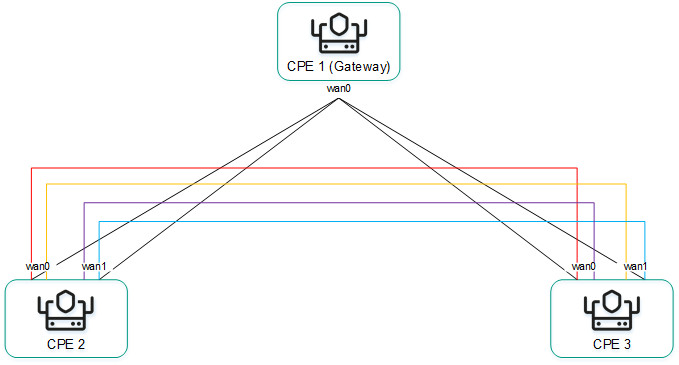
To build a Partial-Mesh topology, you need to assign the SD-WAN gateway and standard CPE device roles to the CPE devices and assign the same topology tag to the standard CPE devices. In this case, SD-WAN gateways establish links with other SD-WAN gateways and with standard CPE devices, while the standard CPE devices establish links with SD-WAN gateways and with each other provided the same topology tag is assigned to the standard CPE devices. If you want to divide the standard CPE devices into groups, you need to assign a unique topology tag to all standard CPE devices in each group, and also assign a topology tag to be shared by at least one standard CPE device in each group.
You can use quality of service to limit bandwidth for CPE devices or traffic classes.
Full-Mesh and Partial-Mesh topology examples:
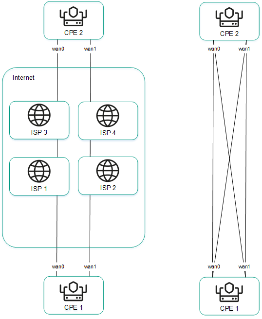
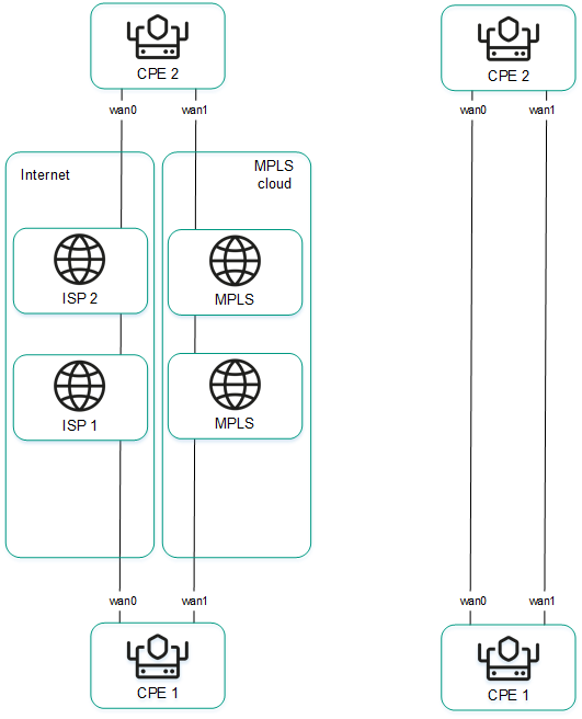
When creating direct links between CPE devices, depending on the type of connectivity of the CPE devices through physical links, the following variants of overlay connectivity are possible:
- All physical links have direct IP connectivity to each other.
- Physical links have partial IP connectivity to each other.


