Managing network services and virtualization of network functions
Network services
Network services relay traffic over the network and apply network functions to it, such as WAN optimization, shaping, and traffic protection. Each network service has a topology that you build using a graphical design tool. You can add components to the topology and connect them to each other.
You can build a topology in a network service template and then assign that network service template to a tenant. Components added to the template topology are automatically assigned to the tenant together with the network service template. A tenant can create and deploy network services, if necessary, using assigned network service templates, and edit network services that are already deployed.
You can use network services to deploy SD-WAN instances. The network service for deploying SD-WAN instances is called the SD-WAN network service (SD-WAN service).
An example of a network service topology is shown in the figure below.

Network service topology
Network function virtualization
Network function virtualization (NFV) lets you use virtualized storage, compute resources, and networks to provide network functions and combine these into network services.
You can deploy virtual network functions (VNF) and physical network functions (PNF) in network services. The difference between virtual and physical network functions is that the orchestrator does not manage the lifecycle of physical network functions. Third-party network functions are supported.
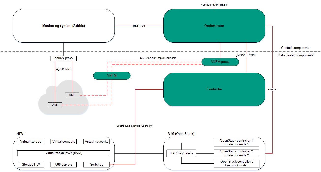
Kaspersky SD-WAN complies with the architecture specified in the ETSI NFV MANO specification (NFV Management and Network Orchestration), which defines the following main functional components:
- Orchestrator.
- Virtual Network Function Managers (VNFM).
- Virtual Infrastructure Manager.
- The Zabbix monitoring system monitors the status of virtual and physical network functions and notifies the orchestrator when a network function needs to be restored or scaled.
- The NFV infrastructure consists of physical resources such as hardware storage, servers, and network devices.
- Controller.
The figure below shows the relations between the solution components and the NFV infrastructure. Components of external solutions are marked in white, Kaspersky SD-WAN components are marked in green, and the red lines are connections between components.
NFV infrastructure