About Full-Mesh and Partial-Mesh topologies
In Full-Mesh and Partial-Mesh topologies, links are established between standard CPE devices. Establishing links between standard CPE devices has the following advantages over a Hub-and-Spoke topology in which standard CPE devices must communicate with each other through SD-WAN gateways:
- Improved aspects of link quality, such as delay, packet loss, and jitter.
- Higher bandwidth of links.
- Economy of hardware resources of SD-WAN gateways.
To build a Full-Mesh topology, you need to assign the standard CPE device role to the CPE devices and assign the same topology tag to the standard CPE devices. In this case, standard CPE devices with the same topology tags establish links with each other.
To build a Partial-Mesh topology, you need to assign the SD-WAN gateway and standard CPE device roles to the CPE devices and assign the same topology tag to the standard CPE devices. In this case, SD-WAN gateways establish links with other SD-WAN gateways and with standard CPE devices, while the standard CPE devices establish links with SD-WAN gateways and with each other provided the same topology tag is assigned to the standard CPE devices. If you want to divide the standard CPE devices into groups, you need to assign a unique topology tag to all standard CPE devices in each group, and also assign a topology tag to be shared by at least one standard CPE device in each group.
You can use quality of service to limit bandwidth for CPE devices or traffic classes.
Full-Mesh and Partial-Mesh topology examples:
- Full-Mesh topology.
The figure below shows a Full-Mesh topology in which all CPE devices establish links with each other. Traffic between CPE 1 and CPE 2 devices is forwarded directly. With a large number of CPE devices and links, this topology can be extremely taxing on the resources of the controller.
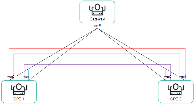
Full-Mesh topology
- Partial-Mesh topology.
The figure below shows a Partial-Mesh topology. This topology is used when direct links between some CPE devices may be undesirable for administrative reasons, or impossible for technical reasons. In this topology, you can group CPE devices in such a way that CPE devices in the same group communicate directly with each other and communicate with CPE devices from other groups through a transit CPE device.
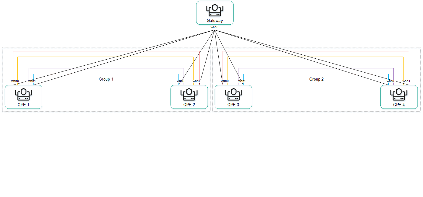
Partial-Mesh topology
A CPE device can belong to multiple groups at the same time, as shown in the figure below.
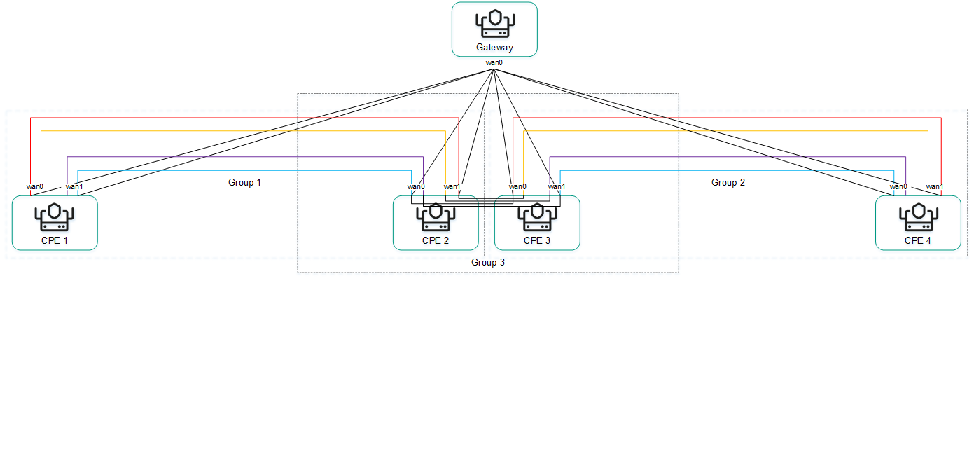
Partial-Mesh topology, CPE devices in multiple groups
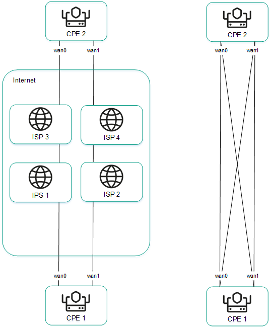
When creating direct links between CPE devices, depending on the type of connectivity of the CPE devices through physical links, the following variants of overlay connectivity are possible:
- All physical links have direct IP connectivity to each other.
Thanks to the connectivity within the internet, CPE devices can establish the maximum number of links with each other (see the figure below).
Full physical connectivity between CPE devices
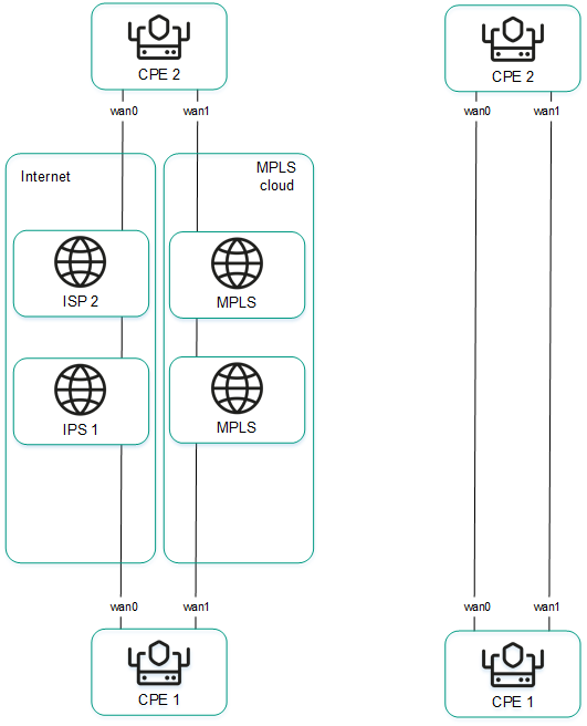
- Physical links have partial IP connectivity to each other.
In the figure below, the internet cloud and the MPLS cloud are not connected to each other, so links can only be established through SD-WAN interfaces of the WAN type that belong to the same cloud. CPE1:WAN0 → CPE2:WAN1 and CPE1:WAN1 → CPE2:WAN0 links cannot be established.
Other overlay network connectivity scenarios are also possible if IP connectivity between SD-WAN interfaces of the WAN type of CPE devices within the same cloud is impossible for other reasons, for example, when using an MPLS topology that does not support direct communication between CPE devices, or due to the presence of NAT/PAT or ACL on the internet.