Kaspersky SD-WAN
- Kaspersky SD-WAN Help
- About Kaspersky SD-WAN
- Architecture of the solution
- Deploying Kaspersky SD-WAN
- Redundancy of solution components
- About the installation archive
- About the attended, unattended, and partially attended action modes
- Preparing the administrator device
- Managing passwords
- Preparing the configuration file
- Replacing the graphics of the orchestrator web interface
- Replacement of a failed controller node
- Upgrading Kaspersky SD-WAN
- Removing Kaspersky SD-WAN
- Logging in and out of the orchestrator web interface
- Licensing of Kaspersky SD-WAN
- User interface of the solution
- Navigating to the orchestrator API
- Managing the Kaspersky SD-WAN infrastructure
- Managing domains
- Managing data centers
- Managing management subnets
- Managing controllers
- Managing a VIM
- Managing users and their access permissions
- Multitenancy
- Managing CPE devices
- About the interaction of the CPE device and the orchestrator
- About the interaction of the CPE device and the controller
- Default credentials of KESR CPE devices
- Scenario: Automatic registration (ZTP) of a CPE device
- Scenario: Deployment on the VMware virtualization platform and automatic registration (ZTP) of a vCPE device
- Scenario: Re-registering a CPE device
- Managing CPE templates
- Managing CPE devices
- Adding a CPE device
- Generating an URL with basic CPE device settings
- Manually registering a CPE device
- Unregistering a CPE device
- Specifying the address of a CPE device
- Enabling and disabling a CPE device
- Restarting a CPE device
- Shutting down a CPE device
- Connecting to the CPE device console
- Viewing the password of a CPE device
- Exporting orchestrator and controller connection settings and SD-WAN interfaces from a CPE device
- Exporting network interfaces from a CPE device
- Changing the DPID of a CPE device
- Deleting CPE devices
- Two-factor authentication of a CPE device
- Managing certificates
- Automatically deleting and disabling CPE devices
- Grouping CPE devices using tags
- Configuring logs on CPE devices
- Specifying NTP servers on CPE devices
- Managing modems
- Updating firmware
- Manually updating firmware on a CPE device
- Uploading firmware to the orchestrator web interface
- Scheduling firmware updates on selected CPE devices
- Scheduling firmware updates on CPE devices with specific tags
- Restoring firmware of a KESR-M1 CPE device
- Restoring firmware of a KESR-M2-5 CPE device
- Correspondence of CPE device models with firmware versions
- Deleting firmware
- Additional configuration of CPE devices using scripts
- Managing network interfaces
- Creating network interfaces
- Creating a network interface with automatic assignment of an IP address via DHCP
- Creating a network interface with a static IPv4 address
- Creating a network interface with a static IPv6 address
- Creating a network interface for connecting to an LTE network
- Creating a network interface for connecting to a PPPoE server
- Creating a network interface without an IP address
- Editing a network interface
- Disabling or enabling a network interface
- Canceling the application of network interface settings to a CPE device
- Deleting a network interface
- Creating network interfaces
- Configuring the connection of a CPE device to the orchestrator and controller
- Managing SD-WAN interfaces
- About sending information about SD-WAN interfaces of the WAN type to the controller
- Package fragmentation
- Traffic queues on SD-WAN interfaces
- Creating an SD-WAN interface of the WAN type
- Editing an SD-WAN interface
- Disabling or enabling an SD-WAN interface
- Deleting an SD-WAN interface of the WAN type
- Managing service interfaces
- Managing OpenFlow port groups
- Configuring a UNI for connecting CPE devices to network services
- Adding a static route
- Filtering routes and traffic packets
- Route exchange over BGP
- Route exchange over OSPF
- Using BFD to detect routing failures
- Ensuring high availability with VRRP
- Transmission of multicast traffic using PIM and IGMP protocols
- Managing virtual routing and forwarding (VRF) tables
- Monitoring traffic packet information using the NetFlow protocol
- Diagnosing a CPE device
- Running scheduled tasks on CPE devices
- IP address and subnet ranges for CPE devices
- Managing the firewall
- Managing network services and virtualization of network functions
- Managing network service templates
- Managing network services
- Scenario: Deploying a virtual network function
- Scenario: Deploying a physical network function
- Managing VNF and PNF packages
- Specifying a brief description of a shared network service
- Managing virtual network functions
- Selecting the flavour of a virtual network function
- Configuring external connection points of a virtual network function
- Basic settings of a virtual network function
- Hosting the virtual network function in a data center and on a uCPE device
- Stopping or starting a virtual network function or a VDU that is part of it
- Pausing or unpausing a virtual network function or a VDU that is part of it
- Suspending or unsuspending a virtual network function or a VDU that is part of it
- Soft rebooting a virtual network function or a VDU that is part of it
- Hard rebooting of a virtual network function or a VDU that is part of it
- Redeploying a virtual network function or a VDU that is part of it
- Auto-healing a virtual network function or a VDU that is part of it
- Managing VDU snapshots
- Managing physical network functions
- Configuring a P2P service
- Configuring a P2M service
- Configuring an M2M service
- Configuring a shared network (OS 2 SHARED)
- Configuring a virtual router (OS vRouter)
- Configuring a VLAN
- Configuring a VXLAN
- Configuring a flat network
- Configuring a UNI
- Monitoring solution components
- Specifying the Zabbix server
- Specifying the Zabbix proxy server
- Configuring CPE device monitoring
- Viewing monitoring results
- Viewing problems
- Viewing the status of the solution and its components
- Viewing logs
- Viewing and deleting service requests
- Sending CPE device notifications to users
- Selecting the Docker container log verbosity
- Monitoring CPE, VNF, and PNF devices using SNMP
- Link monitoring
- Building an SD-WAN network between CPE devices
- Quality of Service (QoS)
- Transmission of traffic between CPE devices and client devices using transport services
- Traffic packet duplication
- Scenario: Directing application traffic to a transport service
- Managing Point-to-Point (P2P) transport services
- Managing Point-to-Multipoint (P2M) transport services
- Managing Multipoint-to-Multipoint (M2M) transport services
- Managing L3 VPN transport services
- Managing IP multicast transport services
- Managing transport services in an SD-WAN instance template
- Managing transport services in a CPE template
- Traffic mirroring and forwarding between CPE devices
- Appendices
- Glossary
- Control plane
- Controller
- Customer Premise Equipment (CPE)
- Data plane
- Orchestrator
- Physical Network Function (PNF)
- PNF package
- Port security
- SD-WAN Gateway
- SD-WAN instance
- Software-Defined Networking (SDN)
- Software-Defined Wide Area Network (SD-WAN)
- Tenant
- Transport strategy
- Universal CPE (uCPE)
- Virtual Deployment Unit (VDU)
- Virtual Infrastructure Manager (VIM)
- Virtual Network Function Manager (VNFM)
- VNF Package
- Contacting Technical Support
- Information about third-party code
- Trademark notices
About Full-Mesh and Partial-Mesh topologies
In Full-Mesh and Partial-Mesh topologies, links are established between standard CPE devices. Establishing links between standard CPE devices has the following advantages over a Hub-and-Spoke topology in which standard CPE devices must communicate with each other through SD-WAN gateways:
- Improved aspects of link quality, such as delay, packet loss, and jitter.
- Higher bandwidth of links.
- Economy of hardware resources of SD-WAN gateways.
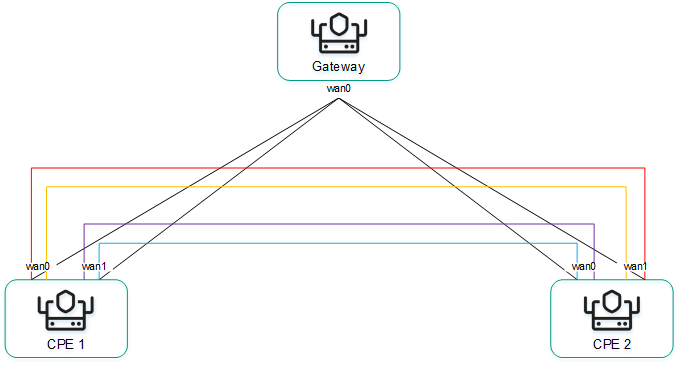
To build a Full-Mesh topology, you need to assign the standard CPE device role to the CPE devices and assign the same topology tag to the standard CPE devices. In this case, standard CPE devices with the same topology tags establish links with each other.
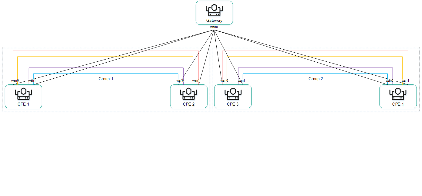
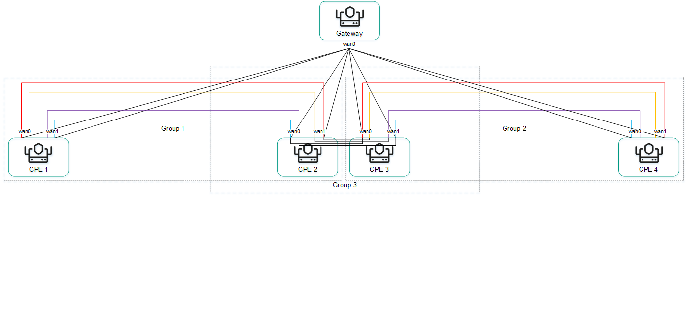
To build a Partial-Mesh topology, you need to assign the SD-WAN gateway and standard CPE device roles to the CPE devices and assign the same topology tag to the standard CPE devices. In this case, SD-WAN gateways establish links with other SD-WAN gateways and with standard CPE devices, while the standard CPE devices establish links with SD-WAN gateways and with each other provided the same topology tag is assigned to the standard CPE devices. If you want to divide the standard CPE devices into groups, you need to assign a unique topology tag to all standard CPE devices in each group, and also assign a topology tag to be shared by at least one standard CPE device in each group.
You can use quality of service to limit bandwidth for CPE devices or traffic classes.
Full-Mesh and Partial-Mesh topology examples:
- Full-Mesh topology.
The figure below shows a Full-Mesh topology in which all CPE devices establish links with each other. Traffic between CPE 1 and CPE 2 devices is forwarded directly. With a large number of CPE devices and links, this topology can be extremely taxing on the resources of the controller.
Full-Mesh topology
- Partial-Mesh topology.
The figure below shows a Partial-Mesh topology. This topology is used when direct links between some CPE devices may be undesirable for administrative reasons, or impossible for technical reasons. In this topology, you can group CPE devices in such a way that CPE devices in the same group communicate directly with each other and communicate with CPE devices from other groups through a transit CPE device.
Partial-Mesh topology
A CPE device can belong to multiple groups at the same time, as shown in the figure below.
Partial-Mesh topology, CPE devices in multiple groups
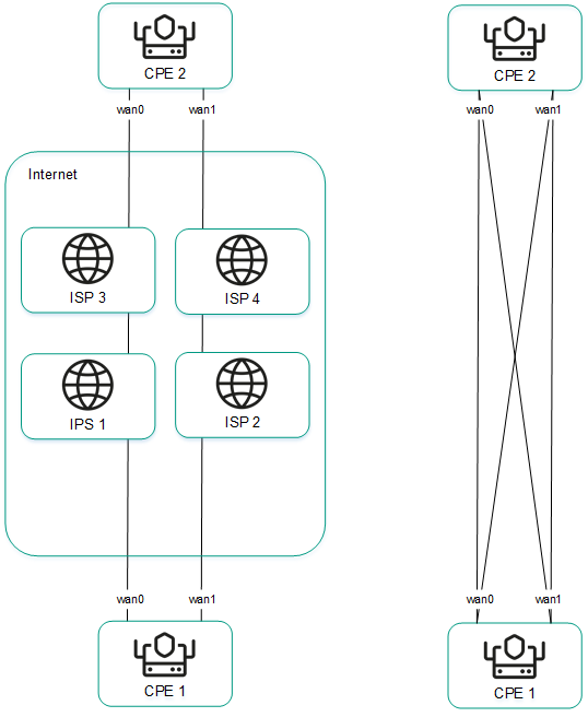
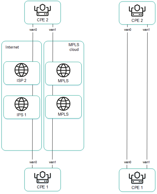
When creating direct links between CPE devices, depending on the type of connectivity of the CPE devices through physical links, the following variants of overlay connectivity are possible:
- All physical links have direct IP connectivity to each other.
Thanks to the connectivity within the internet, CPE devices can establish the maximum number of links with each other (see the figure below).
Full physical connectivity between CPE devices
- Physical links have partial IP connectivity to each other.
In the figure below, the internet cloud and the MPLS cloud are not connected to each other, so links can only be established through SD-WAN interfaces of the WAN type that belong to the same cloud. CPE1:WAN0 → CPE2:WAN1 and CPE1:WAN1 → CPE2:WAN0 links cannot be established.
Other overlay network connectivity scenarios are also possible if IP connectivity between SD-WAN interfaces of the WAN type of CPE devices within the same cloud is impossible for other reasons, for example, when using an MPLS topology that does not support direct communication between CPE devices, or due to the presence of NAT/PAT or ACL on the internet.