Creating a network service template
To create a network service template:
- In the menu, go to the Catalog section.
The network service management page is displayed.
- In the upper part of the page, click + Template.
The graphical design tool for building the topology is displayed.
- Add components to the topology:
- Drag components from the Catalog pane into the graphical design tool. This pane displays the following components:
- Network service templates — when you add a network service template to a topology, the topology is constructed in accordance with the template.
- Shared network services — you must add a shared network service to the topology of network services that you want to connect to the shared network service. You can specify a brief description of the shared network service in the topology.
- Virtual and physical network functions. The actions that you can perform on virtual and physical network functions in the topology are described in the Managing virtual network functions in the topology and Managing physical network functions in the topology sections.
- Drag and drop connections from the Links tab into the graphical design tool. The following connections are displayed on this tab:
- P2P is the Point-to-Point transport service (P2P service). You can configure a P2P service in the topology.
- P2M is the Point-to-Multipoint transport service (P2M service). You can configure a P2M service in the topology.
- M2M is a Multipoint-to-Multipoint transport service (M2M service). You can configure a M2M service in the topology.
The remaining links are relevant to network communication at the VIM level and are established between VNFs hosted by the OpenStack cloud platform:
- OS shared is the shared network through which the shared network service connects to network services. You can configure a shared network in the topology.
- OS vRouter is the virtual L3 router. You can configure a virtual router in the topology.
- OS VLAN is the VLAN for transmitting tagged L2 traffic of the 802.1Q standard You can configure a VLAN in the topology.
- OS VXLAN is a VXLAN for tunneling. You can configure a VXLAN in the topology.
- OS flat is the flat network for transmitting untagged L2 traffic You can configure a flat network in the topology.
- Select the UNI tab and drag CPE device UNIs to the graphical design tool. The tab displays two components, UNI and WAN. Both components designate abstract UNIs that the tenant must replace with real UNIs when creating or editing a network service. The WAN component refers to UNIs that must be connected to the WAN.
You can configure a UNI in the topology.
The components are added to the topology and displayed in the graphical design tool.
- Drag components from the Catalog pane into the graphical design tool. This pane displays the following components:
- Connect the components added to the topology to each other:
- Click the link to which you want to connect a component.
- Click Add leaf to connect a component with the leaf role to the link. If you clicked a P2M service, you can click Add root to connect a component with the root role to the link.
- Click the component that you want to connect to the link. If you clicked a network function or shared network service, select the port to connect to in the displayed window.
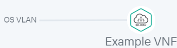
The component is connected to the link, and a line is displayed between them in the topology. For example, the figure below shows the VLAN to which a virtual network function is connected.
- If you want to assign backup UNIs:
A backup UNI can be assigned only for UNIs which are connected to at least one link.
- Click the UNI for which you want to assign a backup UNI.
- Click Reserve.
- Click the UNI that you want to use as the backup.
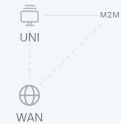
The UNI is designated as the backup UNI, and a dotted line is displayed between the UNI, the backup UNI, and the connection to which the UNI is connected. For example, in the figure below, the WAN UNI is the backup interface for the UNI.
- To delete a component from the topology:
- Click the component that you want to remove from the topology.
- Click Delete.
The component is removed from the topology and is no longer displayed in the graphical design tool.
- If you want to horizontally align the topology, click Arrange.
- If you do not want to hide the descriptions of the added components in the topology, clear the Description check box. This check box is selected by default.
- In the Name field, enter the name of the network service.
- In the upper part of the graphical design tool, click Save.
The network service template is created and displayed in the Catalog pane, on the Templates tab.
