Redundancy of communication channels between CPE devices
Kaspersky SD-WAN guards against interruptions in communication between CPE devices by simultaneously using all available communication channels, for example, Internet or LTE channels.
Active/Active mode
In this mode, all WAN interfaces of CPE devices are in the active state and transmit user traffic.
The SD-WAN Controller balances traffic using 2 to 16 transport paths (multipathing). Balancing evenly distributes traffic among links, which prevents congestion of individual links and performance problems for users. Three balancing modes are supported:
- Per flow balancing, taking into account information at levels L2 to L4. In this mode, two types of balancing are available:
- Equal balancing — the streams are allocated evenly among paths.
- Unequal balancing — the streams are allocated among paths proportionally to the costs of the links.
- Per packet — packets are allocated in proportion to the cost of the links during transmission.
- Broadcast — packets are sent to all links simultaneously to prevent losses.
In Active/Active mode, the CPE device remains available as long as at least one communication channel is operational.
Active/Standby mode
In this mode, you must select the primary and reserve transport paths for the traffic. In this case, balancing is not used. Rules for using the reserve WAN interface in a situation when the path through the main WAN interface becomes unavailable are loaded to the CPE device in advance. In this case, if the main transport path is disrupted, packet switching rules are not rewritten, and the device sends the packets through the reserve interface.
You can configure redundancy at the transport service level. When creating the transport service, you specify reserve service interfaces (reserve SI) on the selected CPE device or on another device. We recommend creating the primary and reserve service interfaces on different devices. Traffic is switched to the reserve service interface if the primary SI is unavailable.
The solution supports creating reserve service interfaces for all types of L2 transport services.
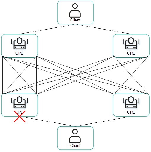
The figures below show typical examples of communication interruptions between CPE devices:
- Failure of one of the CPE devices.
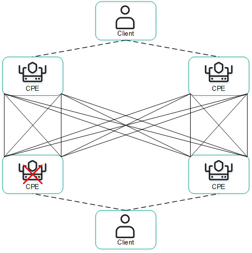
- Failure of a WAN interface of one of the CPE devices.
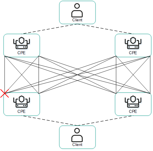
- Loss of connectivity between two CPE devices.
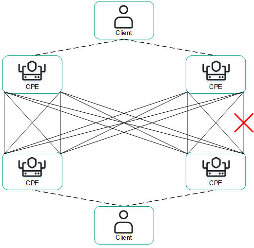
- Failure of a LAN interface of one of the CPE devices.