Creating a network service template
Before creating a template, you must upload all necessary VNF or PNF packages to the orchestrator.
To create a network service template:
- In the menu, go to the Catalog section.
The network service management page is displayed.
- In the upper part of the page, click + Template.
The graphical design tool for building the network service topology is displayed.
- Drag the following network components from the Catalog pane to the graphical design tool to add them to the topology:
- Virtual network functions.
- Physical network functions.
- Shared network services. If a shared network service is added to a topology of multiple network services, it can be used to interconnect those network services.
- Network service template. If, when creating a network service template, you place another template in the topology, the topology is constructed in accordance with that template, and you can then edit the topology by adding or removing components.
To remove an added network component, click it and select Delete from the drop-down list.
- Drag the following links from the Links tab in the lower part of the screen to the graphical design tool to add the links to the topology:
- P2P — P2P transport service
- P2M — P2M transport service
- M2M — M2M transport service
The remaining links are relevant to network communication at the VIM level and are established between VNFs hosted by the OpenStack cloud platform:
- OS shared — a network that can be shared by multiple tenants
- OS vRouter — a router that provides L3 routing
- OS VLAN — a network for transmitting tagged L2 traffic of the 802.1Q standard
- OS VXLAN — a network that provides VXLAN tunneling
- OS flat — a network for transmitting untagged L2 traffic
To remove an added link click it and select Delete from the drop-down list.
- In the lower part of the page, select the UNI tab and drag UNI and/or WAN interfaces to the graphical design tool to add them to the topology. To remove an added interface, click it and select Delete from the drop-down list.
- Configure topology components.
- Connect the links to the network components:
- Click a link and in the drop-down list, select Add leaf to connect a network component that has the Leaf role. If you clicked a P2M service, you can select Add root in the drop-down list to connect a network component that has the Root role.
- Click the network component icon and in the displayed window, select an interface for the connection.
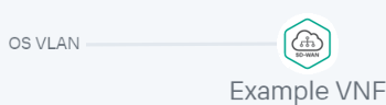
The link is connected to the network component, which is indicated in the topology by a line between them. For example, the figure below shows a VLAN connected to a VNF.
- Connect the links to interfaces:
- Click a link and in the drop-down list, select Add leaf to connect an interface that has the Leaf role. If you clicked a P2M service, you can select Add root in the drop-down list to connect an interface that has the Root role.
- Click the intefrace icon.
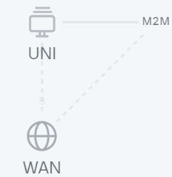
The link is connected to the interface, which is indicated in the topology by a line between them. For example, the figure below shows a P2P service connected to a UNI and WAN interface.

- If necessary, assign backup interfaces to the UNI:
- Click the UNI and in the drop-down list, select Reserve.
A backup interface can be assigned only for UNIs to which at least one link is connected.
- Click the icon of the interface that you want to use as a reserve interface.
The interface is designated as the backup interface for the UNI, and a dotted line is displayed between the UNI, the backup interface, and the link connected to the UNI. For example, in the figure below, the WAN interface is the backup interface for the UNI.
- Click the UNI and in the drop-down list, select Reserve.
- If necessary, do the following:
- Select the Description check box to display a description under each topology component. This check box is selected by default.
- ClickArrange to align topology components vertically.
- In the Name field, enter the name of the network service.
- In the upper part of the page, click Save.
The network service template is created and displayed in the Catalog panel, on the Templates tab.
