About Full-Mesh and Partial-Mesh topologies
Kaspersky SD-WAN supports Full-Mesh and Partial-Mesh topologies. To implement these topologies, the network administrator must grant permission to dynamically create direct links between CPE devices.
Creating direct links between CPE devices improves the performance of Kaspersky SD-WAN thanks to the following:
- Improved qualitative characteristics of the physical communication channel between CPE devices, such as delay, loss, and jitter, compared to the CPE1 → gateway → CPE2 transit scenario of the Hub-and-Spoke topology.
- Greater bandwidth of the direct physical communication channel between CPE devices than in the CPE1 → gateway → CPE2 transit scenario.
- Conservation of the bandwidth of the physical communication channel and of hardware resources of the gateway when using direct links.
An example of the Full-Mesh topology is shown in the figure below. In this topology, all CPE devices create direct links among themselves, using all available physical communication channels. This allows routing traffic between CPE1 and CPE2 directly. However, with a large number of CPEs and links, this topology can be extremely taxing on the resources of the SD-WAN Controller.
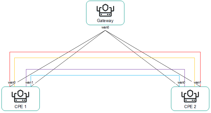
Full-Mesh topology
An example of the Partial-Mesh topology is shown in the figure below. This topology is used when direct links between some CPE devices may be undesirable, for example, for administrative reasons, or impossible for technical reasons. In this topology, the network administrator can group devices in such a way that devices in the same group communicate directly with each other, while communication with devices from other groups happens through a transit device.
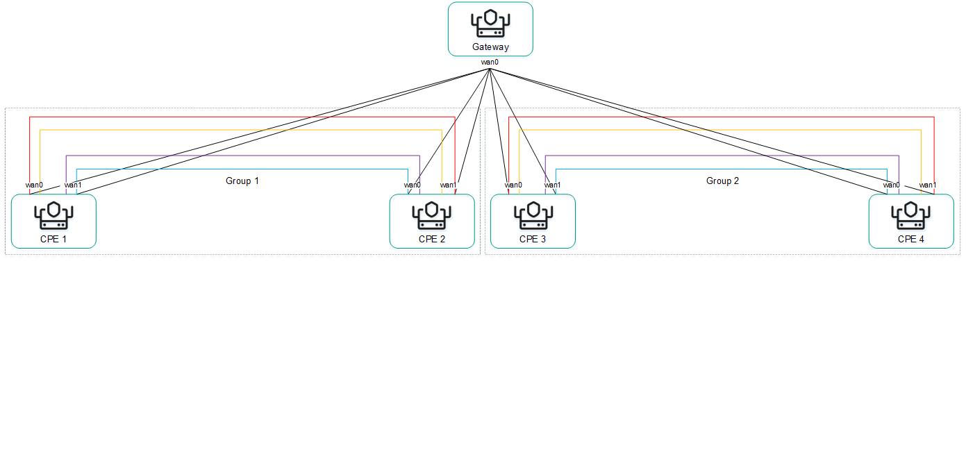
Partial-Mesh topology
A CPE device can belong to multiple groups at the same time, as shown in the figure below.
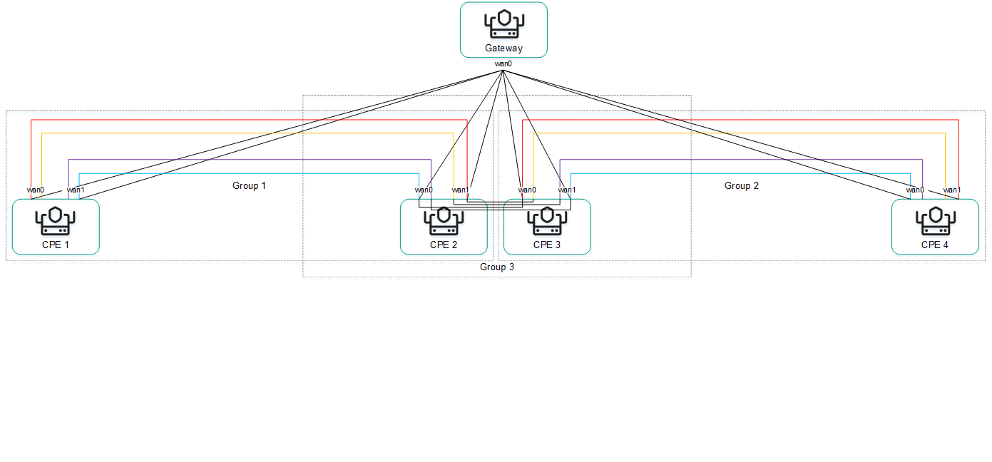
Partial-Mesh topology, CPE devices in multiple groups
When creating direct links between CPE devices, depending on the type of connectivity of the devices through physical channels, the following variants of overlay connectivity are possible:
- All physical communication channels have direct IP connectivity to each other (see the figure below). Thanks to the connectivity within the internet, CPE devices can establish the maximum number of direct links among themselves.
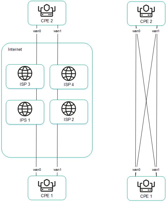
Full physical connectivity between CPE devices
- Physical communication channels have partial connectivity (see the figure below). In the example shown in the figure below, the internet cloud and the MPLS cloud are not interconnected, so links can only be established through WAN interfaces belonging to the same cloud. CPE1:WAN0 → CPE2:WAN1 and CPE1:WAN1 → CPE2:WAN0 links cannot be created.
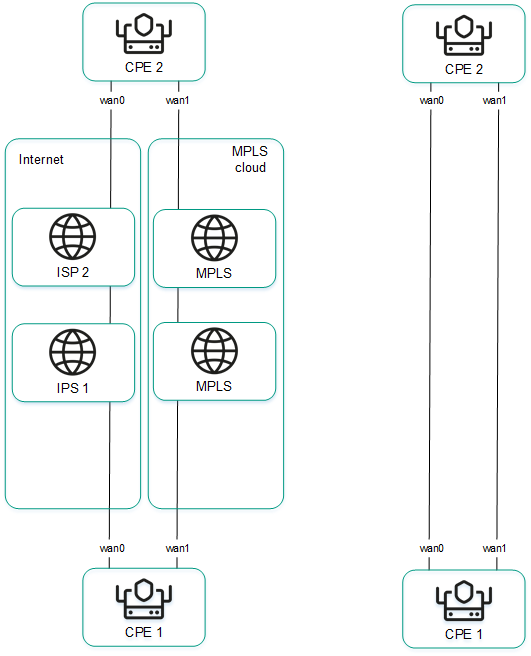
Partial physical connectivity between CPE devices
Other overlay network connectivity scenarios are also possible if IP connectivity between WAN interfaces of CPE devices within the same cloud is impossible for other reasons, for example, when using an MPLS topology that does not support direct communication between devices, or due to the presence of NAT/PAT or ACL on the internet.
