Contents
- About Kaspersky SD-WAN
- Architecture of the solution
- Redundancy and fault tolerance
- Ensuring security
- User interface of the solution
- Authentication in Kaspersky SD-WAN
- Setting and resetting the default page
- Switching between light and dark theme
- Limiting the duration of a user session when idle
- Viewing active user sessions
- Configuring the Docker container log verbosity
- Navigating to the orchestrator API
- Changing the language of the orchestrator web interface
- Licensing of Kaspersky SD-WAN
- Managing Kaspersky SD-WAN domains
- Managing data centers
- Managing VIMs
- Managing subnets
- Viewing logs
- Service Requests
- Managing network services
- User roles and actions with network services
- Uploading a VNF or PNF package to the orchestrator
- Network service template
- Creating a network service
- Configuring network service topology components
- Editing a network service topology
- Deploying a network service
- Checking the consistency of a network service
- Redeploying a network service and its components
- Auto-Healing
- Managing VNFs and VDUs in a network service
- Viewing the network service log
- Deleting a network service
- Managing confirmation requests
- Managing users
- Creating an LDAP connection
- Editing an LDAP connection
- Changing the password of an LDAP connection
- Deleting an LDAP connection
- Creating access permissions
- Editing access permissions
- Cloning access permissions
- Removing an access permission
- Creating a user
- Editing a user
- Changing user password
- Activating or blocking a user
- Deleting a user
- Creating a user group
- Editing a user group
- Deleting a user group
- Managing tenants
- Creating a tenant
- Assigning a VIM to a tenant
- Assigning topology components to a tenant
- Assigning compute resources to a tenant
- Assigning a user to a tenant
- Assigning a user group to a tenant
- Authenticating as an administrator in the tenant's orchestrator web interface
- Editing a tenant
- Deleting a tenant
- Managing SD-WAN instances
- Creating an SD-WAN instance template
- Setting the default SD-WAN instance template
- Deleting an SD-WAN instance template
- Adding a tenant to an SD-WAN instance template
- Removing a tenant from an SD-WAN instance template
- Configuring high availability
- Choosing a transport strategy
- Adding a tenant to an SD-WAN instance
- Removing a tenant from an SD-WAN instance
- Viewing devices assigned to an SD-WAN Instance
- Deleting an SD-WAN instance
- Creating a pool of SD-WAN instances
- Adding an SD-WAN instance to a pool
- Removing an SD-WAN instance from a pool
- Deleting a pool of SD-WAN instances
- Managing CPE devices
- Composition of CPE devices
- Composition of uCPE devices
- SD-WAN managementTunnel management transport service
- Automatic configuration of CPE (ZTP) devices
- CPE device statuses and states
- Ensuring connectivity of CPE devices with SD-WAN Controllers
- Automatically updating the link cost based on maximum speed of the interface
- CPE template
- Creating a CPE device
- Specifying the address of a CPE device
- Registering a CPE device
- Activating or deactivating a CPE device
- Using a web address to activate a CPE device
- Connecting to the CPE device console
- Deleting a CPE device
- Viewing the password of a CPE device
- Restarting a CPE device
- Shutting down a CPE device
- Exporting settings and SD-WAN interfaces from a CPE device
- Exporting network interfaces from a CPE device
- Searching for CPE devices
- Automatic removal and deactivation of a CPE device
- Two-factor authentication of a CPE device
- Orchestrator certificates
- Tags
- Out-of-band management of CPE devices
- Managing CPE devices in SD-WAN controller menu
- Viewing the OpenFlow table of a CPE device
- Viewing statistics of OpenFlow interfaces
- Viewing statistics of queues on LAN interfaces
- Navigating to service interfaces on a CPE device
- Viewing the specifications of a CPE device
- Viewing the usage of a CPE device
- Changing the status of a CPE device in the SD-WAN Controller
- Changing the MAC address of a CPE device
- Terminating the TCP session between a CPE device and the SD-WAN Controller
- Scripts
- Network interfaces
- Configuring the connection of a CPE device to the SD-WAN network
- SD-WAN interfaces
- OpenFlow interfaces
- Service interfaces and UNIs
- Creating a service interface
- Creating an ACL interface
- Viewing the usage of a service interface and an ACL interface
- Deleting a service interface and an ACL interface
- Creating a UNI template
- Creating a UNI in a template
- Editing a UNI in a template
- Deleting a UNI in a template
- Deleting a UNI template
- Creating a UNI
- Editing a UNI
- Deleting a UNI
- Filtering routes
- The BGP dynamic routing protocol
- The OSPF dynamic routing protocol
- The BFD protocol
- Creating or deleting a static IPv4 route
- The VRRP protocol
- Viewing the settings of the CPE device connection to the service provider network
- Configuring the connection of a CPE device to a Syslog server
- Configuring the connection of a CPE device to an NTP server
- Firmware
- Monitoring solution components
- Tunnels, segments, and paths
- Configuring topology
- Quality of Service (QoS)
- Transport services
- Point-to-Point (P2P) transport service
- Point-to-Multipoint (P2M) transport service
- Multipoint-to-Multipoint (M2M) transport service
- Adding a transport service in a CPE template
- Editing a transport service in a CPE template
- Deleting a transport service from a CPE template
- Scenario: Directing application traffic to a transport service
- Traffic mirroring
- Task scheduler
- Configuring the SD-WAN Controller
- Editing the SD-WAN Controller
- Restarting the SD-WAN Controller
- Downloading a backup SD-WAN Controller configuration file
- Restoring the SD-WAN Controller
- Deleting the SD-WAN Controller
- SD-WAN Controller properties
- Viewing information about SD-WAN Controller nodes
- Viewing the topology of a deployed SD-WAN instance
- Contacting Technical Support
- Appendices
- Glossary
- Control plane
- Customer Premise Equipment (CPE)
- Data plane
- DSCP values
- Graceful restart
- Orchestrator
- Physical Network Function (PNF)
- PNF package
- SD-WAN Controller
- SD-WAN Gateway
- Software-Defined Networking (SDN)
- Software-Defined Wide Area Network (SD-WAN)
- Tenant
- Universal CPE (uCPE)
- Virtual Infrastructure Manager (VIM)
- Virtual Network Function (VNF)
- Virtual Network Function Manager (VNFM)
- VNF Package
- Information about third-party code
- Trademark notices
About Kaspersky SD-WAN
Kaspersky SD-WAN is used to build Software-Defined Wide Area Networks (SD-WAN) for routing traffic over communication channels using Software Defined Networking (SDN) technology. The main advantage of such networks is the ability to automatically determine the most efficient routes for the traffic.
The SDN technology implies the separation of the control plane and the data plane. The control plane comprises an
and an . The control plane controls the transmission of traffic packets over the network through devices (hereinafter referred to as CPE devices or CPEs) that are installed at client locations and together form the data plane. Alternatively, the network can be controlled via the API.Network Function Virtualization (NFV) is performed in accordance with the standards set out in the NFV MANO (NFV Management and Network Orchestration) specification of the European Telecommunications Standards Institute (ETSI).
The solution is intended for service providers, as well as organizations with a large branch network, and replaces standard routers in wide area networks. The deployment procedure is independent of particular transport technologies used on your network. The solution also supports sending traffic over multiple links based on application requirements regarding bandwidth and quality of service.
Kaspersky SD-WAN lets you do the following:
- Smart traffic control.
- Automatic configuration of CPE devices. This functionality makes deployment of devices on location less personnel-intensive.
- Centralized management of the network infrastructure through the orchestrator web interface. For example, you can use the orchestrator web interface to configure CPE devices and links.
- Continuous monitoring of the network topology and automatically responding to any changes. For example, you can configure the traffic to be switched to a backup link in case the main link fails.
- Automatic response of the network to changes in the quality of service of communication channels to meet the requirements of various applications used on the network.
The figure below shows a diagram of an SD-WAN network built using the Kaspersky SD-WAN solution.

SD-WAN network diagram
Distribution kit
To learn more about purchasing the solution, please visit the Kaspersky website (https://www.kaspersky.com) or contact partner companies.
The distribution kit includes the following components:
- Docker containers for solution deployment:
- knaas-ctl
- knaas-orc
- knaas-www
- knass-vnfm
- knaas-vnfm-proxy
- Firmware for installing and managing CPE devices.
- A file with the text of the End User License Agreement, which stipulates the terms and conditions that you must accept to use the solution.
- Kaspersky SD-WAN Online Help files that let you read documentation without an internet connection.
The content of the distribution kit may differ depending on the region in which the solution is distributed.
Page top
Hardware and software requirements
The solution includes the following software modules:
- Orchestrator, which is part of the backend of the solution.
- Orchestrator web interface, which is part of the frontend of the solution.
- Orchestrator database (MongoDB version 5.0.7).
- .
- NGINX web server for balancing HTTP and HTTPS requests to VNFMs and providing web proxies to CPE devices and VNFs.
- Redis 6.2.7 resident database.
- SD-WAN Controller.
Modules are deployed as Docker containers for stand-alone installation and scaling. If necessary, you can provision additional resources (CPU cores, RAM) to each module and distribute them among multiple servers to increase the overall performance of the solution.
Kaspersky SD-WAN components can be deployed on multiple physical servers or virtual machines (VMs). KVM and VMware virtualization platforms are supported. You must ensure the availability of servers or virtual machines for installing Kaspersky SD-WAN, an external Zabbix 5.0.26 monitoring system, and an SD-WAN Controller.
The controller can be deployed in two ways:
- As a VNF in the OpenStack cloud platform (Xena release). Controller nodes are hosted on compute nodes.
- As a on separate virtual machines.
Before deploying Kaspersky SD-WAN, make sure that your network infrastructure meets the following hardware and software requirements.
Hardware requirements
Hardware requirements are listed in the following tables. Note that these requirements depend on the number of managed CPE devices used in the SD-WAN instance. The tables provide typical values, so if you need to calculate the exact requirements for your deployment scheme, please contact Kaspersky technical support.
Hardware requirements for servers or virtual machines for orchestrator deployment
CPE devices |
CPU cores |
RAM, GB |
Disk space, GB |
Network adapters |
Virtual machines |
|---|---|---|---|---|---|
up to 50 |
8 |
8 |
105 |
2 |
3 |
up to 100 |
8 |
10 |
110 |
2 |
3 |
up to 250 |
8 |
12 |
125 |
2 |
3 |
up to 500 |
8 |
16 |
150 |
2 |
3 |
up to 1,000 |
10 |
24 |
200 |
2 |
3 |
up to 5,000 |
12 |
32 |
600 |
2 |
3 |
up to 10,000 |
16 |
64 |
1100 |
2 |
5 |
Hardware requirements for servers or virtual machines for deployment of other components of the solution
CPE devices |
CPU cores |
RAM, GB |
Disk space, GB |
Network adapters |
Containers |
|---|---|---|---|---|---|
SD-WAN Controller |
|||||
up to 50 |
4 |
8 |
64 |
2 |
3 |
up to 100 |
6 |
8 |
64 |
2 |
3 |
up to 250 |
8 |
16 |
64 |
2 |
3 |
up to 500 |
8 |
16 |
64 |
2 |
6 |
up to 1,000 |
8 |
16 |
64 |
2 |
12 |
up to 5000 |
8 |
16 |
64 |
2 |
60 |
up to 10,000 |
8 |
16 |
64 |
2 |
120 |
VNFM |
|||||
up to 50 |
4 |
8 |
20 |
2 |
3 |
up to 100 |
4 |
8 |
20 |
2 |
3 |
up to 250 |
4 |
8 |
20 |
2 |
3 |
up to 500 |
4 |
8 |
20 |
2 |
3 |
up to 1000 |
4 |
10 |
20 |
2 |
3 |
up to 5000 |
4 |
12 |
20 |
2 |
3 |
up to 10000 |
4 |
16 |
20 |
2 |
3 |
Zabbix monitoring system |
|||||
up to 50 |
4 |
8 |
100 |
2 |
3 |
up to 100 |
4 |
10 |
200 |
2 |
3 |
up to 250 |
6 |
12 |
350 |
2 |
3 |
up to 500 |
8 |
24 |
600 |
2 |
3 |
up to 1,000 |
10 |
32 |
1100 |
2 |
3 |
up to 5,000 |
12 |
64 |
5100 |
2 |
3 |
up to 10,000 |
16 |
128 |
10100 |
2 |
3 |
If you need to connect more than 250 CPE devices, deploy additional SD-WAN Controller clusters.
For detailed information about the hardware requirements of the Zabbix monitoring system, see the official documentation of the Zabbix solution.
When deploying the solution, an offline map is configured. Consider the following disk space requirements:
- The offline map (central-fed-district-latest.osm.pbf) takes up approximately 100 GB.
- Geocoding data takes up approximately 10 GB.
We recommend considering the possibility of overcommitment at the resource planning stage for your SD-WAN instance deployment. The maximum overcommitment ratio available when deploying containers is 3. The ratio is determined by the following characteristics of the SD-WAN instance:
- Number of CPE devices in use
- Frequency of network state changes
- Traffic bandwidth
- Size of transmitted traffic packets
Channel requirements
The following channels are supported:
- MPLS transport networks
- Broadband links for connecting to the Internet
- Leased communication lines
- Wireless connections including 3G, 4G, LTE, and 5G
- Satellite communication channels
Software requirements
Docker 1.5 or later is required. The following 64-bit operating systems are supported:
- Ubuntu 20 LTS or later
- Astra Linux 1.7 or later (security level: "Orel").
Supported browsers
You can use the following browsers to manage the orchestrator web interface:
- Google Chrome 100 or later
- Firefox 100 or later
- Microsoft Edge 100 or later
- Opera 90 or later
- Safari 15 or later
CPE device requirements
Kaspersky SD-WAN supports the following devices:
- KESR-M1-R-5G-2L-W
- KESR-M2-K-5G-1L-W
- KESR-M2-K-5G-1S
- KESR-M3-K-4G-4S
- KESR-M4-K-2X-1CPU
- KESR-M4-K-8G-4X-1CPU
- KESR-M5-K-8G-4X-2CPU
- KESR-M5-K-8X-2CPU
Kaspersky experts carried out tests to confirm the functionality of CPE devices when providing the L3 VPN service (see the table below). DPI (Deep Packet Inspection) was not used on the tested devices, and traffic encryption was disabled.
Tested CPE device models (L3 VPN Service)
Model |
Packet size, bytes |
Bandwidth (Mbps) |
|---|---|---|
KESR-M1
|
IMIX (417) |
30 |
Large (1300) |
115 |
|
KESR-M2
|
IMIX (417) |
165 |
Large (1300) |
241 |
|
KESR-M3
|
IMIX (417) |
805 |
Large (1300) |
1150 |
|
KESR-M4 |
IMIX (417) |
1430 |
Large (1300) |
2870 |
|
KESR-M5
|
IMIX (417) |
2875 |
Large (1300) |
5750 |
For more details about the specifications of CPE devices that you can use in Kaspersky SD-WAN, see the website of the solution.
Page top
Shared storage requirements
Kaspersky SD-WAN uses shared storage (hereinafter also referred to as storage) to ensure fault tolerance. This storage contains the following directories with data that the orchestrator needs:
- backups — backup copies of VNF and PNF configurations
- firmware — CPE device firmware
- images — VNF images
- vnf_configs — files that can be used by scripts when configuring VNFs
- vnf_descriptions — VNF descriptors
We recommend using your own shared storage. The requirements for deploying the shared storage are as follows:
- Support for simultaneous read and write from multiple hosts.
- The recommended size depends on the size of the files being stored, but at least 40 GB of available protected space that supports further expansion.
- Bandwidth of the communication channel between the storage and the orchestrator must be at least 1 Gbps; 10-Gigabit Ethernet or 8-Gigabit FC (Fiber Channel) is recommended.
- The supported IOPS (input/output operations per second) value must be at least 250, at least 400 IOPS is recommended.
- Storage type:
- NFS
- iSCSI
- FC
- CephFS
- The storage must be mounted.
- Must stay available if the host restarts.
What's new
Kaspersky SD-WAN 2.1 has the following new and improved functionality:
- The OSPF dynamic routing protocol is supported.
- Additional connection scenarios are now supported for connections between CPE devices when the SD-WAN gateway is behind NAT.
- Additional scenarios are now supported for CPE devices that use Internet and MPLS channels at the same time.
- Configuring of Controller IP addresses on WAN interfaces of CPE devices is supported.
- Now you can manage the SD-WAN topology map without a network connection.
- Added token and password rotation for CPE devices.
- Monitoring data can now be encrypted when it is sent outside the SD-WAN link.
Architecture of the solution
Kaspersky SD-WAN includes the following components:
- The Orchestrator provides a graphical web interface for managing the infrastructure of the solution, including CPE devices. Note that the orchestrator can manage multiple SD-WAN instances.
- The SD-WAN Controller centrally manages CPE devices via the OpenFlow protocol, as well as the overlay network, on top of which you can create transport services.
- CPE devices form an SDN fabric in the form of an overlay network. CPE devices can be assigned the SD-WAN gateway role. In this case, links are automatically established from all other devices that are assigned the standard CPE role. If you plan to use SD-WAN gateways in the network topology, we recommend installing them in multiple instances for fault tolerance.
- Virtual Network Function Manager (hereinafter also referred to as VNFM) – Manages the configuration of (VNF) and CPE devices.
All components of the solution are deployed in data centers, with the exception of CPE devices, which are installed on remote locations. If you are deploying an SD-WAN instance using VNF, the following additional components may be included in the solution architecture:
- The SDN controller provides management and configuration of hardware and software switches in the data center. This component is optional.
- The VIM provides management of computational, networking, and storage resources. All of these resources are required for VNF to run.
Kaspersky SD-WAN has a distributed microservice architecture that is deployed as Docker containers (see the figure below). An SD-WAN Controller can comprise a single node or a cluster of three/five nodes. Cluster nodes of the controller are separate virtual machines and can run on different physical servers for fault tolerance.

Architecture of Kaspersky SD-WAN
Page top
Redundancy and fault tolerance
Fault tolerance ensures continuous and uninterrupted transmission of traffic over the SD-WAN network and functioning of network services. Fault tolerance is enhanced by the use of redundancy and failover mechanisms at different levels of the network infrastructure, for example, you can create backup service interfaces.
A fault-tolerant network can remain operational in case of minor problems as well as major disasters involving central components such as routers, links, and data centers. When a component fails, a backup component of the same type takes its place. For example, you can create a backup link to which traffic is transferred if the main link becomes unavailable.
Fault tolerance makes it easier to balance the load across multiple links by optimizing the utilization of traffic bandwidth and avoiding congestion. This helps avoid any existing link becoming a bottleneck in the network topology.
Kaspersky SD-WAN maintains continuous operation in the event of the following types of faults:
- Failure of a central component, such as orchestrator, SD-WAN Gateway, or SD-WAN Controller
- Failure or overload of communication channels between geographically redundant central components, when network components are located at geographically dispersed locations to make data storage more reliable
- Failure or congestion of communication channels between CPE devices and SD-WAN gateways
Redundancy of central components of the solution
Kaspersky SD-WAN supports two component deployment schemes: N+1 and 2N+1.
The N+1 deployment scheme means that one backup component is deployed alongside an active component. If the active component fails, the backup component instantly takes its place, ensuring continuity of operation.
The 2N+1 deployment scheme is an expanded version of N+1 and differs in that it has an additional level of redundancy. In this scheme, the active component consists of two sets. These are synchronized with each other, and one can take the place of the other if a malfunction occurs. One extra backup component is also deployed. This redundancy scheme allows components to remain operational even when multiple failures occur in a row.
The table below shows the redundancy schemes and protocols that are used for different components of the solution.
Redundancy schemes for components of the solution
Component |
Redundancy scheme |
Protocol used |
|---|---|---|
Orchestrator |
N+1 |
REST |
Orchestrator web interface |
N+1 |
REST |
Orchestrator database |
2N+1 |
MONGODB |
SD-WAN Controller and its database |
2N+1 |
OPENFLOW (TLS) |
SD-WAN Gateway |
N+1 |
GENEVE |
An example of locating solution components in geographically dispersed data centers is shown in the figure below. All subsequent figures use the same symbols:
- orchestrator — orc
- orchestrator web interface — www
- orchestrator database — orc-dbs
- SD-WAN Controller and its database — ctl
- SD-WAN gateway — GW
For components of the solution that are N+1 redundant, two nodes are deployed in separate data centers. Each of the nodes is in the active state. You can use a virtual IP address or DNS service to select the node to which requests are directed.

Placing solution components in geographically dispersed data centers
Components that are 2N+1 redundant form a cluster. This cluster contains one primary node and two nodes providing redundancy. You can designate one of the nodes as an arbiter to economize resources and reduce the requirements for the links.
If a cluster node is designated as an arbiter, it does not contain a database and you cannot make it the primary node. The arbiter node takes part in voting when the primary node is selected and exchanges periodic service packets (heartbeats) with other nodes.
The figure below shows an example of an failure at one of the locations and how the solution responds to it. This example shows an accident in which the nodes of the solution component cluster fail at location 1.

Accident at location 1
If nodes of the solution component cluster at location 1 fail, the following events occur:
- Node orc-dbs 2 and arbiter node orc-dbs 3 lose contact with node orc-dbs 1, and subsequently vote for a new primary node.
- Arbiter node orc-dbs 3 cannot be the primary node, therefore orc-dbs 2 becomes the primary node and informs the orchestrator of its role.
- Node ctl 2 and arbiter node ctl 3 lose contact with node ctl 1, and subsequently vote for a new primary node.
- Arbiter node ctl 3 cannot be the primary node, therefore ctl 2 becomes the primary node and informs the orchestrator of its role.
The figure below shows an accident in which the nodes of the solution component cluster fail at location 2.

Accident at location 2
If nodes of the solution component cluster at location 2 fail, the following events occur:
- Node orc-dbs 1 and arbiter node orc-dbs 3 lose contact with node orc-dbs-2, after which node orc-dbs 1 remains the primary node.
- Node ctl 1 node and arbiter node ctl 3 lose contact with node ctl 2, after which node ctl 1 remains the primary node.
The figure below shows an example of an accident in which the connection between location 1 and location 2 is severed.

Connection failure between location 1 and location 2
If cluster nodes of solution components at location 1 and location 2 cannot connect to each other, the following events occur:
- Node orc-dbs 1 loses contact with node orc-dbs 2.
- Node orc-dbs 1 node remains the primary node because arbiter node orc-dbs 3 observes both locations operating normally.
- Node ctl 1 loses contact with node ctl 2.
- Node ctl 1 remains the primary node because arbiter node ctl 3 observes both locations operating normally.
The figure below shows an example of an accident in which the connection between location 1 and other locations is severed.

Failure of connections between location 1 and other locations
If cluster nodes of solution components at location 1 cannot connect to other locations, the following events occur:
- Node orc-dbs 1 loses contact with node orc-dbs 2.
- Node orc-dbs 2 becomes the primary node and informs the orchestrator of its role because the arbiter node orc-dbs 3 observes that location 1 is unavailable.
- Node ctl 1 loses contact with node ctl 2.
- Node ctl 2 becomes the primary node and informs the orchestrator of its role because arbiter node ctl 3 observes that location 1 is unavailable.
Redundancy of communication channels between CPE devices
Kaspersky SD-WAN guards against interruptions in communication between CPE devices by simultaneously using all available communication channels, for example, Internet or LTE channels.
Active/Active mode
In this mode, all WAN interfaces of CPE devices are in the active state and transmit user traffic.
The SD-WAN Controller balances traffic using 2 to 16 transport paths (multipathing). Balancing evenly distributes traffic among links, which prevents congestion of individual links and performance problems for users. Three balancing modes are supported:
- Per flow balancing, taking into account information at levels L2 to L4. In this mode, two types of balancing are available:
- Equal balancing — the streams are allocated evenly among paths.
- Unequal balancing — the streams are allocated among paths proportionally to the costs of the links.
- Per packet — packets are allocated in proportion to the cost of the links during transmission.
- Broadcast — packets are sent to all links simultaneously to prevent losses.
In Active/Active mode, the CPE device remains available as long as at least one communication channel is operational.
Active/Standby mode
In this mode, you must select the primary and reserve transport paths for the traffic. In this case, balancing is not used. Rules for using the reserve WAN interface in a situation when the path through the main WAN interface becomes unavailable are loaded to the CPE device in advance. In this case, if the main transport path is disrupted, packet switching rules are not rewritten, and the device sends the packets through the reserve interface.
You can configure redundancy at the transport service level. When creating the transport service, you specify reserve service interfaces (reserve SI) on the selected CPE device or on another device. We recommend creating the primary and reserve service interfaces on different devices. Traffic is switched to the reserve service interface if the primary SI is unavailable.
The solution supports creating reserve service interfaces for all types of L2 transport services.
The figures below show typical examples of communication interruptions between CPE devices:
- Failure of one of the CPE devices.

- Failure of a WAN interface of one of the CPE devices.

- Loss of connectivity between two CPE devices.

- Failure of a LAN interface of one of the CPE devices.

Ensuring security
Security in Kaspersky SD-WAN is ensured in the
, , and orchestration plane. The security level of the solution as a whole is determined by the security level of each of these planes, as well as the security of their interaction. The following processes take place in each plane:- User authentication and authorization
- Use of secure management protocols
- Encryption of control traffic
- Secure connection of CPE devices
Secure management protocols
We recommend using HTTPS when communicating with the SD-WAN network through the orchestrator web interface or API. You can upload your own certificates to the web interface or use automatically generated self-signed certificates. The solution uses several protocols to transmit control traffic to its components (see the table below).
Protocols for transmitting control traffic
Interacting components |
Protocol |
Additional security measures |
|---|---|---|
Orchestrator and SD-WAN controller |
gRPC |
TLS is used for authentication and traffic encryption between the client and server. |
Orchestrator and CPE device |
HTTPS |
Certificate verification and a token are used for authentication and traffic encryption between the orchestrator and the CPE device. |
SD-WAN controller and CPE device |
OpenFlow 1.3.4 |
TLS is used for authentication and traffic encryption between the SD-WAN controller and the CPE device. |
Secure connection of CPE devices
The solution uses the following mechanisms to identify CPE devices during installation and registration:
- Discovery of CPE device by DPID.
- Deferred registration. You can select the state of the CPE device after successful registration: Activated or Deactivated. A deactivated CPE device must be manually activated after making sure it is installed at the location.
- Two-factor authentication — the client receives a key that must be entered on the CPE device to activate it.
During registration, the CPE device verifies the authenticity of the orchestrator certificate and subsequently sends its DPID and token to the orchestrator. The orchestrator checks if the DPID and token against its database and, if the check is successful, provides the device with information necessary for connecting to the network as well as configuration. The device then establishes a connection with the SD-WAN Controller, which in turn programs the behavior of the device for subsequent traffic processing.
If the DPID is missing from the inventory, the CPE device is displayed with the Unknown status and does not connect to the SD-WAN network.
Using VNF
You can add a layer of security with VNFs deployed in the data center and/or on
. For example, traffic can be routed from a CPE device to a VNF, which provides firewall or proxy server functionality. VNFs can perform the following SD-WAN protection functions:- Next-Generation Firewall (NGFW)
- Protection from DDoS (Distributed Denial of Service) attacks
- Intrusion Detection System (IDS) and Intrusion Prevention System (IPS)
- Anti-Virus
- Anti-Spam
- Filtering system for URL and web content
- DLP (Data Loss Prevention) system for preventing confidential information leaks
- Secure Web Proxy
User interface of the solution
Kaspersky SD-WAN can be managed through the orchestrator web interface. You can use the sections that are displayed in the menu (see the figure below) to configure individual components of the solution. When you go to a section, an additional menu with the section contents is displayed.

Kaspersky SD-WAN menu
The menu contains the following sections:
- Dashboard (
 ) — In this section, you can view information about the current state of solution components such as CPE devices, VNFs, and PNFs.
 - Infrastructure (
 ) — In this section, you can manage the network infrastructure, for example, create domains, add data centers and VIMs. In addition, all SD-WAN Controllers available to you are displayed here.
 - Catalog (
 ) — In this section, depending on your role, you can do the following:
- The platform administrator can upload VNF/PNF packages and create network service templates.
- A tenant administrator can create network services.
- SD-WAN (
 ) — In this section, you can manage CPE devices, SD-WAN instances, UNIs, as well as manage firmware and device certificates.
 - Scheduler (
 ) — In this section, you can manage delayed tasks.
 - Log (
 ) — In this section, you can view the logs of various components of the solution. For example, modifications made by users to CPE device configuration are displayed here.
 - Tenants (
 ) — In this section, you can create tenants and provide various solution components to the tenants, such as CPE devices, VIMs, and UNIs. You can also use this section to connect to the orchestrator web interface of the tenant as an administrator.
 - Users (
 ) — In this section, you can create users, user groups, and access permissions, as well as configure domain authentication.
 - Confirmation (
 ) — In this section, you can manage confirmation requests.
When you navigate to one of the sections, the menu is initially collapsed. To expand the menu, hover your mouse cursor over the icon of one of the sections. You can click the expand button ![]() to disable the automatic minimization of the menu.
to disable the automatic minimization of the menu.
Authentication in Kaspersky SD-WAN
To authenticate in Kaspersky SD-WAN:
- In the address bar of your browser, enter the IP address or name of the Kaspersky SD-WAN server.
- This opens the authentication page; on that page, enter your user name and password. The password must contain at least one uppercase A–Z character, lowercase characters, numerals, and special characters. Password length: 8 to 50 characters.
- Click Log in.
After successful authentication, you are taken to the section or subsection that you set as the default page.
Page top
Setting and resetting the default page
The default page is a section or subsection of the orchestrator web interface (including the SD-WAN Controller configuration menu) that is automatically displayed after your authentication.
To set or reset the default page:
- Go to the section or subsection of the orchestrator web interface that you want to set as the default page.
- In the lower part of the menu, click the settings button
 and in the drop-down list, select Set as the default page.
The
Default page is setmessage is displayed in the upper part. - To reset the default page, click the settings button and in the drop-down list, select Reset the default page.
The
Default page is resetmessage is displayed in the upper part. The Dashboard section is now the default page.
Switching between light and dark theme
To switch between light and dark orchestrator web interface themes,
in the lower part of the menu, click the settings button ![]() and in the drop-down list, select one of the following values:
and in the drop-down list, select one of the following values:
- Dark mode
- Light mode
Limiting the duration of a user session when idle
By default, after authenticating in the orchestrator web interface, you can remain idle for 3,600 seconds, after which your user session is terminated. You can manually increase or decrease the maximum allowed idle time.
To specify the length of time after which your user session is terminated due to inactivity:
- In the lower part of the menu, click the settings button and in the drop-down list, select Session expiration time.
- This opens a window; in that window, enter the time in seconds after which you want to have the session terminated in case of inactivity. Range of values: 60 to 86,400. The default setting is
3,600. - Click Save.
Viewing active user sessions
You can view a list of users that have used your account to authenticate in the orchestrator web interface.
To view active user sessions:
- In the lower part of the menu, click the settings button and in the drop-down list, select Active sessions.
A table of active user sessions is displayed.
- If you want to terminate an individual user session, click End session next to that session.
- If you want to terminate multiple user sessions at the same time:
- Select the check boxes next to the sessions.
- In the upper part of the page, click the Actions button and in the drop-down list, select End session.
Configuring the Docker container log verbosity
Kaspersky SD-WAN automatically keeps logs of Docker containers, which are used to deploy and support solution components. You can select the verbosity level of these logs to monitor containers and restore them more quickly if failures occur.
When you open the log, the following buttons for selecting the level of detail are displayed in the upper part of the page, as well as next to each Docker container:
- Click TRACE to log the most complete information, including debug statements, for advanced troubleshooting.
- Click DEBUG to log detailed information, including variable values and function call records, for troubleshooting and understanding the way in which the container operates.
- Click INFO to log general information for understanding the way in which the container operates and looking up important events. This level of detail is selected by default for all containers.
- Click WARN to log errors or events that do not call for immediate intervention from the user, but may compromise the operation of the container.
- Click ERROR to log errors or exceptions that may compromise the operation of the container. Such records often require immediate intervention from the user.
To configure Docker container log verbosity:
- In the lower part of the menu, click the settings button and in the drop-down list, select Log settings.
A table of Docker containers is displayed.
- Select the Docker container log verbosity:
- To configure the verbosity level of all Docker containers, click the corresponding button in the General logging level section.
- To configure the verbosity level of an individual Docker container, click the corresponding button in the Logging level column.
Navigating to the orchestrator API
To navigate to the orchestrator API,
In the lower part of the menu, click the API button ![]() .
.
This opens a list of API commands that can be used to manage the orchestrator.
Page top
Changing the language of the orchestrator web interface
The orchestrator web interface supports English and Russian languages.
To change the language of the orchestrator web interface,
click one of the following buttons in the lower part of the menu:
- EN to switch the language of the orchestrator web interface to English.
- RU to switch the language of the orchestrator web interface to Russian.
Licensing of Kaspersky SD-WAN
This section covers basic concepts of Kaspersky SD-WAN licensing. If you need to scale the solution, you can purchase additional software and hardware licenses.
About the End User License Agreement
The End User License Agreement is a binding agreement between you and AO Kaspersky Lab, stipulating the terms on which you may use the program. The text of the End User License Agreement in supported languages is located in the license <language code>.rtf files included in the Kaspersky SD-WAN distribution kit.
Read through the terms of the End User License Agreement carefully before you start using Kaspersky SD-WAN.
By confirming that you agree with the End User License Agreement, you signify your acceptance of the terms of the End User License Agreement. You can do this in one of the following ways:
- Initialize the
KNAAS_EULA_AGREEDenvironment variable before starting the Kaspersky SD-WAN Docker container:export KNAAS_EULA_AGREED=yesIn this case, when starting the Kaspersky SD-WAN Docker container, pass the KNAAS_EULA_AGREED environment variable using the
-eoption:docker run -e KNAAS_EULA_AGREED [OPTIONS] IMAGE [COMMAND] [ARG...] - Initialize the
KNAAS_EULA_AGREEDenvironment variable directly when starting the Kaspersky SD-WAN Docker container:docker run -e KNAAS_EULA_AGREED=yes [OPTIONS] IMAGE [COMMAND] [ARG...]
If the KNAAS_EULA_AGREED environment variable is not initialized or is initialized with the value no (KNAAS_EULA_AGREED=no), this means that you do not agree with the terms of the End User License Agreement. In this case, when starting the Kaspersky SD-WAN Docker container, an error message is displayed, and Kaspersky SD-WAN does not start.
About data provision
The following third-party solutions are integrated into Kaspersky SD-WAN:
- Zabbix monitoring system
- OpenStack platform for creating cloud services and storage
- OpenStreetMap geographic maps
User data that may be introduced to Zabbix, OpenStack, or OpenStreetMap as a result of integration are not sent outside the perimeter of the organization's infrastructure.
Kaspersky protects received information in accordance with requirements stipulated by applicable law and Kaspersky policies.
Page top
Managing Kaspersky SD-WAN domains
In Kaspersky SD-WAN, domains are logical groups of network resources that can consist of one or more data centers. Network resources necessary for the functioning of the solution are distributed between domains.
Creating a domain
To create a domain:
- In the menu, go to the Infrastructure section.
The SD-WAN infrastructure management page is displayed. By default, the Network resources tab is selected, which displays the table of SD-WAN Controllers.
- In the upper part of the page, click + Domain.
- This opens a window; in that window, in the Name field, enter the name of the domain. Range of values: 1 to 50 characters.
- If necessary, in the Description field, enter a brief description of the domain. Maximum length: 100 characters.
- Click Create.
The domain is created and displayed in the Resources panel. You can now add data centers to this domain to combine them into a single logical group.
Page top
Editing a domain
To edit a domain:
- In the menu, go to the Infrastructure section.
The SD-WAN infrastructure management page is displayed. By default, the Network resources tab is selected, which displays the table of SD-WAN Controllers.
- In the Resources panel, select the Domain tab.
A list of domains is displayed.
- Click the settings button next to the domain and in the drop-down list, select Edit.
- This opens a window; in that window, edit the settings that you want to change. For a description of the settings, see the instructions for creating a domain.
- Click Save.
Deleting a domain
Deleted domains cannot be restored.
To delete a domain:
- In the menu, go to the Infrastructure section.
The SD-WAN infrastructure management page is displayed. By default, the Network resources tab is selected, which displays the table of SD-WAN Controllers.
- In the Resources panel, select the Domain tab.
A list of domains is displayed.
- Click the settings button next to the domain and in the drop-down list, select Delete.
- In the confirmation window, click Delete.
The domain is deleted and is no longer displayed in the Resources pane.
Page top
Managing data centers
Central components of Kaspersky SD-WAN, with the exception CPE devices, are located in data centers.
A data center is a centralized location for computer systems and associated components, such as servers, data storage systems, networking devices, and security systems. They are used for storing, distributing and transferring large amounts of data. Data center resources are provided to SD-WAN instances.
Note that when adding a data center, you must specify the web address of the deployed VNFM.
Adding a data center
Before adding a data center, you must create a domain.
To add a data center:
- In the menu, go to the Infrastructure section.
The SD-WAN infrastructure management page is displayed. By default, the Network resources tab is selected, which displays the table of SD-WAN Controllers.
- In the upper part of the page, click + Data center.
- This opens a window; in that window, in the Name field, enter the name of the data center. Range of values: 1 to 50 characters.
- If necessary, in the Description field, enter a brief description of the data center. Maximum length: 100 characters.
- In the Domain drop-down list, select the domain to which you want to add the data center.
- In the VNFM URL field, enter the web address of the Virtual Network Function Manager. The data center uses the address that you entered to connect to the VNFM and gain access to the VNFs that the VNFM is managing. To verify that the VNFM is available, you can click Test connection.
- If necessary, enter the address of the data center in the Location field.
- Click Create.
The data center is created and displayed in the Resources pane.
Page top
Migrating a data center
When you migrate a data center, it is transferred from one Kaspersky SD-WAN domain to another. Consolidating multiple data centers into one location can reduce rent and the number of operations performed, as well as improve overall performance.
When your organization's offices or individual users experience lag when using the SD-WAN network, migrating the data center to a location closer to the offices or users provides more reliable connectivity.
You can also move your data center to a more cost-effective location that, for example, allows using cloud services or renting equipment jointly with other organizations.
To migrate a data center:
- In the menu, go to the Infrastructure section.
The SD-WAN infrastructure management page is displayed. By default, the Network resources tab is selected, which displays the table of SD-WAN Controllers.
- In the Resources pane, select the Data center tab.
A list of data centers is displayed.
- Click the settings button next to the data center and in the drop-down list, select Migrate.
- This opens a window; in that window, select the domain to which you want to migrate the data center.
- Click Migrate.
The data center migration begins; upon completion, the data center is displayed under the new domain in the Resources pane.
Page top
Editing a data center
To edit a data center:
- In the menu, go to the Infrastructure section.
The SD-WAN infrastructure management page is displayed. By default, the Network resources tab is selected, which displays the table of SD-WAN Controllers.
- In the Resources pane, select the Data center tab.
A list of data centers is displayed.
- Click the settings button next to the data center and in the drop-down list, select Edit.
- This opens a window; in that window, edit the settings that you want to change. For a description of the settings, see the instructions for adding a data center.
- Click Save.
Deleting a data center
Deleted data centers cannot be restored.
To delete a data center:
- In the menu, go to the Infrastructure section.
The SD-WAN infrastructure management page is displayed. By default, the Network resources tab is selected, which displays the table of SD-WAN Controllers.
- In the Resources pane, select the Data center tab.
A list of data centers is displayed.
- Click the settings button next to the data center and in the drop-down list, select Delete.
- In the confirmation window, click Delete.
The data center is deleted and is no longer displayed in the Resources pane.
Page top
Managing VIMs
Before deploying a VNF in a data center, you must add at least one
. Kaspersky SD-WAN uses the VIM of the OpenStack cloud platform that provides all of its key capabilities, such as network virtualization, virtual machine management, and load balancing.
Configuring the VIM
Deploying a VIM in the data center implies centralized management of the VNF lifecycle, while a VIM deployed on a uCPE device allows delivering VNFs to remote locations and managing these VNFs locally.
You can configure the VIM in the data center or in the
template. When you edit VIM settings in the uCPE template, the settings are applied to all devices that use that template. To configure a VIM, use the following instructions:- Configuring a VIM in a data center.
- Configuring a VIM in a uCPE template.
To configure a VIM in a uCPE template:
- In the menu, go to the SD-WAN → CPE templates subsection.
A table of CPE templates is displayed.
- Click the CPE template.
The settings area is displayed in the lower part of the page. You can expand the settings area to fill the entire page by clicking the expand button
 .
. - Select the VIM tab.
The VIM settings are displayed.
- In the Port field, enter the port number for connecting the orchestrator to the VIM identification service. The default setting is
5,000. - In the Protocol drop-down list, select the protocol for connecting the orchestrator to the VIM:
- http (selected by default)
- https
- In the Login and Password fields, enter the name and password of an OpenStack account with administrator privileges to authenticate the orchestrator in the OpenStack cloud platform. If authentication is successful, the orchestrator gains access to managing the virtual infrastructure that is available to the administrator.
- If necessary, specify advanced orchestrator authentication settings in the OpenStack cloud platform:
- In the Administrator project field, enter the name of the administrator project for orchestrator authentication in this project.
- In the Domain field, enter the OpenStack domain name for orchestrator authentication in this domain.
- If you are using a network with the VLAN segmentation type for management, in the VLAN physical network field, enter the VLAN ID.
- In the Behind NAT drop-down list, select whether the VIM is behind NAT (Network Address Translation):
- Enabled to indicate that the VIM is behind NAT and network address translation happens when it interacts with the SD-WAN instance.
- Disabled to indicate that the VIM is not behind NAT. This is the default.
- If necessary, specify the overcommitment ratios for physical resources:
- In the CPU overcommitment field, enter the CPU core overcommitment ratio. The default setting is
1. - In the RAM overcommitment field, enter the RAM overcommitment ratio. The default setting is
1. - In the Disk overcommitment field, enter the disk space overcommitment ratio. The default setting is
1.
Overcommitment ratios let you provision virtual machines with more virtual resources than physically present. This is possible because, as a rule, virtual machines do not simultaneously use all available physical resources to the maximum. For example, if you specify a disk space overcommitment factor of
3, the available virtual disk space can be three times as large as the disk space physically available on the host.When configuring overcommitment, consider how the capabilities of your hardware relate to the requirements of the virtual machines. If you specify a high overcommitment ratio for physical resources and virtual machines happen to use them up, this may lead to the network lagging and/or parts of network becoming completely unavailable.
- In the CPU overcommitment field, enter the CPU core overcommitment ratio. The default setting is
- In the Maximum number of VLANs field, enter the maximum number of VLANs that you plan to use on the VIM. This setting lets the orchestrator keep track of the number of segments available for use. Range of values: 0 to 4,094.
- In the upper part of the settings area, click Save to save the configuration of the CPE template.
- In the menu, go to the SD-WAN → CPE templates subsection.
Viewing VIM usage
You can see which compute resources are being used by the VIM to more efficiently manage the network infrastructure and, if necessary, optimize its usage.
To view VIM usage:
- In the menu, go to the Infrastructure section.
The SD-WAN infrastructure management page is displayed. By default, the Network resources tab is selected, which displays the table of SD-WAN Controllers.
- Select the Compute resources tab.
A table of VIMs is displayed.
- Click Management next to the VIM and in the drop-down list, select Show usage.
This opens a window with information about utilization of the following compute resources by the VIM:
- CPU
- RAM
- Disk space
- Network segments
Editing a VIM
To edit a VIM:
- In the menu, go to the Infrastructure section.
The SD-WAN infrastructure management page is displayed. By default, the Network resources tab is selected, which displays the table of SD-WAN Controllers.
- Select the Compute resources tab.
A table of VIMs is displayed.
- Click Management next to the VIM and in the drop-down list, select Edit.
- This opens a window; in that window, edit the settings that you want to change. For a description of the settings, see the instructions for adding a VIM.
- Click Save.
Deleting a VIM
Deleted VIMs cannot be restored.
To delete a VIM:
- In the menu, go to the Infrastructure section.
The SD-WAN infrastructure management page is displayed. By default, the Network resources tab is selected, which displays the table of SD-WAN Controllers.
- Select the Compute resources tab.
A table of VIMs is displayed.
- Click Management next to the VIM and in the drop-down list, select Delete.
- In the confirmation window, click Delete.
The VIM is deleted and is no longer displayed in the table.
Page top
Managing subnets
Subnets let you divide your network into segments, as enable efficient management of IP addresses and network resources by separating control traffic from user traffic.
When you create a subnet, you add a range of IP addresses. Addresses in this range are automatically assigned to devices on the subnet. You must add at least one IP address range for each data center used in your organization.
Creating a subnet
To create a subnet:
- In the menu, go to the Infrastructure section.
The SD-WAN infrastructure management page is displayed. By default, the Network resources tab is selected, which displays the table of SD-WAN Controllers.
- In the upper part of the page, click + Subnet.
- This opens a window; in that window, in the Domain and Data center drop-down lists, select the domain and data center to which the subnet belongs.
- In the Name field, enter the name of the subnet.
- In the IP version drop-down list, select the version of IP addresses that the subnet uses:
- IPv4 (selected by default)
- IPv6
- In the CIDR field, enter the IP address and subnet mask. Format of the value: <IP address>/<subnet mask>, for example, 192.168.2.0/24.
- In the Gateway field, enter IP address of the default gateway that network devices on the subnet must use to communicate with other networks.
- Under IP range, click + Add to add a range of IP addresses, and in the fields that are displayed, enter the starting and ending values for the range. IP addresses from the range are assigned to network devices on the subnet. You can add multiple ranges.
You must add at least one IP address range for each data center used in your organization.
- Under DNS, click + Add to add a DNS server, and in the field that is displayed, enter IP address of the server. Network devices receive the IP address of the DNS server together with IP addresses from the range. DNS servers make it possible for network devices to resolve domain names into IP addresses and thus support DNS-reliant applications such as browsers and email. You can add multiple servers.
- Under Static routes, click + Add to add a static route, and in the field that is displayed, enter the route. Network devices receive the static route together with IP addresses from the range. Static routes allow controlling the routing of traffic between subnets, for example, to optimize traffic transmission, route certain types of traffic to a specific destination, or establish a connection between two remote locations. You can add multiple routes.
- Click Create.
The subnet is created and displayed in the table on the IPAM tab.
Page top
Editing a subnet
To edit a subnet:
- In the menu, go to the Infrastructure section.
The SD-WAN infrastructure management page is displayed. By default, the Network resources tab is selected, which displays the table of SD-WAN Controllers.
- Select the IPAM tab.
A table of subnets is displayed.
- Click Management next to the subnet and in the drop-down list, select Edit.
- This opens a window; in that window, edit the settings that you want to change. For a description of the settings, see the instructions for creating a subnet.
- Click Save.
Deleting a subnet
Deleted subnets cannot be restored.
To delete subnets:
- In the menu, go to the Infrastructure section.
The SD-WAN infrastructure management page is displayed. By default, the Network resources tab is selected, which displays the table of SD-WAN Controllers.
- Select the IPAM tab.
A table of subnets is displayed.
- Click Management next to the subnet and in the drop-down list, select Delete.
- In the confirmation window, click Delete.
The subnet is deleted and is no longer displayed in the table.
Page top
Viewing logs
Logs help you detect errors that occur during the operation of the solution, and provide technical support. Kaspersky SD-WAN does not send logs outside the perimeter of your organization's IT infrastructure; all log files are stored locally.
To view log entries:
- In the menu, go to the Logs section.
The log management page is displayed.
- In the Data centers pane, select the data center.
- In the Resources pane, select a component of the solution.
- In the Logs pane, select one of the following tabs to display log entries of a specific type:
- Tasks for tasks performed by the user, such as an entry about adding a VIM.
- Events for events that occur during the operation of the solution, for example, a tunnel being connected.
- Service requests for service requests to specific components of the solution, for example, a request to register a CPE device.
By default, the log displays tasks, events, and service requests for the whole time period and with all statuses. You can display only the entries that you need by using filters in the upper part of the page.
Page top
Service Requests
Service requests are tasks that are performed while solution components are working and are automatically created when a user does something. For example, when a user applies a CPE template to a device, a corresponding service request is created. You can use service requests to monitor ongoing operations.
In Kaspersky SD-WAN, service requests are created at the level of tenants, CPE devices, and SD-WAN instances. To view service requests, use the following instructions:
- Viewing service requests for a tenant.
- Viewing service requests for a CPE device.
To view service requests for a CPE device:
- In the menu, go to the SD-WAN section.
By default, the CPE subsection is displayed with a table of CPE devices.
- Click the CPE device.
The settings area is displayed in the lower part of the page. You can expand the settings area to fill the entire page by clicking the expand button
. - Select the Service requests tab.
The service request table is displayed. You can click the ID of the service request to open a step-by-step execution log for the service request that includes detailed information for each step. The log contains information about the steps at which the errors occurred, as well as a detailed description of the errors themselves.
- In the menu, go to the SD-WAN section.
- Viewing service requests for an SD-WAN instance.
To view service requests for an SD-WAN instance:
- In the menu, go to the SD-WAN → SD-WAN instances subsection.
A table of SD-WAN instances is displayed.
- Click the relevant SD-WAN instance.
The settings area is displayed in the lower part of the page. You can expand the settings area to fill the entire page by clicking the expand button
. - Select the Service requests tab.
The service request table is displayed. You can click the ID of the service request to open a step-by-step execution log for the service request that includes detailed information for each step. The log contains information about the steps at which the errors occurred, as well as a detailed description of the errors themselves.
- In the menu, go to the SD-WAN → SD-WAN instances subsection.
If necessary, you can delete a service request created at the CPE device or SD-WAN instance level to halt the operation associated with that request. To do so, use the following instructions:
- Deleting a service request for a CPE device.
Deleted service requests cannot be restored.
To delete a service request for a CPE device:
- In the menu, go to the SD-WAN section.
By default, the CPE subsection is displayed with a table of CPE devices.
- Click the CPE device.
The settings area is displayed in the lower part of the page. You can expand the settings area to fill the entire page by clicking the expand button
. - Select the Service requests tab.
The service request table is displayed.
- Delete service requests:
- To delete an individual service request, click Delete next to the service request.
The service request is deleted and is no longer displayed in the table.
- If you want to delete all service requests, at the top of the settings area, under Actions, click Delete all service requests.
All service requests are deleted and are no longer displayed in the table.
- To delete an individual service request, click Delete next to the service request.
- In the menu, go to the SD-WAN section.
- Deleting a service request for an SD-WAN instance.
Deleted service requests cannot be restored.
To delete a service request for an SD-WAN instance:
- In the menu, go to the SD-WAN → SD-WAN instances subsection.
A table of SD-WAN instances is displayed.
- Click the relevant SD-WAN instance.
The settings area is displayed in the lower part of the page. You can expand the settings area to fill the entire page by clicking the expand button
. - Select the Service requests tab.
The service request table is displayed.
- Delete service requests:
- To delete an individual service request, click Delete next to the service request.
The service request is deleted and is no longer displayed in the table.
- If you want to delete all service requests, at the top of the settings area, under Actions, click Delete all service requests.
All service requests are deleted and are no longer displayed in the table.
- To delete an individual service request, click Delete next to the service request.
- In the menu, go to the SD-WAN → SD-WAN instances subsection.
Managing network services
Network services relay traffic over the network and apply network functions such as WAN optimization, traffic shaping and identification, and data protection. Multiple network services can be combined into a service chain to sequentially apply the functions of these services to traffic when it is transmitted to its destination.
You can create a network service template to easily deploy this service within tenants.
The main network service responsible for the deployment and operation of Kaspersky SD-WAN is the SD-WAN service. This service is the first to be created, it encompasses the components that are part of the control plane. At least one SD-WAN service is deployed within each SD-WAN instance.
Network services and their templates are created using a graphical design tool. It allows visually constructing a service topology by placing the following components into it:
- Network components such as VNF and PNF.
- Links, such as P2P, P2M and M2M transport services, as well as OpenStack connections, such as the OS 2 Shared network.
- UNIs and WAN interfaces.
Links are connected to network components and interfaces to create the topology of the network service. You can link separately created network services by placing a shared network service (shared NS) in their topology.
An example of a network service topology is shown in the figure below.

An example of a network service topology
User roles and actions with network services
The table below lists user roles and the actions they can perform to manage network services. If you have the platform administrator role, you can authenticate in the web interface of the tenant as an administrator and perform the needed actions.
User roles and actions with network services that are available to them
Action |
Platform administrator |
Tenant administrator |
|---|---|---|
Creating network service templates |
|
|
Uploading a VNF or PNF package to the catalog |
|
|
Configuring network components |
|
|
Creating and deploying network services |
|
|
Viewing deployed network services |
|
|

Uploading a VNF or PNF package to the orchestrator
VNF and PNF packages are ZIP archives that contain the components necessary for deploying and managing virtual and physical network functions. You can prepare your own network function package and define how the management interface of function must appear in the web interface of the orchestrator.
Each package has the following structure:
- VNFD (Virtual Network Function descriptor) or PNFD (Physical Network Function descriptor) descriptor files in YAML format. These are configuration files that provide detailed information about the network function, and contain specifications such as specifications for deployment, network connections, and hardware resources.
- The 'scripts' folder. This folder contains scripts and executable files that are used to deploy and configure the network function. For example, scripts may include automation tasks, installation operations, and unique actions that are required for deployment.
The VNF package structure additionally includes the 'images' folder, which contains image files as well as resources necessary for the proper functioning of the VNF, such as binaries, firmware, and icons.
If you have the platform administrator role, you must upload the VNF and/or PNF package to the orchestrator web interface to gain the ability to add them to the network service topology and apply them to traffic passing through these services.
Note that the SD-WAN Controller is also deployed as a VNF or PNF.
To upload a VNF or PNF package to the orchestrator:
- In the menu, go to the Catalog section.
The network service management page is displayed.
- In the upper part of the page, click + VNF or + PNF.
- Select a VNF or PNF package file.
The uploaded network function is displayed in the Catalog panel.
Page top
Network service template
You can create a network service template and assign it to the tenants for which you want to deploy that network service. This lets you avoid the need to create a network service for each of your tenants individually.
When creating a template, a network service topology is constructed, with all the necessary network components, connections, and interfaces that connect to each other. A tenant to which a template is assigned can replace abstract topology components with real ones and deploy the network service.
Creating a network service template
Before creating a template, you must upload all necessary VNF or PNF packages to the orchestrator.
To create a network service template:
- In the menu, go to the Catalog section.
The network service management page is displayed.
- In the upper part of the page, click + Template.
The graphical design tool for building the network service topology is displayed.
- Drag the following network components from the Catalog pane to the graphical design tool to add them to the topology:
- Virtual network functions.
- Physical network functions.
- Shared network services. If a shared network service is added to a topology of multiple network services, it can be used to interconnect those network services.
- Network service template. If, when creating a network service template, you place another template in the topology, the topology is constructed in accordance with that template, and you can then edit the topology by adding or removing components.
To remove an added network component, click it and select Delete from the drop-down list.
- Drag the following links from the Links tab in the lower part of the screen to the graphical design tool to add the links to the topology:
- P2P — P2P transport service
- P2M — P2M transport service
- M2M — M2M transport service
The remaining links are relevant to network communication at the VIM level and are established between VNFs hosted by the OpenStack cloud platform:
- OS shared — a network that can be shared by multiple tenants
- OS vRouter — a router that provides L3 routing
- OS VLAN — a network for transmitting tagged L2 traffic of the 802.1Q standard
- OS VXLAN — a network that provides VXLAN tunneling
- OS flat — a network for transmitting untagged L2 traffic
To remove an added link click it and select Delete from the drop-down list.
- In the lower part of the page, select the UNI tab and drag UNI and/or WAN interfaces to the graphical design tool to add them to the topology. To remove an added interface, click it and select Delete from the drop-down list.
- Configure topology components.
- Connect the links to the network components:
- Click a link and in the drop-down list, select Add leaf to connect a network component that has the Leaf role. If you clicked a P2M service, you can select Add root in the drop-down list to connect a network component that has the Root role.
- Click the network component icon and in the displayed window, select an interface for the connection.
The link is connected to the network component, which is indicated in the topology by a line between them. For example, the figure below shows a VLAN connected to a VNF.

- Connect the links to interfaces:
- Click a link and in the drop-down list, select Add leaf to connect an interface that has the Leaf role. If you clicked a P2M service, you can select Add root in the drop-down list to connect an interface that has the Root role.
- Click the intefrace icon.
The link is connected to the interface, which is indicated in the topology by a line between them. For example, the figure below shows a P2P service connected to a UNI and WAN interface.

- If necessary, assign backup interfaces to the UNI:
- Click the UNI and in the drop-down list, select Reserve.
A backup interface can be assigned only for UNIs to which at least one link is connected.
- Click the icon of the interface that you want to use as a reserve interface.
The interface is designated as the backup interface for the UNI, and a dotted line is displayed between the UNI, the backup interface, and the link connected to the UNI. For example, in the figure below, the WAN interface is the backup interface for the UNI.

- Click the UNI and in the drop-down list, select Reserve.
- If necessary, do the following:
- Select the Description check box to display a description under each topology component. This check box is selected by default.
- ClickArrange to align topology components vertically.
- In the Name field, enter the name of the network service.
- In the upper part of the page, click Save.
The network service template is created and displayed in the Catalog panel, on the Templates tab.
Page top
Deleting a network service template
Deleted network service templates cannot be restored.
To delete a network service template:
- In the menu, go to the Catalog section.
The network service management page is displayed.
- In the Catalog pane, select the Templates tab.
A list of network service templates is displayed.
- Click the delete button
 next to the network service template.
 - In the confirmation window, click Delete.
The network service template is deleted and is no longer displayed in the Catalog panel.
Page top
Creating a network service
You can create a network service manually or using a template. When you use a template to create a network service, the topology of the service is built in accordance of the topology of the template, and you can then modify it by adding or removing components.
To create a network service:
- In the menu, go to the Catalog section.
The network service management page is displayed.
- In the Network services panel, click + Network service.
The graphical design tool for building the network service topology is displayed.
- If you want to use a template to create the network service, drag the template from the Catalog pane to the graphic designer.
The topology is constructed in accordance with that template.
- Drag the following network components from the Catalog pane to the graphical design tool to add them to the topology:
- Virtual network functions.
- Physical network functions.
- Shared network services. If a shared network service is added to a topology of multiple network services, it can be used to interconnect those network services.
When adding a network function, in the window that is displayed, select where you want to place it — in the data center or on the uCPE device.
To remove an added network component, click it and select Delete from the drop-down list.
- Drag the following links from the Links tab in the lower part of the screen to the graphical design tool to add the links to the topology:
- P2P — P2P transport service
- P2M — P2M transport service
- M2M — M2M transport service
The remaining links are relevant to network communication at the VIM level and are established between VNFs hosted by the OpenStack cloud platform:
- OS shared — a network that can be shared by multiple tenants
- OS vRouter — a router that provides L3 routing
- OS VLAN — a network for transmitting tagged L2 traffic of the 802.1Q standard
- OS VXLAN — a network that provides VXLAN tunneling
- OS flat — a network for transmitting untagged L2 traffic
When adding a OS VLAN, OS VXLAN, or OS flat connection, in the window that is displayed, select where you want to place it — in the data center or on the uCPE device.
To remove an added link click it and select Delete from the drop-down list.
- In the lower part of the page, select the UNI tab and drag UNI and/or WAN interfaces to the graphical design tool to add them to the topology. To remove an added interface, click it and select Delete from the drop-down list.
- Configure topology components.
- Connect the links to the network components:
- Click a link and in the drop-down list, select Add leaf to connect a network component that has the Leaf role. If you clicked a P2M service, you can select Add root in the drop-down list to connect a network component that has the Root role.
- Click the network component icon and in the displayed window, select an interface for the connection.
The link is connected to the network component, which is indicated in the topology by a line between them. For example, the figure below shows a VLAN connected to a VNF.
- Connect the links to interfaces:
- Click a link and in the drop-down list, select Add leaf to connect an interface that has the Leaf role. If you clicked a P2M service, you can select Add root in the drop-down list to connect an interface that has the Root role.
- Click the intefrace icon.
The link is connected to the interface, which is indicated in the topology by a line between them. For example, the figure below shows a P2P service connected to a UNI and WAN interface.
- If necessary, assign backup interfaces to the UNI:
- Click the UNI and in the drop-down list, select Reserve.
A backup interface can be assigned only for UNIs to which at least one link is connected.
- Click the icon of the interface that you want to use as a reserve interface.
The interface is designated as the backup interface for the UNI, and a dotted line is displayed between the UNI, the backup interface, and the link connected to the UNI. For example, in the figure below, the WAN interface is the backup interface for the UNI.
- Click the UNI and in the drop-down list, select Reserve.
- If necessary, do the following:
- Select the Description check box to display a description under each topology component. This check box is selected by default.
- ClickArrange to align topology components vertically.
- In the Name field, enter the name of the network service.
- Complete the network service creation:
- To save the network service, click Save.
- To save and immediately deploy a network service, click Deploy.
The network service is created and displayed in Network services panel. If you clicked Deploy, the deployment of the network service begins, which may take several minutes. You can interrupt the deployment by clicking Abort deploy.
Page top
Configuring network service topology components
You can configure network components, connections, and interfaces added to the topology of a network service template or an individual network service. Before you can configure topology components, you must open the topology.
To open the topology:
- In the menu, go to the Catalog section.
The network service management page is displayed.
- Open the topology:
- If you want to open the topology of a network service template, select the template in the Catalog panel.
- If you want to open the topology of a network service, select the network service in the Network services panel.
The graphical design tool with the network service topology is displayed.
Use the following instructions to configure topology components:
- Configuring a VNF in the network service topology
To configure a VNF in the topology:
- Click the VNF.
The settings area is displayed in the lower part of the page. You can expand the settings area to fill the entire page by clicking the expand button
.By default, the Flavours tab is selected, which displays the flavours of virtual machines for the network function. Flavours are described in the VNF package.
- Select the Connection points tab and configure the VNF interfaces:
- In the Type drop-down list, select how you want to assign an IP address and subnet mask to the interface:
- DHCP reservation to assign an IP address and subnet mask using DHCP.
- AUTO to automatically assign an IP address and subnet mask. This is the default setting.
- If in the Type drop-down list, you selected DHCP reservation, follow these steps:
- In the IP field, enter the IP address of the interface.
- In the Mask field, enter the subnet mask.
- In the Description field, enter a brief description of the interface.
- If you want to make the interface a trunk port for processing traffic from multiple VLANs simultaneously, select the Trunk check box. When the check box is selected, the VNF interface is capable of transmitting and receiving tagged VLAN traffic, which contains an additional identifier (VLAN tag) that lets you identify and filter different VLANs in the network. This check box is cleared by default.
- In the Type drop-down list, select how you want to assign an IP address and subnet mask to the interface:
- Select the VNF settings tab and specify general VNF settings:
- In the Name field, enter the name of the VNF.
- In the Description field, enter a brief description of the VNF.
- In the Order field, enter the sequence number for deploying the VNF on the OpenStack cloud platform. When you deploy a network service, the VNF with the lowest number is the first to be deployed. If none of the VNFs added to the network service topology have a sequence number specified, all VNFs are deployed simultaneously.
- Specify the required settings on the remaining tabs. The number of tabs with settings that you can specify depends on the contents of the VNF package. Tabs are added to the package as variables.
If you are having difficulty configuring certain settings, we recommend that you refer to the technical documentation provided by the VNF vendor or contact Kaspersky technical support.
- Click Save in the upper part of the settings area.
- Click the VNF.
- Configuring a PNF in the network service topology.
To configure a PNF in the topology:
- Click the PNF.
The settings area is displayed in the lower part of the page. You can expand the settings area to fill the entire page by clicking the expand button
.By default, the Flavours tab is selected, which displays the flavours of virtual machines for the network function. Flavours are described in the PNF package.
- Select the PNF settings tab and specify general PNF settings:
- In the Name field, enter the name of the PNF.
- In the Description field, enter a brief description of the PNF.
- In the Order field, enter the sequence number for deploying the PNF. When you deploy a network service, the PNF with the lowest number is the first to be deployed. If none of the PNFs added to the network service topology have a sequence number specified, all PNFs are deployed simultaneously.
- Select the DC placement tab and select the data center that is hosting the PNF:
- In the Data center field, enter the name of the data center and select a value from the drop-down list.
- Click Apply.
- Go to the Management IP tab and in the IP fields, enter the IP addresses of the VDU control interfaces within the PNF. To check the availability of an address, click Test connection.
- Specify the required settings on the remaining tabs. The number of tabs with settings that you can specify depends on the contents of the PNF package. Tabs are added to the package as variables.
If you are having difficulty configuring certain settings, we recommend that you refer to the technical documentation provided by the PNF vendor or contact Kaspersky technical support.
- Click Save in the upper part of the settings area.
- Click the PNF.
- Configuring a P2P service in the network service template topology
To configure a P2P service in the topology:
- Click the P2P service.
The settings area is displayed in the lower part of the page. You can expand the settings area to fill the entire page by clicking the expand button
. - In the Name field, enter the name of the transport service.
- If necessary, in the Description field, enter a brief description of the transport service.
- Click Save in the upper part of the settings area.
- Click the P2P service.
- Configuring a P2M service in the network service template topology
To configure a P2M service in the topology:
- Click the P2M service.
The settings area is displayed in the lower part of the page. You can expand the settings area to fill the entire page by clicking the expand button
. - In the Name field, enter the name of the transport service.
- If necessary, in the Description field, enter a brief description of the transport service.
- In the Connection points field, enter the maximum number of connection points of the transport service. Range of values: 2 to 9,999. If you do not specify a value for this setting, the number of connection points is unlimited.
- In the Mode drop-down list, select whether you want to use the Default Forwarding Interface (hereinafter referred to as DFI) in the transport service. If the DFI role is assigned to a service interface, all unknown unicast traffic is sent to that service interface. Possible values:
- Classic if you do not want to use DFI. This is the default setting.
- DFI with FIB on root and leafs if you want to use DFI on the service interface with the Root role. The number of service interfaces with the Leaf role is not limited. Backup service interfaces can be added for each service interface.
- DFI with FIB on leaf if you want to use DFI on the service interface with the Root role. The number of service interfaces with the Leaf role is not limited. Service interfaces with the Leaf role must be on the same CPE device. Backup service interfaces can be added for each service interface. Backup service interfaces with the Leaf role must be on the same CPE device, which must be different from the device hosting the primary service interfaces.
- In the MAC age (sec.) field, enter the time period in seconds during which entries are kept in the MAC table on the SD-WAN Controller. Range of values: 10 to 65,535. The default setting is
300. - In the MAC learn mode drop-down list, select the action to apply to a series of frames when the first frame is sent to the SD-WAN controller to learn the source MAC address:
- Learn and flood means the controller remembers the MAC address of the source and checks for the presence of the destination MAC address in the MAC address table. If the destination MAC address is not in the table, the series of frames is sent to all service interfaces added to the transport service, except for the interface on which the series of frames originally arrived. This is the default setting.
- Learn and drop means the controller remembers the MAC address of the source and checks for the presence of the destination MAC address in the MAC address table. If the destination MAC address is not in the table, the series of frames is dropped.
In both cases, if the destination MAC address is present in the MAC address table, the series of frames is sent to the corresponding service interface.
- In the MAC table size field, enter the maximum number of entries in the MAC table on the SD-WAN controller. Range of values: 0 to 65,535.
0means the number of entries is not limited. The default setting is100. - In the MAC table overload drop-down list, select the policy for processing new MAC addresses when the MAC table SD-WAN Controller is full:
- Flood means traffic with destination MAC addresses that have not been learned previously is transmitted as BUM traffic (Broadcast, unknown-unicast, and multicast). This is the default setting.
- Drop means that traffic with previously destination MAC addresses that have not been learned previously is dropped.
- If necessary, use OpenStack DHCP to automatically assign IP addresses and configuration parameters to virtual machines:
- In the OpenStack DHCP drop-down list, select Enabled.
- In the CIDR field, enter the OpenStack IP address and subnet mask.
- In the Gateway field, enter the IP address of the gateway that routes traffic leaving the virtual network. This gateway connects the virtual network to external networks, such as the internet. The gateway address must be on the same subnet as the virtual machines and other network devices for them to communicate with each other.
- If you want to create a range of IP addresses, under Pools, click + Pool and in the fields that are displayed, enter the start and end values of the range. If a virtual machine requests an IP address, the DHCP server assigns an address from this range.
The range must belong to the same subnet as the gateway, virtual machines, and other network devices so that they can communicate with each other, and the size of the range must accommodate the number of virtual machines on the network. You can create multiple ranges or delete a range by clicking Delete next to it.
- If you want to add a DNS server, under DNS, click DNS, and enter the IP address of the server in the field that is displayed. The DNS server allows virtual machines to resolve domain names to IP addresses.
Information from the DNS server is sent to virtual machines via DHCP options, after which they can interact with devices on the virtual network, as well as gain access to the internet and other external networks using domain names instead of IP addresses. You can add multiple servers or delete a server by clicking Delete next to it.
- Click Save in the upper part of the settings area.
- Click the P2M service.
- Configuring an M2M service in the network service template topology
To configure an M2M service in the topology:
- Click the M2M service.
The settings area is displayed in the lower part of the page. You can expand the settings area to fill the entire page by clicking the expand button
. - In the Name field, enter the name of the transport service.
- If necessary, in the Description field, enter a brief description of the transport service.
- In the Connection points field, enter the maximum number of connection points of the transport service. Range of values: 2 to 9,999. If you do not specify a value for this setting, the number of connection points is unlimited.
- In the MAC age (sec.) field, enter the time period in seconds during which entries are kept in the MAC table on the SD-WAN Controller. Range of values: 10 to 65,535. The default setting is
300. - In the MAC learn mode drop-down list, select the action to apply to a series of frames when the first frame is sent to the SD-WAN controller to learn the source MAC address:
- Learn and flood means the controller remembers the MAC address of the source and checks for the presence of the destination MAC address in the MAC address table. If the destination MAC address is not in the table, the series of frames is sent to all service interfaces added to the transport service, except for the interface on which the series of frames originally arrived. This is the default setting.
- Learn and drop means the controller remembers the MAC address of the source and checks for the presence of the destination MAC address in the MAC address table. If the destination MAC address is not in the table, the series of frames is dropped.
In both cases, if the destination MAC address is present in the MAC address table, the series of frames is sent to the corresponding service interface.
- In the MAC table size field, enter the maximum number of entries in the MAC table on the SD-WAN controller. Range of values: 0 to 65,535.
0means the number of entries is not limited. The default setting is100. - In the MAC table overload drop-down list, select the policy for processing new MAC addresses when the MAC table SD-WAN Controller is full:
- Flood means traffic with destination MAC addresses that have not been learned previously is transmitted as BUM traffic (Broadcast, unknown-unicast, and multicast). This is the default setting.
- Drop means that traffic with previously destination MAC addresses that have not been learned previously is dropped.
- If necessary, use OpenStack DHCP to automatically assign IP addresses and configuration parameters to virtual machines:
- In the OpenStack DHCP drop-down list, select Enabled.
- In the CIDR field, enter the OpenStack IP address and subnet mask.
- In the Gateway field, enter the IP address of the gateway that routes traffic leaving the virtual network. This gateway connects the virtual network to external networks, such as the internet. The gateway address must be on the same subnet as the virtual machines and other network devices for them to communicate with each other.
- If you want to create a range of IP addresses, under Pools, click + Pool and in the fields that are displayed, enter the start and end values of the range. If a virtual machine requests an IP address, the DHCP server assigns an address from this range.
The range must belong to the same subnet as the gateway, virtual machines, and other network devices so that they can communicate with each other, and the size of the range must accommodate the number of virtual machines on the network. You can create multiple ranges or delete a range by clicking Delete next to it.
- If you want to add a DNS server, under DNS, click DNS, and enter the IP address of the server in the field that is displayed. The DNS server allows virtual machines to resolve domain names to IP addresses.
Information from the DNS server is sent to virtual machines via DHCP options, after which they can interact with devices on the virtual network, as well as gain access to the internet and other external networks using domain names instead of IP addresses. You can add multiple servers or delete a server by clicking Delete next to it.
- If you want to allow sharing of the M2M service between different network services, select the Share network service check box. This check box is cleared by default.
- Click Save in the upper part of the settings area.
- Click the M2M service.
- Configuring a shared network (OS 2 SHARED) in the network service template topology
To configure a shared network in the topology:
- Click the shared network.
The settings area is displayed in the lower part of the page. You can expand the settings area to fill the entire page by clicking the expand button
. - In the Name field, enter the name of the shared network.
- If necessary, in the Description field, enter a brief description of the shared network.
- Click Save in the upper part of the settings area.
- Click the shared network.
- Configuring a virtual router (OS vRouter) in the network template service topology
To configure a virtual router in the topology:
- Click the virtual router.
The settings area is displayed in the lower part of the page. You can expand the settings area to fill the entire page by clicking the expand button
. - In the Name field, enter the name of the virtual router.
- If necessary, in the Description field, enter a brief description of the virtual router.
- To set the 'up' value for the operating state of the virtual router, select the Administrative state check box. This check box lets you manage the operating state of the router without having to delete and recreate it. When this check box is selected, the router can relay traffic. This check box is cleared by default.
- Click Save in the upper part of the settings area.
- Click the virtual router.
- Configuring a VLAN in the network service topology.
To configure a VLAN in the topology:
- Click the VLAN.
The settings area is displayed in the lower part of the page. You can expand the settings area to fill the entire page by clicking the expand button
. - In the Name field, enter the name of the VLAN.
- If necessary, in the Description field, enter a brief description of the VLAN.
- If necessary, use OpenStack DHCP to automatically assign IP addresses and configuration parameters to virtual machines:
- In the OpenStack DHCP drop-down list, select Enabled.
- In the CIDR field, enter the OpenStack IP address and subnet mask.
- In the Gateway field, enter the IP address of the gateway that routes traffic leaving the virtual network. This gateway connects the virtual network to external networks, such as the internet. The gateway address must be on the same subnet as the virtual machines and other network devices for them to communicate with each other.
- If you want to create a range of IP addresses, under Pools, click + Pool and in the fields that are displayed, enter the start and end values of the range. If a virtual machine requests an IP address, the DHCP server assigns an address from this range.
The range must belong to the same subnet as the gateway, virtual machines, and other network devices so that they can communicate with each other, and the size of the range must accommodate the number of virtual machines on the network. You can create multiple ranges or delete a range by clicking Delete next to it.
- If you want to add a DNS server, under DNS, click DNS, and enter the IP address of the server in the field that is displayed. The DNS server allows virtual machines to resolve domain names to IP addresses.
Information from the DNS server is sent to virtual machines via DHCP options, after which they can interact with devices on the virtual network, as well as gain access to the internet and other external networks using domain names instead of IP addresses. You can add multiple servers or delete a server by clicking Delete next to it.
- If you want to allow sharing of the network between different network services, select the Share network check box. This check box is cleared by default.
- If you need to segment the network into multiple VLANs, in the Segmentation ID field, enter the VLAN ID.
- Click Save in the upper part of the settings area.
- Click the VLAN.
- Configuring a VXLAN in the network service topology.
To configure a VXLAN in the topology:
- Click the VXLAN.
The settings area is displayed in the lower part of the page. You can expand the settings area to fill the entire page by clicking the expand button
. - In the Name field, enter the name of the VXLAN.
- If necessary, in the Description field, enter a brief description of the VXLAN.
- If necessary, use OpenStack DHCP to automatically assign IP addresses and configuration parameters to virtual machines:
- In the OpenStack DHCP drop-down list, select Enabled.
- In the CIDR field, enter the OpenStack IP address and subnet mask.
- In the Gateway field, enter the IP address of the gateway that routes traffic leaving the virtual network. This gateway connects the virtual network to external networks, such as the internet. The gateway address must be on the same subnet as the virtual machines and other network devices for them to communicate with each other.
- If you want to create a range of IP addresses, under Pools, click + Pool and in the fields that are displayed, enter the start and end values of the range. If a virtual machine requests an IP address, the DHCP server assigns an address from this range.
The range must belong to the same subnet as the gateway, virtual machines, and other network devices so that they can communicate with each other, and the size of the range must accommodate the number of virtual machines on the network. You can create multiple ranges or delete a range by clicking Delete next to it.
- If you want to add a DNS server, under DNS, click DNS, and enter the IP address of the server in the field that is displayed. The DNS server allows virtual machines to resolve domain names to IP addresses.
Information from the DNS server is sent to virtual machines via DHCP options, after which they can interact with devices on the virtual network, as well as gain access to the internet and other external networks using domain names instead of IP addresses. You can add multiple servers or delete a server by clicking Delete next to it.
- If you want to allow sharing of the network between different network services, select the Share network check box. This check box is cleared by default.
- If you need to segment the network into multiple VXLANs, in the Segmentation ID field, enter the VXLAN ID.
- Click Save in the upper part of the settings area.
- Click the VXLAN.
- Configuring a flat network in the network service template topology.
To configure a flat network in the topology:
- Click the flat network.
The settings area is displayed in the lower part of the page. You can expand the settings area to fill the entire page by clicking the expand button
. - In the Name field, enter the name of the flat network.
- If necessary, in the Description field, enter a brief description of the flat network.
- If necessary, use OpenStack DHCP to automatically assign IP addresses and configuration parameters to virtual machines:
- In the OpenStack DHCP drop-down list, select Enabled.
- In the CIDR field, enter the OpenStack IP address and subnet mask.
- In the Gateway field, enter the IP address of the gateway that routes traffic leaving the virtual network. This gateway connects the virtual network to external networks, such as the internet. The gateway address must be on the same subnet as the virtual machines and other network devices for them to communicate with each other.
- If you want to create a range of IP addresses, under Pools, click + Pool and in the fields that are displayed, enter the start and end values of the range. If a virtual machine requests an IP address, the DHCP server assigns an address from this range.
The range must belong to the same subnet as the gateway, virtual machines, and other network devices so that they can communicate with each other, and the size of the range must accommodate the number of virtual machines on the network. You can create multiple ranges or delete a range by clicking Delete next to it.
- If you want to add a DNS server, under DNS, click DNS, and enter the IP address of the server in the field that is displayed. The DNS server allows virtual machines to resolve domain names to IP addresses.
Information from the DNS server is sent to virtual machines via DHCP options, after which they can interact with devices on the virtual network, as well as gain access to the internet and other external networks using domain names instead of IP addresses. You can add multiple servers or delete a server by clicking Delete next to it.
- If you want to allow sharing of the network between different network services, select the Share network check box. This check box is cleared by default.
- Click Save in the upper part of the settings area.
- Click the flat network.
- Configuring interfaces in the network service topology.
To configure an interface in the topology:
- Click the interface.
The settings area is displayed in the lower part of the page. You can expand the settings area to fill the entire page by clicking the expand button
. - In the Name field, enter the name of the interface.
- If necessary, in the Description field, enter a brief description of the interface.
- Click Save in the upper part of the settings area.
- Click the interface.
Editing a network service topology
To edit a network service topology:
- In the menu, go to the Catalog section.
The network service management page is displayed.
- In the Network services panel, select a network service.
The graphical design tool with the network service topology is displayed.
- In the upper part of the page, click Edit.
- Edit the network service topology as necessary. For a description of the settings, see the following instructions:
- Instructions for creating a network service.
- Instructions for configuring network service topology components.
- Click Deploy changes.
Deploying a network service
If there is no communication between the orchestrator and the uCPE during the deployment of the network service, deployment is carried out when communication is restored.
To deploy a network service:
- In the menu, go to the Catalog section.
The network service management page is displayed.
- In the Network services panel, select a network service.
The network service topology is displayed in the graphical design tool.
- In the upper part of the page, click Deploy.
This starts the deployment of the network service, which may take several minutes. You can interrupt the deployment by clicking Abort deploy.
Page top
Checking the consistency of a network service
A consistency check lets you make sure the network service is configured correctly. The check reveals problems and conflicts in the specified settings that can make the entire service inoperable.
To check the consistency of a network service:
- In the menu, go to the Catalog section.
The network service management page is displayed.
- In the Network services panel, click the settings button next to the network service and in the drop-down list, select Check consistency.
- In the confirmation window, click Confirm.
The consistency check starts.
Page top
Redeploying a network service and its components
You can redeploy a network service or its component to apply configuration changes, update your software to the latest version, or recover if problems occur.
Note that redeploying may result in short-term interruptions or temporary inoperability. When planning and coordinating redeployment activities, we recommend taking into account your organization's circumstances to minimize the disruptions.
To redeploy a network service or its component, use the following instructions:
- Redeploying a network service.
Redeployment also lets you fix network service performance issues and eliminate bottlenecks.
To redeploy a network service:
- In the menu, go to the Catalog section.
The network service management page is displayed.
- In the Network services panel, click the settings button next to the network service and in the drop-down list, select Redeploy.
- In the confirmation window, click Confirm.
This starts the redeployment of the network service, which may take several minutes. You can interrupt the deployment by clicking Abort deploy.
- In the menu, go to the Catalog section.
- Re-deploying VNFs.
To redeploy a VNF:
- In the menu, go to the Catalog section.
The network service management page is displayed.
- In the Network services panel, select a network service.
The graphical design tool with the network service topology is displayed.
- Click the VNF.
The settings area is displayed in the lower part of the page. You can expand the settings area to fill the entire page by clicking the expand button
.By default, the Flavours tab is selected, which displays the flavours of virtual machines for the network function. Flavours are described in the VNF package.
- In the upper part of the settings area, click Management and in the drop-down list, select Redeploy VNF.
- In the confirmation window, click Confirm.
This starts the redeployment of the VNF, which may take several minutes. You can interrupt the deployment by clicking Abort deploy.
- In the menu, go to the Catalog section.
- Re-deploying VDUs.
To redeploy a VDU:
- In the menu, go to the Catalog section.
The network service management page is displayed.
- In the Network services panel, select a network service.
The graphical design tool with the network service topology is displayed.
- Click the VNF.
The settings area is displayed in the lower part of the page. You can expand the settings area to fill the entire page by clicking the expand button
.By default, the Flavours tab is selected, which displays the flavours of virtual machines for the network function. Flavours are described in the VNF package.
- Select the VDU management tab.
A table of VDUs is displayed.
- Click Management next to the VDU and in the drop-down list, select Redeploy VDU.
- In the confirmation window, click Confirm.
This starts the redeployment of the VDU, which may take several minutes. You can interrupt the deployment by clicking Abort deploy.
- In the menu, go to the Catalog section.
Auto-Healing
The Auto-Healing functionality automatically detects problems that arise during the operation of a network service and takes the actions necessary to fix them. Such actions may include restarting non-operational components, replacing unavailable network resources, or redirecting traffic to virtual machines / instances that still work.
If this functionality is enabled for a network service, its components are restored automatically. If this functionality is disabled, restoring the components requires manual intervention by the administrator. By default, this functionality is enabled.
If necessary, you can use Auto-Healing for individual components of the network service, even if the functionality as a whole is disabled. To manage Auto-Healing, use the following instructions:
- Enabling or disabling Auto-Healing for a network service.
- Using Auto-Healing for a VNF.
To use Auto-Healing for a VNF:
- In the menu, go to the Catalog section.
The network service management page is displayed.
- In the Network services panel, select a network service.
The graphical design tool with the network service topology is displayed.
- Click the VNF.
The settings area is displayed in the lower part of the page. You can expand the settings area to fill the entire page by clicking the expand button
.By default, the Flavours tab is selected, which displays the flavours of virtual machines for the network function. Flavours are described in the VNF package.
- In the upper part of the settings area, click Management and in the drop-down list, select Healing VNF.
- In the confirmation window, click Apply.
Automatic VNF recovery begins.
- In the menu, go to the Catalog section.
- Using Auto-Healing for a VDU.
To use Auto-Healing for a VDU:
- In the menu, go to the Catalog section.
The network service management page is displayed.
- In the Network services panel, select a network service.
The graphical design tool with the network service topology is displayed.
- Click the VNF.
The settings area is displayed in the lower part of the page. You can expand the settings area to fill the entire page by clicking the expand button
.By default, the Flavours tab is selected, which displays the flavours of virtual machines for the network function. Flavours are described in the VNF package.
- Select the VDU management tab.
A table of VDUs is displayed.
- Click Management next to the VDU and in the drop-down list, select Healing VDU.
- In the confirmation window, click Apply.
Automatic VDU recovery begins.
- In the menu, go to the Catalog section.
Managing VNFs and VDUs in a network service
After deploying a network service, you can manage VNFs and VDUs (Virtual Deployment Units) included in them.
A VDU is a virtual machine that hosts a VNF. It aggregates virtual computing resources, such as CPU and memory, required to run the VNF software, and also contains certain implementations of the network function, such as routing algorithms or load balancing logic.
Multiple VDUs can be combined into a single VNF to provide scalability and/or high availability. VDUs can be distributed across multiple physical servers; you can still manage them as a single VNF. VDUs interact with each other and other VNFs to perform their functions within a network service.
Selecting a VNF flavour
Flavours are specified in the VNF package and define the characteristics and specifications of a VNF instance. Each flavour is a predefined set of assigned resources such as CPU, memory, and bandwidth. These resources determine the capabilities of the VNF instance and affect its performance.
To select a VNF flavour:
- In the menu, go to the Catalog section.
The network service management page is displayed.
- In the Network services panel, select a network service.
The graphical design tool with the network service topology is displayed.
- Click the VNF.
The settings area is displayed in the lower part of the page. You can expand the settings area to fill the entire page by clicking the expand button
.By default, the Flavours tab is selected, which displays the flavours of virtual machines for the network function. Flavours are described in the VNF package.
- Click Scale to next to the flavour.
The VNF scales to the selected flavour.
Page top
Viewing VDU settings
To view VDU settings:
- In the menu, go to the Catalog section.
The network service management page is displayed.
- In the Network services panel, select a network service.
The graphical design tool with the network service topology is displayed.
- Click the VNF.
The settings area is displayed in the lower part of the page. You can expand the settings area to fill the entire page by clicking the expand button
.By default, the Flavours tab is selected, which displays the flavours of virtual machines for the network function. Flavours are described in the VNF package.
- Select the VDU management tab.
A table of VDUs is displayed.
- Click the name of the VDU whose settings you want to view.
This opens a window with VDU settings.
Page top
Stopping and starting VNFs and VDUs
Stopping VNFs/VDUs allows maintaining them and installing software updates.
When a VNF/VDU is not in use, it can be stopped to free up computing resources and use them for other purposes. You can also stop a VNF/VDU that is causing errors and faults to isolate the problematic component and resolve the issue while maintaining functionality.
To stop a VNF or VDU, use the following instructions:
- Stopping a VNF.
A stopped VNF is no longer provided as part of the network service. We recommend scheduling VNF shutdowns so that they do not impact the functionality of the network service.
To stop a VNF:
- In the menu, go to the Catalog section.
The network service management page is displayed.
- In the Network services panel, select a network service.
The graphical design tool with the network service topology is displayed.
- Click the VNF.
The settings area is displayed in the lower part of the page. You can expand the settings area to fill the entire page by clicking the expand button
.By default, the Flavours tab is selected, which displays the flavours of virtual machines for the network function. Flavours are described in the VNF package.
- In the upper part of the settings area, click Management and in the drop-down list, select Power → Stop VNF.
- In the confirmation window, click Apply.
The VNF is stopped.
- In the menu, go to the Catalog section.
- Stopping a VDU.
A stopped VDU is no longer provided as part of the VNF. We recommend scheduling VDU shutdowns so that they do not impact the functionality of the VNF.
To stop a VDU:
- In the menu, go to the Catalog section.
The network service management page is displayed.
- In the Network services panel, select a network service.
The graphical design tool with the network service topology is displayed.
- Click the VNF.
The settings area is displayed in the lower part of the page. You can expand the settings area to fill the entire page by clicking the expand button
.By default, the Flavours tab is selected, which displays the flavours of virtual machines for the network function. Flavours are described in the VNF package.
- Select the VDU management tab.
A table of VDUs is displayed.
- Click Management next to the VDU and in the drop-down list, select Power → Stop VDU.
- In the confirmation window, click Apply.
The VDU is stopped.
- In the menu, go to the Catalog section.
If necessary, you can restart a stopped VNF or VDU. To do so, use the following instructions:
- Starting a VNF.
To start a VNF:
- In the menu, go to the Catalog section.
The network service management page is displayed.
- In the Network services panel, select a network service.
The graphical design tool with the network service topology is displayed.
- Click the VNF.
The settings area is displayed in the lower part of the page. You can expand the settings area to fill the entire page by clicking the expand button
.By default, the Flavours tab is selected, which displays the flavours of virtual machines for the network function. Flavours are described in the VNF package.
- In the upper part of the settings area, click Management and in the drop-down list, select Start VNF.
- In the confirmation window, click Apply.
The VNF is started.
- In the menu, go to the Catalog section.
- Starting a VDU.
To start a VDU:
- In the menu, go to the Catalog section.
The network service management page is displayed.
- In the Network services panel, select a network service.
The graphical design tool with the network service topology is displayed.
- Click the VNF.
The settings area is displayed in the lower part of the page. You can expand the settings area to fill the entire page by clicking the expand button
.By default, the Flavours tab is selected, which displays the flavours of virtual machines for the network function. Flavours are described in the VNF package.
- Select the VDU management tab.
A table of VDUs is displayed.
- Click Management next to the VDU and in the drop-down list, select Start VDU.
- In the confirmation window, click Apply.
The VDU is started.
- In the menu, go to the Catalog section.
Temporarily stopping and starting VNFs and VDUs
You can pause or suspend the VNF/VDU to free up system resources, such as CPU and memory, and make them available to other, higher-priority components. This may be necessary when user activity temporary decreases and new network functions must be provided. This management approach conserves resources and ensures efficiency.
The difference between a paused and a suspended VNF/VDU is that when the VNF/VDU is in suspended, its configuration information is saved on the disk of the VNF/VDU. This allows completely shutting down VNF/VDU and moving it to another host machine. When the VNF/VDU is reactivated, its configuration is completely restored.
To temporarily stop a VNF/VDU, use the following instructions:
- Pausing or suspending a VNF.
To pause or suspend a VNF:
- In the menu, go to the Catalog section.
The network service management page is displayed.
- In the Network services panel, select a network service.
The graphical design tool with the network service topology is displayed.
- Click the VNF.
The settings area is displayed in the lower part of the page. You can expand the settings area to fill the entire page by clicking the expand button
.By default, the Flavours tab is selected, which displays the flavours of virtual machines for the network function. Flavours are described in the VNF package.
- In the upper part of the settings area, click Management and in the drop-down list, select Pause VNF or Suspend VNF.
- In the confirmation window, click Apply.
The VNF is paused or suspended.
- In the menu, go to the Catalog section.
- Pausing or suspending a VDU.
To pause or suspend a VDU:
- In the menu, go to the Catalog section.
The network service management page is displayed.
- In the Network services panel, select a network service.
The graphical design tool with the network service topology is displayed.
- Click the VNF.
The settings area is displayed in the lower part of the page. You can expand the settings area to fill the entire page by clicking the expand button
.By default, the Flavours tab is selected, which displays the flavours of virtual machines for the network function. Flavours are described in the VNF package.
- Select the VDU management tab.
A table of VDUs is displayed.
- Click Management next to the VDU and in the drop-down list, select Pause VDU or Suspend VDU.
- In the confirmation window, click Apply.
The VDU is paused or suspended.
- In the menu, go to the Catalog section.
If necessary, you can unpause or reactivate the VNF/VDU. To do so, use the following instructions:
- Unpausing or reactivating a VNF.
To unpause or reactivate a VNF:
- In the menu, go to the Catalog section.
The network service management page is displayed.
- In the Network services panel, select a network service.
The graphical design tool with the network service topology is displayed.
- Click the VNF.
The settings area is displayed in the lower part of the page. You can expand the settings area to fill the entire page by clicking the expand button
.By default, the Flavours tab is selected, which displays the flavours of virtual machines for the network function. Flavours are described in the VNF package.
- In the upper part of the settings area, click Management and in the drop-down list, select Unpause VNF or Resume suspended VNF.
- In the confirmation window, click Apply.
The VNF is unpaused or reactivated.
- In the menu, go to the Catalog section.
- Unpausing or reactivating a VDU.
To unpause or reactivate a VDU:
- In the menu, go to the Catalog section.
The network service management page is displayed.
- In the Network services panel, select a network service.
The graphical design tool with the network service topology is displayed.
- Click the VNF.
The settings area is displayed in the lower part of the page. You can expand the settings area to fill the entire page by clicking the expand button
.By default, the Flavours tab is selected, which displays the flavours of virtual machines for the network function. Flavours are described in the VNF package.
- Select the VDU management tab.
A table of VDUs is displayed.
- Click Management next to the VDU and in the drop-down list, select Unpause VDU or Resume suspended VNF.
- In the confirmation window, click Apply.
The VDU is unpaused or reactivated.
- In the menu, go to the Catalog section.
Soft reboot of VNFs and VDUs
You can use a soft reboot of a VNF/VDU to install software updates, including bug fixes, security improvements, and new functionality, without disrupting operation.
A soft reboot of a VNF/VDU also lets you restore its stability by clearing temporary or corrupted data that often causes errors and malfunctions.
If a VNF/VDU is running for a long time, soft-rebooting it can improve performance by freeing up unused computing resources.
To soft-reboot a VNF/VDU, use the following instructions:
- Soft reboot of a VNF.
To soft-reboot a VNF:
- In the menu, go to the Catalog section.
The network service management page is displayed.
- In the Network services panel, select a network service.
The graphical design tool with the network service topology is displayed.
- Click the VNF.
The settings area is displayed in the lower part of the page. You can expand the settings area to fill the entire page by clicking the expand button
.By default, the Flavours tab is selected, which displays the flavours of virtual machines for the network function. Flavours are described in the VNF package.
- In the upper part of the settings area, click Management and in the drop-down list, select Soft reboot VNF.
- In the confirmation window, click Apply.
A soft reboot of the VNF is performed.
- In the menu, go to the Catalog section.
- Soft reboot of a VDU.
To soft-reboot a VDU:
- In the menu, go to the Catalog section.
The network service management page is displayed.
- In the Network services panel, select a network service.
The graphical design tool with the network service topology is displayed.
- Click the VNF.
The settings area is displayed in the lower part of the page. You can expand the settings area to fill the entire page by clicking the expand button
.By default, the Flavours tab is selected, which displays the flavours of virtual machines for the network function. Flavours are described in the VNF package.
- Select the VDU management tab.
A table of VDUs is displayed.
- Click Management next to the VDU and in the drop-down list, select Soft reboot VDU.
- In the confirmation window, click Apply.
A soft reboot of the VDU is performed.
- In the menu, go to the Catalog section.
Hard reboot of VNFs and VDUs
A hard reboot can be used to restore normal operation of a VNF/VDU if it is unresponsive or if multiple severe system errors occur. When performing a hard reboot, the VNF/VDU goes through a power off/power on cycle and subsequently returns to its last stable state.
Note that a hard reboot may cause the VNF/VDU to become temporarily unavailable.
We recommend using a hard reboot only if all other problem resolution measures, including a soft reboot, have been unsuccessful.
To hard-reboot a VNF/VDU, use the following instructions:
- Hard reboot of a VNF.
To hard-reboot a VNF:
- In the menu, go to the Catalog section.
The network service management page is displayed.
- In the Network services panel, select a network service.
The graphical design tool with the network service topology is displayed.
- Click the VNF.
The settings area is displayed in the lower part of the page. You can expand the settings area to fill the entire page by clicking the expand button
.By default, the Flavours tab is selected, which displays the flavours of virtual machines for the network function. Flavours are described in the VNF package.
- In the upper part of the settings area, click Management and in the drop-down list, select Hard reboot VNF.
- In the confirmation window, click Apply.
A hard reboot of the VNF is performed.
- In the menu, go to the Catalog section.
- Hard reboot of a VDU.
To hard-reboot a VDU:
- In the menu, go to the Catalog section.
The network service management page is displayed.
- In the Network services panel, select a network service.
The graphical design tool with the network service topology is displayed.
- Click the VNF.
The settings area is displayed in the lower part of the page. You can expand the settings area to fill the entire page by clicking the expand button
.By default, the Flavours tab is selected, which displays the flavours of virtual machines for the network function. Flavours are described in the VNF package.
- Select the VDU management tab.
A table of VDUs is displayed.
- Click Management next to the VDU and in the drop-down list, select Hard reboot VDU.
- In the confirmation window, click Apply.
A hard reboot of the VDU is performed.
- In the menu, go to the Catalog section.
VDU snapshot
A snapshot of a VDU contains its complete configuration and can be used to restore that VDU in case of malfunctions.
You can take snapshots of multiple versions of the VDU, which is especially useful in the early stages of deployment and testing. If an update or modification causes problems, you can revert to the latest stable version using the corresponding snapshot. In this way, snapshots let you isolate errors and implement version control.
You can also use snapshots to scale your VDU by deploying multiple identical instances.
To take a snapshot of the VDU:
- In the menu, go to the Catalog section.
The network service management page is displayed.
- In the Network services panel, select a network service.
The graphical design tool with the network service topology is displayed.
- Click the VNF.
The settings area is displayed in the lower part of the page. You can expand the settings area to fill the entire page by clicking the expand button
.By default, the Flavours tab is selected, which displays the flavours of virtual machines for the network function. Flavours are described in the VNF package.
- Select the VDU management tab.
A table of VDUs is displayed.
- Click Management next to the VDU and in the drop-down list, select Snapshot.
This opens a window with a table of snapshots.
- In the Name field, enter the name of the snapshot.
- In the Description field, enter a brief description of the snapshot.
- Click Create.
The snapshot is created and displayed in the table.
Page top
Viewing the network service log
To view the log of a network service:
- In the menu, go to the Catalog section.
The network service management page is displayed.
- In the Network services panel, click the settings button next to the network service and in the drop-down list, select Open log.
The page with the network service log is displayed.
Page top
Deleting a network service
Deleted network services cannot be restored.
To delete a network service:
- In the menu, go to the Catalog section.
The network service management page is displayed.
- In the Network services panel, click the settings button next to the network service and in the drop-down list, select Delete.
- In the confirmation window, click Delete.
The network service is deleted and is no longer displayed in the Network services pane.
Page top
Managing confirmation requests
Confirmation requests are automatically created in the orchestrator web interface when a user with insufficient permissions performs an operation with components of the solution. You can choose whether a user's operations must be approved by the administrator when creating the user.
The confirmation request can be confirmed, denied, or deleted. When a request is confirmed, the associated operation is executed. Denied requests are saved in the web interface.
Administrators can review confirmation requests to assess the possible consequences of the corresponding operations and prevent prohibited or accidental operations with components critical to the operation of Kaspersky SD-WAN. Confirmation requests can also be used in internal audits to view operations performed by users and the administrators who confirmed or denied those transactions.
Viewing confirmation requests
To view confirmation requests:
In the menu, go to the Confirmation section.
A table of confirmation requests is displayed. By default, requests are displayed for the entire period and with any status. You can display only the requests that you need by using filters in the upper part of the page.
Page top
Confirming, denying, and deleting confirmation requests
To confirm, deny, or delete a confirmation request:
- In the menu, go to the Confirmation section.
A table of confirmation requests is displayed.
- Manage the confirmation request:
- Click Permit to confirm the request.
- Click Deny to deny the request.
- Click Delete to delete the request.
Managing users
To manage Kaspersky SD-WAN, users must authenticate in the orchestrator web interface. You can create users whose credentials are stored in the local database of the solution or on a remote LDAP server. To use LDAP authentication, you must first configure the connection of the orchestrator to the LDAP server.
The solution supports importing user groups from external LDAP servers. To do so, you must create a user group corresponding to a group on the remote server; this lets users authenticate using the name of that group.
When creating individual users as well as groups, you can assign access permissions that determine which sections and/or subsections of the web interface they can use.
Creating an LDAP connection
To let your users authenticate in the orchestrator web interface using credentials stored on a remote LDAP server, you must create an LDAP connection. The following LDAP servers are supported:
- OpenLDAP with Simple authentication and Simple SSL authentication.
- Microsoft Active Directory with Kerberos authentication and Kerberos SSL authentication.
The orchestrator cannot make changes on a connected LDAP server.
To configure a connection between the orchestrator and a remote LDAP server:
- In the menu, go to the Users section.
The user management page is displayed. The Users tab, which is selected by default, displays the table of users.
- Select the LDAP connection tab.
A table of LDAP connections is displayed.
- In the upper part of the page, click + LDAP.
- In the displayed settings area, in the Name field, enter the name of the LDAP connection.
- In the Domain field, enter the FQDN of the domain in which the LDAP server is located.
- In the Domain alias field, enter the domain alias (usually the NETBIOS name). The alias is used along with the FQDN of the domain when creating and authenticating users. For example, if the FQDN of the domain is 'example.com' and the alias is 'example', users can enter the following values when authenticating:
admin@example.comadmin@exampleexample.com\adminexample\admin
- In the LDAP host field, enter the host name of the LDAP server. The following host name formats are supported:
- ldap://<
host name>:<port number> for a standard LDAP server. The default port is 389. - ldaps://<
host name>:<port number> for a LDAP server with SSL authentication. The default port is 636.
For example, if you enter
ldap://example.com:100, the host name of the LDAP server is 'example.com' and the port number is 100. - ldap://<
- In the Base DN field, enter the base distinguished name to be used by the orchestrator as the starting point for searching user accounts in the LDAP server directory. The following base distinguished name formats are supported:
- OU=<
value>,OU=<value> for authentication in OpenLDAP. A base distinguished name consists of one or more OU attributes that represent the structure of organizational units in the directory of the LDAP server. For example, if you enterOU=OU_example1,OU=OU_example2, the starting point for searching user accounts is organizational unit OU_example2, which is nested in OU_example1. - DC=<
value>,DC=<value> for authentication in Microsoft Active Directory. The base distinguished name consists of two DC attributes that represent the domain components of the LDAP server. For example, if you enter DC=example,DC=com, the starting point for searching user accounts is the 'example.com' domain.
- OU=<
- In the Search attribute drop-down list, select the attribute that the orchestrator must use to search for user accounts in the LDAP server directory:
- uid (OpenLDAP) – the uid (user ID) for searching in OpenLDAP. This is the default setting.
- sAMAccountName (Active Directory) – pre-Windows 2000 logon name for searching in Microsoft Active Directory.
- In the Bind DN field, enter the distinguished name for authenticating the orchestrator on the LDAP server. The following distinguished name formats are supported:
- UID=<
value>,OU=<value> for authentication in OpenLDAP. A distinguished name consists of one UID attribute and one or more OU attributes. The UID attribute stands for the user ID, while the OU attributes represent the structure of organizational units in the LDAP server directory that contains the user. For example, if you enterUID=user_example,OU=OU_example, user user_example from organizational unit OU_example is used for authenticating the orchestrator on the LDAP server. - CN=<
value>,OU=<value>,DC=<value>,DC=<value> for authentication in Microsoft Active Directory. A distinguished name consists of one CN attribute, one or more OU attributes, and two DC attributes. The CN attribute stands for the common name of the user, while the OU attributes represent the structure of organizational units in the LDAP server directory that contains the user. The final two DC attributes represent the components of the domain in which the user is located. For example, if you enterCN=user_example,OU=OU_example,DC=example,DC=com, user user_example in organizational unit OU_example in the example.com domain is used for authenticating the orchestrator on the LDAP server.
- UID=<
- In the Bind password field, enter the password for authenticating the orchestrator on the LDAP server.
- To check if the LDAP server is available, click Test authentication.
- Click Create.
The LDAP connection is created and displayed in the table. The LDAP server can now be used when creating users or user groups.
Page top
Editing an LDAP connection
To edit an LDAP connection:
- In the menu, go to the Users section.
The user management page is displayed. The Users tab, which is selected by default, displays the table of users.
- Select the LDAP connection tab.
A table of LDAP connections is displayed.
- Click the LDAP connection.
- In the displayed settings area, edit the settings that you want to change. For a description of the settings, see the instructions for creating a LDAP connection.
- Click Save.
Changing the password of an LDAP connection
To change the password of an LDAP connection:
- In the menu, go to the Users section.
The user management page is displayed. The Users tab, which is selected by default, displays the table of users.
- Select the LDAP connection tab.
A table of LDAP connections is displayed.
- Click the LDAP connection.
- In the upper part of the displayed settings area, click Management and in the drop-down list, select Change password.
- This opens a window; type the new password in the New password text box. The password must contain at least one uppercase A–Z character, lowercase characters, numerals, and special characters. Password length: 8 to 50 characters.
- In the Password confirmation field, enter the new password again.
- Click Save.
The LDAP connection password is changed.
Page top
Deleting an LDAP connection
Deleted LDAP connections cannot be restored.
To delete an LDAP connection:
- In the menu, go to the Users section.
The user management page is displayed. The Users tab, which is selected by default, displays the table of users.
- Select the LDAP connection tab.
A table of LDAP connections is displayed.
- Click the LDAP connection.
- In the upper part of the displayed settings area, click Management and in the drop-down list, select Delete.
- In the confirmation window, click Delete.
The LDAP connection is deleted and is no longer displayed in the table.
Page top
Creating access permissions
Access permissions determine which sections and subsections of the orchestrator web interface a user can view and/or edit. By default, the Full access permission is created in the solution, which grants users full access to managing the solution.
To create an access permission:
- In the menu, go to the Users section.
The user management page is displayed. The Users tab, which is selected by default, displays the table of users.
- Select the Permissions tab.
A table of access permissions is displayed.
- In the upper part of the page, click + Permission.
- In the displayed settings area, in the Name field, enter the name of the access permission. Maximum length: 250 characters.
- Under Access rights, specify the level of user access to sections and subsections of the orchestrator web interface:
- Editing lets users view the section/subsection and edit its settings.
- Viewing only lets users view the section/subsection.
- No access does not let users view the section/subsection.
You can grant the selected level of access to all subsections within a section by selecting the Apply to subsections check box next to that section. This check box is cleared by default.
- Click Create.
The access permission is created and displayed in the table. It can now be used when creating users or user groups.
Page top
Editing access permissions
To edit an access permission:
- In the menu, go to the Users section.
The user management page is displayed. The Users tab, which is selected by default, displays the table of users.
- Select the Permissions tab.
A table of access permissions is displayed.
- Click the access permission.
- In the displayed settings area, edit the settings that you want to change. For a description of the settings, see the instructions for creating an access permission.
- Click Save.
Cloning access permissions
To clone an access permission:
- In the menu, go to the Users section.
The user management page is displayed. The Users tab, which is selected by default, displays the table of users.
- Select the Permissions tab.
A table of access permissions is displayed.
- Click the access permission.
- In the upper part of the displayed settings area, click Management and in the drop-down list, select Clone.
- This opens a window; in that window, enter the name of the new access permission.
- Click Clone.
A copy of the access right with the new name is added to the table.
Page top
Removing an access permission
Deleted access permissions cannot be restored.
To remove an access permission:
- In the menu, go to the Users section.
The user management page is displayed. The Users tab, which is selected by default, displays the table of users.
- Select the Permissions tab.
A table of access permissions is displayed.
- Click the access permission.
- In the upper part of the displayed settings area, click Management and in the drop-down list, select Delete.
- In the confirmation window, click Delete.
The access permission is deleted and is no longer displayed in the table.
Page top
Creating a user
You can create users so to let them authenticate in the orchestrator web interface and manage the solution. To create a user that authenticates through a remote LDAP server, you must create an LDAP connection before following these instructions.
To create a user:
- In the menu, go to the Users section.
The user management page is displayed. The Users tab, which is selected by default, displays the table of users.
- In the upper part of the page, click + User.
- In the displayed settings area, in the Source drop-down list, select the user authentication type:
- Local to authenticate the user using credentials stored locally in the Kaspersky SD-WAN database. This is the default setting.
- LDAP to authenticate the user using credentials stored on a remote LDAP server.
- In the Username field, enter the local user name or the user name on the LDAP server. The LDAP server user name is specified in the user@domain or domain\user format.
- If necessary, enter the local user password in the Password and Password confirmation fields. The password must contain at least one uppercase A–Z character, lowercase characters, numerals, and special characters. Password length: 8 to 50 characters. To see the entered password, you can click the show button
 .
. - In the Role drop-down list, select the role of the user:
- The Administrator role grants the user access to the entire solution.
- The Tenant role grants the user access only to the tenant that is assigned to the user.
- If necessary, select an access permission for the user in the Permissions drop-down list.
- If you need to create a confirmation request for every action that the user undertakes, select the Request confirmation is required check box. By default, this check box is cleared, and the user can freely edit the settings of the solution components.
- In the First name field, enter the first name of the user.
- In the Last name field, enter the last name of the user.
- If necessary, enter the user's email address in the Email field.
- If necessary, enter a brief description of the user in the Description field.
- Click Create.
The user is created and displayed in the table.
Page top
Editing a user
To edit a user:
- In the menu, go to the Users section.
The user management page is displayed. The Users tab, which is selected by default, displays the table of users.
- Click the user.
- In the displayed settings area, edit the settings that you want to change. For a description of the settings, see the instructions for creating a user.
- Click Save.
Changing user password
To change the password of a user:
- In the menu, go to the Users section.
The user management page is displayed. The Users tab, which is selected by default, displays the table of users.
- Click the user.
- In the upper part of the displayed settings area, click Management and in the drop-down list, select Change password.
- This opens a window; type the new password in the New password text box. The password must contain at least one uppercase A–Z character, lowercase characters, numerals, and special characters. Password length: 8 to 50 characters. To see the entered password, you can click the show button .
- In the Password confirmation field, enter the new password again.
- Click Save.
The password of the user is changed.
Page top
Activating or blocking a user
By default, users are created in the blocked state. You must unblock a user to let that user authenticate in the orchestrator web interface.
To block or unblock a user:
- In the menu, go to the Users section.
The user management page is displayed. The Users tab, which is selected by default, displays the table of users.
- Click the user.
- In the upper part of the displayed settings area, click Management and in the drop-down list, select Unblock or Block.
The user is unblocked or blocked.
Page top
Deleting a user
Deleted users cannot be restored.
To delete a user:
- In the menu, go to the Users section.
The user management page is displayed. The Users tab, which is selected by default, displays the table of users.
- Click the user.
- In the upper part of the displayed settings area, click Management and in the drop-down list, select Delete.
- In the confirmation window, click Delete.
The user is deleted and is no longer displayed in the table.
Page top
Creating a user group
You can create a user group corresponding to a group on the LDAP server. Users in this group can authenticate in the orchestrator web interface. Note that users are added to the group on the LDAP server and the orchestrator plays no part in this process.
Before creating a user group, you must do the following:
- Create a user group on the LDAP server.
- Configure a connection between the orchestrator and the LDAP server.
To create a user group:
- In the menu, go to the Users section.
The user management page is displayed. The Users tab, which is selected by default, displays the table of users.
- Select the Groups tab.
A table of user groups is displayed.
- In the upper part of the page, click + User group.
- In the displayed settings area, in the Name field, enter the name of the user group on the LDAP server in the user@domain or domain\user format.
- In the Role drop-down list, select the role of users in the group:
- The Administrator role grants users in the group access to the entire solution.
- The Tenant role grants users in the group access only to the tenant to which the group is assigned.
- If necessary, select an access permission for the user group in the Permissions drop-down list.
- Click Create.
The user group is created and displayed in the table.
Page top
Editing a user group
To edit a user group:
- In the menu, go to the Users section.
The user management page is displayed. The Users tab, which is selected by default, displays the table of users.
- Select the Groups tab.
A table of user groups is displayed.
- Click the user group.
- In the displayed settings area, edit the settings that you want to change. For a description of the settings, see the instructions for creating a user group.
- Click Save.
Deleting a user group
Deleted user groups cannot be restored.
To delete a user group:
- In the menu, go to the Users section.
The user management page is displayed. The Users tab, which is selected by default, displays the table of users.
- Select the Groups tab.
A table of user groups is displayed.
- Click the user group.
- In the upper part of the displayed settings area, click Management and in the drop-down list, select Delete.
- In the confirmation window, click Delete.
The user group is deleted and is no longer displayed in the table.
Page top
Managing tenants
Tenants logically separate and isolate entities within the SD-WAN network. Each tenant sets its own management and configuration policies and has full control over its own networks and applications.
Within a multitenant network, multiple independent organizations, subdivisions, or clients use the same physical infrastructure and have their own virtual networks. In this case, a tenant cannot gain access to network resources assigned to another tenant. Multiple tenants can share the same IP address space.
Creating a tenant
To create a tenant:
- In the menu, go to the Tenants section.
The tenant management page is displayed.
- If you are creating the first tenant, under Tenants, in the Name field, enter the name of the tenant.
- If you are creating subsequent tenants, follow these steps:
- In the upper part of the Tenants block, click + Tenant.
- In the Name field, enter the name of the tenant.
- If necessary, in the section in the lower part of the page, enter a brief description of the tenant.
- Click the create button
 .
.
The tenant is created and displayed under Tenants.
Page top
Assigning a VIM to a tenant
To assign a VIM to a tenant:
- In the menu, go to the Tenants section.
The tenant management page is displayed.
- Under Tenants, select a tenant.
- Under VIM, click + Edit.
- This opens a window; in that window, select the a VIM. To select a VIM, you must first select the domain and data center in which this VIM is deployed.
- Click Save.
The VIM assigned to the tenant is displayed under VIM.
Page top
Assigning topology components to a tenant
To assign topology components to a tenant:
- In the menu, go to the Tenants section.
The tenant management page is displayed.
- Under Tenants, select a tenant.
- Under Catalog, select check boxes next to the topology components that you want to assign to the tenant.
The topology components are assigned to the tenant and displayed in the tenant's catalog after refreshing the page.
Page top
Assigning compute resources to a tenant
To assign compute resources to a tenant:
- In the menu, go to the Tenants section.
The tenant management page is displayed.
- Under Tenants, select a tenant.
- In the upper part of the Resources section, click the settings button .
- Click the resize button ∞ next to one of the following computation resources:
- CPU — virtual CPU cores
- RAM — RAM
- Disk — disk space
- In the displayed field, enter the amount of compute resource that you want to assign to the tenant.
- Click the save button
 .
.
Assigning a user to a tenant
To assign a user to a tenant:
- In the menu, go to the Tenants section.
The tenant management page is displayed.
- Under Tenants, select a tenant.
- Under User groups, click + Edit.
- This opens a window; in that window, select the user that you want to assign to the tenant.
- Click Save.
The user assigned to the tenant is displayed under Users.
Page top
Assigning a user group to a tenant
To assign a user group to a tenant:
- In the menu, go to the Tenants section.
The tenant management page is displayed.
- Under Tenants, select a tenant.
- Under User groups, click + Edit.
- This opens a window; in that window, select the user group that you want to assign to the tenant.
- Click Save.
The user group assigned to the tenant is displayed under User groups.
Page top
Authenticating as an administrator in the tenant's orchestrator web interface
To authenticate as an administrator in the tenant's orchestrator web interface:
- In the menu, go to the Tenants section.
The tenant management page is displayed.
- Under Tenants, select a tenant.
- Click Connect as tenant.
The tenant's orchestrator web interface opens in a new browser tab and you are authenticated as an administrator.
Page top
Editing a tenant
To edit a tenant:
- In the menu, go to the Tenants section.
The tenant management page is displayed.
- Under Tenants, click the settings button next to the tenant and in the drop-down list, select Edit.
- Edit the settings as necessary. For a description of the settings, see the instructions for creating a tenant.
- In the block that is displayed in the lower part of the page, click the save button .
Deleting a tenant
Deleted tenants cannot be restored.
To delete a tenant:
- In the menu, go to the Tenants section.
The tenant management page is displayed.
- Under Tenants, click the settings button next to the tenant and in the drop-down list, select Delete.
- In the confirmation window, click Delete.
The tenant is deleted and is no longer displayed under Tenants.
Page top
Managing SD-WAN instances
An SD-WAN instance is the Kaspersky SD-WAN solution deployed on multiple physical and/or virtual devices for a single
. The instance underlies all key functionality of the solution, such as smart traffic control and protection of transmitted data. It is configured to meet your organization's requirements for flexibility, security, and performance when transferring data over the WAN.Centralized configuration of SD-WAN instances is achieved using SD-WAN instance templates. You can specify all settings in an SD-WAN instance template and then use it when deploying instances for individual tenants, thus avoiding the need to configure them individually. To use an SD-WAN instance template when deploying an instance for a tenant, the tenant must be added to the template.
When you deploy Kaspersky SD-WAN for the first time, a default SD-WAN instance template is automatically created in the orchestrator web interface. It cannot be deleted, but you can select a different default template.
If you deploy the solution for a tenant that is not added to any SD-WAN instance template, the default template is applied to that tenant.
If the settings specified in the SD-WAN instance template do not match the actual settings of the tenant's instance, the solution is not deployed. For example, you may encounter an error when deploying the solution for a tenant if the SD-WAN instance template that is being used specifies the number of SD-WAN Controller nodes that differs from the actual number of nodes that the tenant has.
You can pool SD-WAN instances for scalability and fault tolerance, especially if a great number of devices is used.
Each SD-WAN instance pool is a load balancer with CPE devices as the load. When creating a CPE device, you can assign it to a pool of SD-WAN instances or to individual instances from that pool. If you assign a device to a pool of SD-WAN instances, the orchestrator automatically selects from this pool the SD-WAN instance with the least number of devices and assigns the device to that instance. If the quantities of devices are the same, the SD-WAN instance is selected randomly.
Creating an SD-WAN instance template
To create an SD-WAN instance template:
- In the menu, go to the SD-WAN section.
By default, the CPE subsection is displayed with a table of CPE devices.
- In the upper part of the page, click + SD-WAN instance template.
This opens the SD-WAN instance templates subsection, which contains the table of SD-WAN instance templates. The template is created and displayed in the table. By default, the template is assigned a name in the "Template <template sequential number>" format.
Page top
Setting the default SD-WAN instance template
To set the default SD-WAN instance template:
- In the menu, go to the SD-WAN → SD-WAN instance templates subsection.
A table of SD-WAN instance templates is displayed.
- Click the SD-WAN Instance template.
The settings area is displayed in the lower part of the page. You can expand the settings area to fill the entire page by clicking the expand button
. - In the upper part of the settings area, under Actions, click Set as default template.
Deleting an SD-WAN instance template
You cannot delete the default SD-WAN instance template. Deleted templates cannot be restored.
To delete an SD-WAN instance template:
- In the menu, go to the SD-WAN → SD-WAN instance templates subsection.
A table of SD-WAN instance templates is displayed.
- Click the SD-WAN Instance template.
The settings area is displayed in the lower part of the page. You can expand the settings area to fill the entire page by clicking the expand button
. - In the upper part of the settings area, under Actions click Delete.
- In the confirmation window, click Delete.
The SD-WAN instance template is deleted and is no longer displayed in the table.
Page top
Adding a tenant to an SD-WAN instance template
Before you can add a tenant to an SD-WAN instance template, you must create a tenant and an SD-WAN instance template.
To add a tenant to an SD-WAN instance template:
- In the menu, go to the SD-WAN → SD-WAN instance templates subsection.
A table of SD-WAN instance templates is displayed.
- Click the SD-WAN Instance template.
The settings area is displayed in the lower part of the page. You can expand the settings area to fill the entire page by clicking the expand button
. - Select the Tenants tab.
A table of tenants is displayed.
- Click + Tenant.
- This opens a window; in that window, select a tenant and click Add.
- Click Save in the upper part to save the configuration of the SD-WAN instance template.
The tenant is added to the SD-WAN instance template and is displayed in the table.
Page top
Removing a tenant from an SD-WAN instance template
To remove a tenant from an SD-WAN instance template:
- In the menu, go to the SD-WAN → SD-WAN instance templates subsection.
A table of SD-WAN instance templates is displayed.
- Click the SD-WAN Instance template.
The settings area is displayed in the lower part of the page. You can expand the settings area to fill the entire page by clicking the expand button
. - Select the Tenants tab.
A table of tenants is displayed.
- Click Delete next to the tenant.
- Click Save in the upper part to save the configuration of the SD-WAN instance template.
The tenant is deleted from the SD-WAN instance template and is no longer displayed in the table.
Page top
Configuring high availability
The solution architecture allows maintaining high availability of SD-WAN instances in the event of shutdown or overload of virtual machines, CPE devices, and SD-WAN Controllers. High availability of these components is achieved by installing redundant devices and connections between them.
We recommend that you take into account the need for high availability of solution components when deploying an SD-WAN instance.
To configure high availability:
- In the menu, go to the SD-WAN → SD-WAN instance templates subsection.
A table of SD-WAN instance templates is displayed.
- Click the SD-WAN Instance template.
The settings area is displayed in the lower part of the page. You can expand the settings area to fill the entire page by clicking the expand button
. - Select the High availability tab.
The high availability settings are displayed.
- Select the number of SD-WAN Controller nodes to use when deploying an SD-WAN instance.
- Click Save in the upper part to save the configuration of the SD-WAN instance template.
Choosing a transport strategy
A transport strategy is a transport service encapsulation mechanism that includes the algorithm for adding a stack of traffic packet header tags and the type of these tags. Kaspersky SD-WAN temporarily supports one transport strategy, Generic VNI Swapping Transport.
To select a transport strategy:
- In the menu, go to the SD-WAN → SD-WAN instance templates subsection.
A table of SD-WAN instance templates is displayed.
- Click the SD-WAN Instance template.
The settings area is displayed in the lower part of the page. You can expand the settings area to fill the entire page by clicking the expand button
. - Select the Transport/service strategy tab.
The selected transport strategy is displayed.
- Make sure the Generic VNI swapping transport transport strategy is selected in the drop-down list.
Adding a tenant to an SD-WAN instance
By default, an SD-WAN instance is deployed for one tenant, but you can add other tenants to an already deployed instance. In this case, the instance provides connectivity between CPE devices assigned to the tenants added to the instance. When adding a tenant, you can also limit the number of devices available to the tenant.
Before adding a tenant to an SD-WAN instance, you must create the tenant.
To add a tenant to an SD-WAN instance:
- In the menu, go to the SD-WAN → SD-WAN instances subsection.
A table of SD-WAN instances is displayed.
- Click the relevant SD-WAN instance.
The settings area is displayed in the lower part of the page. You can expand the settings area to fill the entire page by clicking the expand button
. - Select the Tenant self-service tab.
A table of tenants is displayed.
- Click + Add.
- This opens a window; in that window, select a tenant.
- In the Maximum CPEs field, enter the maximum number of devices available for the tenant.
- Click Add.
The tenant is added to the SD-WAN instance and is displayed in the table.
Page top
Removing a tenant from an SD-WAN instance
To remove a tenant from an SD-WAN instance:
- In the menu, go to the SD-WAN → SD-WAN instances subsection.
A table of SD-WAN instances is displayed.
- Click the relevant SD-WAN instance.
The settings area is displayed in the lower part of the page. You can expand the settings area to fill the entire page by clicking the expand button
. - Select the Tenant self-service tab.
A table of tenants is displayed.
- Click Delete next to the tenant.
- In the confirmation window, click Delete.
The tenant is deleted from the SD-WAN instance and is no longer displayed in the table.
Page top
Viewing devices assigned to an SD-WAN Instance
To view devices assigned to an SD-WAN instance:
- In the menu, go to the SD-WAN → SD-WAN instances subsection.
A table of SD-WAN instances is displayed.
- Click the relevant SD-WAN instance.
The settings area is displayed in the lower part of the page. You can expand the settings area to fill the entire page by clicking the expand button
. - In the upper part of the settings area, under Actions click Show associated CPEs.
The CPE subsection is displayed with a table of CPE devices. The table displays only those devices that are assigned to the SD-WAN instance.
Page top
Deleting an SD-WAN instance
Deleting an instance also deletes all CPE devices assigned to the template as well as the network service in which the instance was deployed.
An alternative method of deleting an instance is to delete the network service in which it is deployed. Deleted SD-WAN instances cannot be restored.
To delete an SD-WAN instance:
- In the menu, go to the SD-WAN → SD-WAN instances subsection.
A table of SD-WAN instances is displayed.
- Click the relevant SD-WAN instance.
The settings area is displayed in the lower part of the page. You can expand the settings area to fill the entire page by clicking the expand button
. - In the upper part of the settings area, under Actions click Delete.
- In the confirmation window, click Delete.
The SD-WAN instance is deleted and is no longer displayed in the table.
Page top
Creating a pool of SD-WAN instances
To create a pool of SD-WAN instances:
- In the menu, go to the SD-WAN section.
By default, the CPE subsection is displayed with a table of CPE devices.
- In the upper part of the page, click + SD-WAN instance pool.
- This opens a window; in that window, enter the name of the SD-WAN instance pool.
- Click Create.
This opens the SD-WAN instance pools subsection, which contains the table of SD-WAN instance pools. The SD-WAN instance pool is created and displayed in the table. Now you can add SD-WAN instances to the pool.
Page top
Adding an SD-WAN instance to a pool
Before adding an SD-WAN instance to a pool, you must create a pool of SD-WAN instances.
To add an SD-WAN instance to the pool:
- In the menu, go to the SD-WAN → SD-WAN instance pools subsection.
A table of SD-WAN instance pools is displayed.
- Click the SD-WAN instance pool.
The settings area is displayed in the lower part of the page. You can expand the settings area to fill the entire page by clicking the expand button
. - Select the SD-WAN instances tab.
A table of SD-WAN instances is displayed.
- Click + SD-WAN instance.
- This opens a window; in that window, select the SD-WAN instance that you want to add to the pool.
- Click Add.
- Click Save in the upper part to save the configuration of the SD-WAN instance pool.
The SD-WAN instance is added to the pool and displayed in the table.
Page top
Removing an SD-WAN instance from a pool
To remove an SD-WAN instance from a pool:
- In the menu, go to the SD-WAN → SD-WAN instance pools subsection.
A table of SD-WAN instance pools is displayed.
- Click the SD-WAN instance pool.
The settings area is displayed in the lower part of the page. You can expand the settings area to fill the entire page by clicking the expand button
. - Select the SD-WAN instances tab.
A table of SD-WAN instances is displayed.
- Click Delete next to the SD-WAN instance.
The SD-WAN instance is removed from the pool and is no longer displayed in the table.
- Click Save in the upper part to save the configuration of the SD-WAN instance pool.
Deleting a pool of SD-WAN instances
Deleted SD-WAN pools cannot be restored.
To create an SD-WAN instance pool:
- In the menu, go to the SD-WAN → SD-WAN instance pools subsection.
A table of SD-WAN instance pools is displayed.
- Click the SD-WAN instance pool.
The settings area is displayed in the lower part of the page. You can expand the settings area to fill the entire page by clicking the expand button
. - In the upper part of the settings area, under Actions click Delete.
- In the confirmation window, click Delete.
The SD-WAN instance pool is deleted and is no longer displayed in the table.
Page top
Managing CPE devices
Kaspersky SD-WAN lets you install CPE devices with the following technical characteristics at your organization's branches or client locations:
- Standard CPU architecture:
- x86 (Intel 80x86)
- Arm v8/64 (Advanced RISC Machine)
- MIPS (Microprocessor without Interlocked Pipeline Stages)
- No vendor lock-in
- Minimal hardware requirements, such as CPU and RAM
Connected CPE devices are automatically registered in the inventory database and have direct internet access (DIA). You can use two types of CPE devices:
- Standard CPE devices — to provide additional VNFs from the data center or cloud, you must make the virtual CPE device part of the service chain. After providing the VNF, traffic is sent to its destination.
- Universal CPE (hereinafter also uCPE) — hosting VNFs locally improves response times, optimizes transport streams, and lets you manage these VNFs through the orchestrator web interface.
Composition of CPE devices
CPE devices have the following external interfaces:
- One or more LAN interfaces. You can combine LAN interfaces to form a switch using Linux bridges. In this way, you can improve the speed of data transmission to network devices connected to the switch, optimize the use of network resources and prevent bottlenecks.
If one of the interfaces fails, traffic can be moved to another interface that remains operational. Aggregating interfaces into a single switch also makes it easier to scale your network because you can add new interfaces to the switch as needed.
- One or more WAN interfaces. These interfaces can be wired or wireless.
Each CPE device has an OpenFlow software switch (virtual switch, hereinafter also referred to as softswitch), which is managed by the SD-WAN Controller and, by default, has interfaces with the following numbers:
- 1 (ovs-mgmt) — provides internal network management and configuration of the CPE device through the SD-WAN managementTunnel transport service after connecting to the orchestrator and SD-WAN Controller.
- 2 (ovs-lan) — provides a connection to a Linux bridge.
- 4800–4803 — GENEVE interfaces created for each WAN interface of the SD-WAN. The first GENEVE interface has the number 4800. Other GENEVE interfaces are assigned consecutive numbers. For example, the second GENEVE interface is assigned the number 4801.
As the source IP address, you must assign the IP address of the corresponding WAN interface. As the destination interface, you must assign the GENEVE interface number.
After the CPE device receives the parameters of WAN interfaces, a separate routing table is created for each WAN interface.
The figure below shows the logic diagram of a CPE device.

Logic diagram of a CPE device
Composition of uCPE devices
An uCPE device additionally supports deploying VNFs (as in a virtual data center infrastructure). The uCPE software must be installed on an x86 server. Each such device includes a hypervisor and VIM (OpenStack in minimal configuration). The rest of components required for VNF orchestration are located in the data center. The softswitch on the uCPE device has an additional OS-data interface.
The orchestrator begins interacting with the VIM on the uCPE device after the device registers itself and connects to the SD-WAN managementTunnel transport service.
You can create a network service on a uCPE device that is in the Disconnected state. In this case, the orchestrator monitors the availability of the uCPE device and creates a network service when the VIM begins responding to API requests.
The VIM on the uCPE device is assigned by default to the tenant for which the SD-WAN instance is deployed, but you can select a different tenant.
When creating a network service, you must select a VIM for VNF deployment. You can select a VIM in the data center that which is associated with the tenant, or a VIM on the uCPE device. If you remove a uCPE device, all service chains deployed on that device are deleted.
The figure below shows the logic diagram of a uCPE device.

Logic diagram of a uCPE device
SD-WAN managementTunnel management transport service
Kaspersky SD-WAN uses the SD-WAN managementTunnel P2M transport service for managing and monitoring CPE devices. The root interfaces of this transport service are the service interfaces on one or more CPE devices behind which are the control plane components.
After a CPE device connects to an SD-WAN Controller, a service interface with the Access encapsulation type is automatically created on top of the ovs-mgmt OpenFlow interface. The orchestrator activates the CPE device and adds this service interface to the SD-WAN managementTunnel management transport service with the Leaf role (see the figure below).

CPE device management transport service
The IP address for managing the CPE device is determined automatically from the pool of addresses configured by you. When a CPE device is deleted, the IP address associated with it is returned to the address pool. The VNF and PNF components communicate with each other and with the orchestrator using public IP addresses.
You can provide access to the web console of the CPE device and configure an SSH connection to the console using a CPE template. Note that to do this, you do not need to configure IP connectivity with the device.
VNFM provides access to the device console through the SD-WAN managementTunnel transport service.
Page top
Automatic configuration of CPE (ZTP) devices
Each CPE device has a unique DPID (Datapath Identifier). It is a 64-bit number that is generated based on a unique characteristic of the CPE device, such as the MAC address of the WAN0 interface or a serial number.
To use a CPE device, you must first create an entry for it in the web interface, and then connect the device itself to the orchestrator. Alternatively, you can connect the device to the orchestrator (in this case, it is displayed in the web interface with the Unknown status) and then create an entry. In both cases, the entry is associated with the device based on its DPID.
Two main scenarios exist for registering CPE devices: Zero Touch Provisioning (ZTP) or with additional configuration. Additional configuration includes, for example, assigning static IP addresses and creating routes, uploading security certificates, and generating tokens.
The CPE device is configured as follows:
- If additional configuration is needed, URL activation is used.
- The CPE device receives IP addresses of WAN interfaces and DNS servers as well as default routes from the service provider via DHCP.
- The CPE device uses the FQDN or IP address of the orchestrator to connect to it, passes its own DPID, and obtains the public IP addresses of the SD-WAN Controller and SD-WAN gateways (if any). Certificates are also uploaded to the CPE device.
- The CPE device establishes a TLS connection with the SD-WAN controller over the IP network using the service provider's network or the internet.
- The SD-WAN Controller programs the CPE device to create links from each WAN interface.
To automatically configure a CPE device over the internet, you must configure public IP addresses of the orchestrator, controller, and SD-WAN gateways. NAT is supported for the following interfaces as an alternative to public IP addresses:
- tcp 443, 81 for the orchestrator
- tcp 6653 to 6656 for the SD-WAN Controller
- udp 4800 to 4803 for SD-WAN gateways
CPE device statuses and states
CPE devices can have the following statuses:
- Unknown means that the device is connected to the orchestrator, but an entry was not created for it in the web interface.
- Waiting means that an entry was created for the device in the web interface, but the device is not connected to the orchestrator and/or is not registered.
- Registering means that the device is in the process of registration.
- Error means that an error occurred during the registration of the device.
- Registered means that the device has been registered successfully.
- Configuration means that the configuration of the device is being modified.
CPE devices can be in the following states:
- In relation to the orchestrator:
- Activated means that the configuration of the assigned template has been applied to the device. You can connect such a device to transport services and use it to transmit traffic.
- Deactivated (in the Waiting status) means that the configuration of the assigned template has not been applied to the device. You can make local changes to the device configuration before activating it.
- Deactivated (in the Registered status) means that the device is blocked from transmitting traffic through the links and the orchestrator does not respond to requests coming from the device.
- In relation to the SD-WAN Controller:
- Active means that the device is being managed by a Controller.
- Inactive means that the device is not being managed by a Controller.
Ensuring connectivity of CPE devices with SD-WAN Controllers
CPE devices establish a connection with SD-WAN Controllers via the OpenFlow protocol in the control plane through all WAN interfaces: a TCP session is established with all SD-WAN Controllers through each WAN interface of the CPE device.
The diagram below shows the principle of establishing connections between a CPE device and SD-WAN Controllers.

Establishing connections between SD-WAN Controllers and a CPE device
In the example above, in a cluster of three controllers and a CPE device six TCP sessions are established with two WAN interfaces:
- 10.0.1.1 → ctl1:6653
- 10.0.2.1 → ctl1:6654
- 10.0.1.1 → ctl2:6653
- 10.0.2.1 → ctl2:6654
- 10.0.1.1 → ctl3:6653
- 10.0.2.1 → ctl3:6654
Only one session is a primary session at any given time. The parameters for switching and restoring the main session are specified when configuring the connection of the CPE device to the SD-WAN network.
Page top
Automatically updating the link cost based on maximum speed of the interface
If the speed of the WAN interface of the SD-WAN on the CPE device is higher than the network speed provided by the service provider, you must limit the maximum speed of that interface to match the network speed.
Example: The service provider gives the client Internet access at a speed of 50 Mbps and the speed of the physical connection at the CPE device interface is 100 Mbps. In this case, for correct calculation of link cost and QoS, you must specify the maximum speed value of 50. |
The link cost value is calculated based on the maximum speed parameter. The relation of the maximum speed and cost parameters is as follows:
- Maximum rate specifies the maximum interface bandwidth for correctly calculating logical queues for QoS. Measured in Mbps (megabits per second).
- Cost determines the weight of the interface in the topology and is calculated using the formula:
Cost = 10,000,000 / Speed, whereSpeedis equal to the maximum speed value. The lower the cost value, the higher the priority of the link in the network topology.
When the maximum speed changes, the cost value changes for links in both directions. The lowest maximum speed value of the interfaces participating in the link is taken for the link.
You can manually specify the link cost as well as the maximum speed of the SD-WAN interface when creating it.
Page top
CPE template
A CPE template contains the configuration of a CPE device. You can configure a template once and then apply it to the devices you create. This way you avoid the need to configure each device individually.
Note that certain CPE device settings can only be set in a template. For example, the template specifies the port number that the device uses to connect to the orchestrator. This setting cannot be changed on an individual device.
When you make changes to a CPE template, they are automatically applied to all devices that are using that template. After you finish managing the CPE template, you can proceed to create and configure individual devices. The device is configured in accordance with the applied template, but you can make local changes if not all settings meet your requirements.
Creating a CPE template
To create a CPE template:
- In the menu, go to the SD-WAN section.
By default, the CPE subsection is displayed with a table of CPE devices.
- In the upper part of the page, click + CPE template.
- This opens a window; in that window, in the Name field, enter the name of the CPE template.
- In the Type drop-down list, select the CPE template type:
- CPE for a standard CPE device template. This is the default setting.
- uCPE for a uCPE device template.
- Click Create.
The CPE templates subsection is displayed with a table of CPE devices. The template is created and displayed in the table. You can now apply it to a CPE device when creating that device.
Page top
Exporting a CPE template
You can export a CPE template configuration and then import it into another template.
To export a CPE template:
- In the menu, go to the SD-WAN → CPE templates subsection.
A table of CPE templates is displayed.
- Click the CPE template.
The settings area is displayed in the lower part of the page. You can expand the settings area to fill the entire page by clicking the expand button
. - In the upper part of the settings area, under Actions click Export.
An archive in the TAR.GZ format is saved on your local device.
The archive contains the following data:
- File with the description of the CPE template in XML format
- Script files
- Files required to run scripts, such as SSL certificates
The entire configuration is exported, including all settings specified on template tabs.
The saved configuration archive does not contain information about devices to which the original CPE template was applied.
Page top
Importing a CPE template
When a CPE template is imported into another template, their configurations become identical. During import, you can select the tabs of the CPE template on which you want to keep the original configuration.
Before importing a CPE template, you must export a CPE template.
After the import, the CPE template remains applied to devices, but the configuration of those devices is not changed.
To import a CPE template:
- In the menu, go to the SD-WAN → CPE templates subsection.
A table of CPE templates is displayed.
- Click the CPE template.
The settings area is displayed in the lower part of the page. You can expand the settings area to fill the entire page by clicking the expand button
. - In the upper part of the settings area, under Actions click Import.
- This opens a window; in that window, clear the check boxes next to the CPE template tabs that you want to leave unchanged after import.
- In the File field, specify the path to the TAR.GZ archive.
- Click Import.
The configuration of the CPE template is changed to match the imported template.
Page top
Cloning a CPE template
When a CPE template is cloned, a copy of the template with a new name is created; this copy is initially not applied to any devices.
To clone a CPE template:
- In the menu, go to the SD-WAN → CPE templates subsection.
A table of CPE templates is displayed.
- Click the CPE template.
The settings area is displayed in the lower part of the page. You can expand the settings area to fill the entire page by clicking the expand button
. - In the upper part of the settings area, under Actions click Clone.
- This opens a window; in that window, enter the name of the new CPE template.
- Click Clone.
A copy of the CPE template is created and displayed in the table.
Page top
Exporting settings and SD-WAN interfaces from a CPE template
From a CPE template, you can export the settings for connecting the device to the SD-WAN network, which are configured on the SD-WAN settings tab, as well as the configuration of SD-WAN interfaces that are configured on the SD-WAN settings → Interfaces tab.
To export settings and SD-WAN interfaces from a CPE template:
- In the menu, go to the SD-WAN → CPE templates subsection.
A table of CPE templates is displayed.
- Click the CPE template.
The settings area is displayed in the lower part of the page. You can expand the settings area to fill the entire page by clicking the expand button
. - In the upper part of the settings area, under Actions click Export SD-WAN settings.
A JSON file named <Template name>sdwan-config is saved to your local device.
Page top
Exporting network interfaces from a CPE template
From the CPE template, you can export the configuration of network interfaces, which are configured on the Network settings tab.
To export network interfaces from a CPE template:
- In the menu, go to the SD-WAN → CPE templates subsection.
A table of CPE templates is displayed.
- Click the CPE template.
The settings area is displayed in the lower part of the page. You can expand the settings area to fill the entire page by clicking the expand button
. - In the upper part of the settings area, under Actions click Export network interfaces.
A file in JSON format with the name <Template name>-network-config is saved to your local device.
Page top
Viewing devices that are using a CPE template
To view devices that are using a CPE template:
- In the menu, go to the SD-WAN → CPE templates subsection.
A table of CPE templates is displayed.
- Click the CPE template.
The settings area is displayed in the lower part of the page. You can expand the settings area to fill the entire page by clicking the expand button
. - In the upper part of the settings area, under Actions click Show associated CPEs.
The CPE subsection is displayed with a table of CPE devices. Only devices that are using the CPE template are listed in the table.
Page top
Deleting a CPE template
You cannot delete a template that is currently applied to CPE devices. Deleted templates cannot be restored.
To delete a CPE template:
- In the menu, go to the SD-WAN → CPE templates subsection.
A table of CPE templates is displayed.
- Click the CPE template.
The settings area is displayed in the lower part of the page. You can expand the settings area to fill the entire page by clicking the expand button
. - In the upper part of the settings area, under Actions click Delete.
- In the confirmation window, click Delete.
The CPE template is deleted and is no longer displayed in the table.
Page top
Creating a CPE device
Before connecting a CPE device to the orchestrator, you can create an entry for it in the web interface. When creating an entry, you must specify the DPID to subsequently map it to the connected device. When an entry is successfully mapped to a device, it is automatically registered.
You can create a CPE device for the current SD-WAN instance, as well as for a selected tenant or SD-WAN instance. To create a CPE device, use the following instructions:
- Creating a CPE device for the current SD-WAN instance.
- Creating a CPE device for a tenant.
- Creating a CPE device for an SD-WAN instance.
To create a CPE device for an SD-WAN instance:
- In the menu, go to the SD-WAN → SD-WAN instances subsection.
A table of SD-WAN instances is displayed.
- Click the relevant SD-WAN instance.
The settings area is displayed in the lower part of the page. You can expand the settings area to fill the entire page by clicking the expand button
. - In the upper part of the settings area, click CPE.
- This opens a window; in that window, in the Name field, enter the name of the CPE device.
- In the DPID field, enter the DPID of the CPE device.
- In the State drop-down list, select the device state after registration:
- Activated to apply the configuration of the CPE template to the device. An activated device can be connected to transport services and used to transmit traffic. This is the default setting.
- Deactivated to not apply the configuration of the CPE template to the device. You can make local changes to the device configuration before activating it.
- If necessary, enter a brief description of the device in the Description field.
- Under Tenant, select the main tenant. You can select a pool of SD-WAN instances or an individual instance from the pool.
- If necessary, in the Customer tenant section, select a tenant for your client's organization.
- If necessary, in the UNI template section, select an UNI template to create the UNIs contained in the template on the device.
- Under CPE template, select a CPE template to configure the device in accordance with the configuration of that template.
- Click Next and specify the address of the CPE device location in the Address field. As you enter the address, you are prompted to select an address from a drop-down list.
The address is displayed on the map.
- Click Create.
The web interface of the SD-WAN instance is opened in a new browser tab and you are authenticated as an administrator. By default, the CPE subsection is displayed with a table of CPE devices. The device is created and displayed in the table. Now you can configure and use it for traffic transmission.
- In the menu, go to the SD-WAN → SD-WAN instances subsection.
Specifying the address of a CPE device
To specify the address of a CPE device:
- In the menu, go to the SD-WAN section.
By default, the CPE subsection is displayed with a table of CPE devices.
- Click the CPE device.
The settings area is displayed in the lower part of the page. You can expand the settings area to fill the entire page by clicking the expand button
. - In the upper part of the settings area, under Actions click Set location.
- This opens a window; in that window, enter the address of the CPE device's location. As you enter the address, you are prompted to select an address from a drop-down list.
The address is displayed on the map.
- Click Save.
Registering a CPE device
If a CPE device connects to the orchestrator and cannot be mapped to any of entries you created, the device must be registered. When registering a CPE device, connecting to the vendor's cloud services is not necessary.
To register a CPE device:
- In the menu, go to the SD-WAN section.
By default, the CPE subsection is displayed with a table of CPE devices.
- Click the CPE device.
The settings area is displayed in the lower part of the page. You can expand the settings area to fill the entire page by clicking the expand button
. - In the upper part of the settings area, under Actions click Register.
- In the State drop-down list, select the device state after registration:
- Activated to apply the configuration of the CPE template to the device. An activated device can be connected to transport services and used to transmit traffic. This is the default setting.
- Deactivated to not apply the configuration of the CPE template to the device. You can make local changes to the device configuration before activating it.
- If necessary, enter a brief description of the device in the Description field.
- Under Tenant, select the main tenant. You can select a pool of SD-WAN instances or an individual instance from the pool.
- If necessary, in the Customer tenant section, select a tenant for your client's organization.
- If necessary, in the UNI template section, select an UNI template to create the UNIs contained in the template on the device.
- Under CPE template, select a CPE template to configure the device in accordance with the configuration of that template.
- Click Next and specify the address of the CPE device location in the Address field. As you enter the address, you are prompted to select an address from a drop-down list.
The address is displayed on the map.
- Click Register.
The CPE device status changes first to Registering, then to Registered.
Your subsequent actions depend on the value selected in the State drop-down list:
- If you selected Activated, you can use the device to relay traffic.
- If you selected Deactivated, you must configure the device, then activate it, and only then can you use it to transmit traffic.
Activating or deactivating a CPE device
When a device is activated, the CPE template is applied to it. A device that is not activated cannot be used for traffic transmission.
To activate or deactivate a CPE device:
- In the menu, go to the SD-WAN section.
By default, the CPE subsection is displayed with a table of CPE devices.
- Click the CPE device.
The settings area is displayed in the lower part of the page. You can expand the settings area to fill the entire page by clicking the expand button
. - In the upper part of the settings area, under Actions click Activate or Deactivate.
Using a web address to activate a CPE device
Kaspersky SD-WAN supports activation of CPE devices using a web address (URL-based ZTP). Activation using a web address simplifies and speeds up initial configuration of the CPE by automating the passing of settings in a web address and then applying the configuration.
By minimizing manual intervention, web address based activation reduces the qualification requirements for personnel that activates and configures the CPE device on location. This activation method is convenient for two-factor authentication or the initial application of basic network connectivity settings for connecting a CPE device to the orchestrator (for example, static IP or BGP).
The following special considerations apply to web address activation:
- Web address activation is available for CPE devices with firmware in the initial condition.
- CPE devices must not have the Unknown status.
You can specify the web address template for activation when configuring the CPE device connection to the SD-WAN network in the URL ZTP field.
To activate a CPE device using a web address:
- In the menu, go to the SD-WAN section.
By default, the CPE subsection is displayed with a table of CPE devices.
- Click the CPE device.
The settings area is displayed in the lower part of the page. You can expand the settings area to fill the entire page by clicking the expand button
. - In the upper part of the settings area, under Actions, click Get activation URL, and in the displayed window, copy the web address.
- Send the web address to the user who will activate and configure the CPE device on location. The user must complete the following steps to activate the CPE device:
- Connect to the LAN interface of the CPE device and obtain an IP address via DHCP.
- Follow the link received or paste the web address into the address bar of the browser.
- Wait for the CPE device to receive the configuration, apply the received settings and restart.
Connecting to the CPE device console
To connect to the console of a CPE device:
- In the menu, go to the SD-WAN section.
By default, the CPE subsection is displayed with a table of CPE devices.
- Click the CPE device.
The settings area is displayed in the lower part of the page. You can expand the settings area to fill the entire page by clicking the expand button
. - Under Actions, click Open SSH console.
This opens a console window in a new browser tab.
Page top
Deleting a CPE device
When you delete a CPE device, all service interfaces created on the device are automatically deleted. Deleted CPE devices cannot be restored.
To delete a CPE device:
- In the menu, go to the SD-WAN section.
By default, the CPE subsection is displayed with a table of CPE devices.
- Click the CPE device.
The settings area is displayed in the lower part of the page. You can expand the settings area to fill the entire page by clicking the expand button
. - In the upper part of the settings area, under Actions click Delete.
- In the confirmation window, click Delete.
The CPE device is deleted and is no longer displayed in the table.
Page top
Viewing the password of a CPE device
To view the password of a CPE device:
- In the menu, go to the SD-WAN section.
By default, the CPE subsection is displayed with a table of CPE devices.
- Click the CPE device.
The settings area is displayed in the lower part of the page. You can expand the settings area to fill the entire page by clicking the expand button
. - In the upper part of the settings area, under Actions click Show password.
This opens a window with the CPE device password.
Page top
Restarting a CPE device
To restart a CPE device:
- In the menu, go to the SD-WAN section.
By default, the CPE subsection is displayed with a table of CPE devices.
- Click the CPE device.
The settings area is displayed in the lower part of the page. You can expand the settings area to fill the entire page by clicking the expand button
. - In the upper part of the settings area, under Actions, click Reboot.
- In the confirmation window, click Reboot.
Shutting down a CPE device
A CPE device is shut down by sending the shutdown command to its operating system.
To shut down a CPE device:
- In the menu, go to the SD-WAN section.
By default, the CPE subsection is displayed with a table of CPE devices.
- Click the CPE device.
The settings area is displayed in the lower part of the page. You can expand the settings area to fill the entire page by clicking the expand button
. - In the upper part of the settings area, under Actions, click Shutdown.
- In the confirmation window, click Shutdown.
Exporting settings and SD-WAN interfaces from a CPE device
From a CPE device, you can export the settings for connecting the device to the SD-WAN network, which are configured on the SD-WAN settings tab, as well as the configuration of SD-WAN interfaces that are configured on the SD-WAN settings → Interfaces tab.
To export settings and SD-WAN interfaces from a CPE device:
- In the menu, go to the SD-WAN section.
By default, the CPE subsection is displayed with a table of CPE devices.
- Click the CPE device.
The settings area is displayed in the lower part of the page. You can expand the settings area to fill the entire page by clicking the expand button
. - In the upper part of the settings area, under Actions click Export SD-WAN settings.
A JSON file named <Template name>sdwan-config is saved to your local device.
Page top
Exporting network interfaces from a CPE device
From the CPE device, you can export the configuration of network interfaces, which are configured on the Network settings tab.
To export network interfaces from a CPE device:
- In the menu, go to the SD-WAN section.
By default, the CPE subsection is displayed with a table of CPE devices.
- Click the CPE device.
The settings area is displayed in the lower part of the page. You can expand the settings area to fill the entire page by clicking the expand button
. - In the upper part of the settings area, under Actions click Export network interfaces.
A file in JSON format with the name <Template name>-network-config is saved to your local device.
Page top
Searching for CPE devices
To find a CPE device:
- In the menu, go to the SD-WAN section.
By default, the CPE subsection is displayed with a table of CPE devices.
- In the upper part of the page, click the search button
 and enter your search criterion in the field that is displayed. For example, you can enter name, IP address, or one of the assigned tags of the CPE device.
The search results are displayed in the table.
Page top
Automatic removal and deactivation of a CPE device
You can specify the time after which an individual CPE device or all devices that use a certain CPE template are deleted or deactivated if communication with the SD-WAN Controller is lost.
Both functions are used to prevent theft of devices. The automatic deletion function is also used to clean up obsolete entries from the orchestrator web interface. Both functions are disabled by default.
To automatically delete or deactivate CPE devices, use the following instructions:
- Configuring automatic deletion and/or deactivation of an individual CPE device.
To configure automatic deletion and/or deactivation of an individual CPE device:
- In the menu, go to the SD-WAN section.
By default, the CPE subsection is displayed with a table of CPE devices.
- Click the CPE device.
The settings area is displayed in the lower part of the page. You can expand the settings area to fill the entire page by clicking the expand button
. - Select the Deactivation tab.
Automatic deletion and deactivation settings of the CPE device are displayed.
- Configure automatic deletion of the CPE device:
- Select the Override check box next to the Delete timeout (sec.) field to ignore the applied CPE template and be able to change automatic deletion settings. This check box is cleared by default.
- Select the Enable check box next to the Delete timeout (sec.) field to enable automatic deletion.
- In the Delete timeout (sec.) field, enter the time after which the device must be deleted if communication with the SD-WAN controller is not possible. Time period is specified in seconds. Range of values: 60 to 31,536,000. The entered value may not be lower than the value specified for the automatic deactivation function.
- Configure automatic deactivation of the CPE device:
- Select the Override check box next to the Deactivation timeout (sec.) field to ignore the applied CPE template and be able to change automatic deactivation settings. This check box is cleared by default.
- Select the Enable check box next to the Deactivation timeout (sec.) field to enable automatic deactivation.
- In the Deactivation timeout (sec.) field, enter the time after which the device must be deactivated if communication with the SD-WAN controller is not possible. The time period is specified in seconds. Range of values: 60 to 31,536,000. The entered value may not be greater than the value specified for the automatic deletion function.
- In the upper part of the settings area, click Save to save the configuration of the CPE device.
- In the menu, go to the SD-WAN section.
- Configuring automatic deletion and/or deactivation of all devices using a certain CPE template.
To configure automatic deletion and/or deactivation of all devices using a certain CPE template:
- In the menu, go to the SD-WAN → CPE templates subsection.
A table of CPE templates is displayed.
- Click the CPE template.
The settings area is displayed in the lower part of the page. You can expand the settings area to fill the entire page by clicking the expand button
. - Select the Deactivation tab.
Automatic deletion and deactivation settings of the CPE device are displayed.
- Configure automatic deletion of all devices that use the CPE template:
- Select the Enable check box next to the Delete timeout (sec.) field to enable automatic deletion. By default, automatic deletion is disabled.
- In the Delete timeout (sec.) field, enter the time after which the device must be deleted if communication with the SD-WAN controller is not possible. Time period is specified in seconds. Range of values: 60 to 31,536,000. The entered value may not be lower than the value specified for the automatic deactivation function.
- Configure automatic deactivation of all devices that use the CPE template:
- Select the Enable check box next to the Deactivation timeout (sec.) field to enable automatic deactivation. By default, automatic deactivation is disabled.
- In the Deactivation timeout (sec.) field, enter the time after which the device must be deactivated if communication with the SD-WAN controller is not possible. The time period is specified in seconds. Range of values: 60 to 31,536,000. The entered value may not be greater than the value specified for the automatic deletion function.
- In the upper part of the settings area, click Save to save the configuration of the CPE template.
- In the menu, go to the SD-WAN → CPE templates subsection.
Two-factor authentication of a CPE device
Two-factor authentication is used to securely register a CPE device. When two-factor authentication is enabled, a security key is written to the orchestrator's database, which you must manually enter on the device. For successful registration, the two security keys must match.
To set up two-factor authentication on a CPE device:
- In the menu, go to the SD-WAN section.
By default, the CPE subsection is displayed with a table of CPE devices.
- Click the CPE device.
The settings area is displayed in the lower part of the page. You can expand the settings area to fill the entire page by clicking the expand button
. - Select the Activation tab.
Two-factor authentication settings of the CPE device are displayed.
- In the Two-factor authentication drop-down list, select one of the following values:
- Enabled
- Disabled (selected by default)
- If you enabled two-factor authentication, click Generate under the Token field to generate a security key.
- In the upper part of the settings area, click Save to save the configuration of the CPE device.
- Enter the generated security key on the CPE device in the /etc/config/sdwan folder.
Orchestrator certificates
To prevent MITM (man-in-the-middle) attacks, when communicating with the orchestrator, the CPE device checks whether the orchestrator certificate can be trusted. By default, root certificates of public certificate authorities are installed on devices.
If your orchestrator is using a certificate signed by a public certificate authority, you do not need to install an additional certificate on the devices. Otherwise, you must add the public root certificate used by the orchestrator on the devices by uploading the certificate to the orchestrator web interface.
Regarding certificate management, consider the following:
- Each time a new certificate is uploaded in the orchestrator web interface, the certificate is automatically distributed to CPE devices.
- When you first activate a CPE device using a web address, the certificate uploaded to the orchestrator is automatically installed on the device.
- 30 days before the certificate expiration date, the orchestrator begins displaying a notification each time a user authenticates in the orchestrator web interface.
Uploading an orchestrator certificate
To upload an orchestrator certificate:
- In the menu, go to the SD-WAN section.
By default, the CPE subsection is displayed with a table of CPE devices.
- In the upper part of the page, click + Certificate.
- Specify the path to the certificate file in PEM format. Maximum file size: 128 KB.
Information about the uploaded certificate is displayed in the Certificate subsection. The certificate is automatically distributed to CPE devices. You can distribute the certificate manually.
Page top
Viewing an orchestrator certificate
To view the orchestrator certificate:
In the menu, go to the SD-WAN → Certificate subsection.
The information page for the uploaded orchestrator certificate is displayed.
Page top
Manually distributing an orchestrator certificate to CPE devices
You can manually distribute an orchestrator certificate to CPE devices without waiting for automatic distribution.
To manually distribute an orchestrator certificate to CPE devices:
- In the menu, go to the SD-WAN → Certificate subsection.
The information page for the uploaded orchestrator certificate is displayed.
- In the upper part of the page, click Apply to CPEs.
Exporting an orchestrator certificate
To export an orchestrator certificate:
- In the menu, go to the SD-WAN → Certificate subsection.
The information page for the uploaded orchestrator certificate is displayed.
- In the upper part of the page, click Export.
A PEM file named 'cacert' is saved on your local device.
Page top
Tags
Tags describe various parameters of the CPE device, such as model, software version, or geographical location. Tags help classify devices for various tasks. For example, you can use tags to group devices of the same model and then update the firmware on such devices.
When you create a CPE device, tags describing the model and tenant to which it belongs are automatically assigned to the device.
If necessary, you can assign tags to one or more CPE devices at the same time. Note that a device must have the Registered status for tags to be assigned to it.
Kaspersky SD-WAN does not support assigning two identical tags to the same CPE device.
Assigning tags to CPE devices
To assign a tag to an individual CPE device:
- In the menu, go to the SD-WAN section.
By default, the CPE subsection is displayed with a table of CPE devices.
- Click the CPE device.
The settings area is displayed in the lower part of the page. You can expand the settings area to fill the entire page by clicking the expand button
. - Select the Tags tab.
The tags assigned to the CPE device are displayed.
- Enter the tag and click the assign button .
- In the upper part of the settings area, click Save to save the configuration of the CPE device.
To assign a tag to multiple CPE devices at the same time:
- In the menu, go to the SD-WAN section.
By default, the CPE subsection is displayed with a table of CPE devices.
- Select the check boxes next to CPE devices.
- In the upper part of the page, in the Actions drop-down box, select Add tags.
- This opens a window; in that window, enter the tag and click the assign button .
- Click Add.
Removing CPE device tags
To remove a tag from an individual CPE device:
- In the menu, go to the SD-WAN section.
By default, the CPE subsection is displayed with a table of CPE devices.
- Click the CPE device.
The settings area is displayed in the lower part of the page. You can expand the settings area to fill the entire page by clicking the expand button
. - Select the Tags tab.
The tags assigned to the CPE device are displayed.
- Click the delete button next to the tag.
- In the upper part of the settings area, click Save to save the configuration of the CPE device.
To remove a tag from multiple CPE devices at the same time:
- In the menu, go to the SD-WAN section.
By default, the CPE subsection is displayed with a table of CPE devices.
- Select the check boxes next to CPE devices.
- In the upper part of the page, in the Actions drop-down box, select Delete tags.
- This opens a window in which you can remove the tags:
- Click the delete button next to the tag.
- Enter the tag in the field and select it from the drop-down list.
- Click the delete button
- Click Delete.
Out-of-band management of CPE devices
As part of the deployed Kaspersky SD-WAN solution, the orchestrator interacts with CPE devices via an overlay SD-WAN network and is in-band. However, the solution also supports out-of-band management (hereinafter also referred to as OOB management), which involves the exchange of control traffic between the orchestrator and the devices through the underlay network via HTTPS or TLS without using links.
OOB management lets you manage and diagnose CPE devices even in the absence of established links. For example, you can use OOB management if you are using only local breakout connection points or when the SD-WAN suffers an accident.
After registration, the CPE device starts sending API requests to the orchestrator at a certain interval to retrieve new configurations. This time interval is specified when configuring the connection of the device to the SD-WAN in the Update interval (sec.) field.
When you make changes to the CPE device configuration in the web interface, the orchestrator saves the new configuration with the Waiting status. The device, in turn, receives this configuration the next time an API request is sent, and the configuration gets the Executing status. If the configuration is applied successfully, the device notifies the orchestrator, after which the configuration gets the Executed status. If the device reports that the configuration could not be applied, the status changes to Error.
Before applying the new configuration to the CPE device, the current configuration is copied. If the device cannot send a confirmation message to the orchestrator after successfully applying the new configuration, it is rolled back to the previous version after 3 attempts. In this case, the configuration on the orchestrator also changes to the Error status.
You can view configuration statuses on an individual CPE device.
To view the configuration statuses:
- In the menu, go to the SD-WAN section.
By default, the CPE subsection is displayed with a table of CPE devices.
- Click the CPE device.
The settings area is displayed in the lower part of the page. You can expand the settings area to fill the entire page by clicking the expand button ![]() . The configurations and their statuses are displayed in the Out-of-band management table.
. The configurations and their statuses are displayed in the Out-of-band management table.
Managing CPE devices in SD-WAN controller menu
When you create a CPE device, it is also displayed in the Switchessection of the settings menu of the SD-WAN Controller. In this subsection, you can manage the device and view its statistics. Devices are displayed in a table with the following columns:
- Name is the CPE device name.
- ID is the sequence number of the CPE device. You can use this column to determine the order in which devices were connected to the SD-WAN Controller. The device with the lowest sequence number was the first to connect to the controller.
- Status is the status of the CPE device in SD-WAN Controller. One of the following statuses can be displayed in this column:
- Active means that the device is being managed by a Controller.
- Inactive means that the device is not being managed by a Controller.
- Connection is the status of the connection of the CPE device to the SD-WAN Controller. One of the following statuses can be displayed in this column:
- Connected means a TCP session is established between the device and the Controller.
- Disconnected means no TCP session is established between the device and the Controller.
- MAC is the MAC address of the CPE device.
- Interface is one or more WAN interfaces of the SD-WAN of the CPE device for establishing a TCP session with the SD-WAN Controller.
- Primary session is the WAN interface through which the control connection is established between the CPE device and the SD-WAN Controller.
- IP is the IP address used by the CPE device to establish a TCP session with the SD-WAN Controller.
- Port is the port number that CPE device uses to establish a TCP session with the SD-WAN Controller.
- Created is the date and time when the CPE device was registered.
- Location is the address of the CPE device location.
- Latency (ms.) is the latency in milliseconds of the TCP session between the CPE device and the SD-WAN Controller. The value displayed is for the control connection.
- Description is a brief description of the CPE device.
Note that the Switch button displayed in the upper part of the page is not used to create new CPE devices. This action is performed in the SD-WAN section.
Viewing statistics on CPE devices lets you analyze and monitor the process of traffic transmission between these devices and adapt your network policies in accordance with the changing requirements of your organization.
We do not recommend editing the settings of CPE devices and OpenFlow interfaces in the Switches section because this may cause malfunctions of the SD-WAN network. You can edit the settings of CPE devices in the CPE subsection, and the settings of OpenFlow interfaces in the CPE device configuration on the SD-WAN settings tab.
Viewing the OpenFlow table of a CPE device
To view the OpenFlow table of a CPE device:
- In the menu, go to the Infrastructure section.
The SD-WAN infrastructure management page is displayed. By default, the Network resources tab is selected, which displays the table of SD-WAN Controllers.
- Click Management next to the SD-WAN Controller and in the drop-down list, select Configuration menu.
This opens the SD-WAN Controller configuration menu. By default, you are taken to the Controller nodes section, which displays a table of Controller nodes.
- Go to the Switches section.
A table of CPE devices is displayed.
- Click Management next to the CPE device and in the drop-down list, select OpenFlow table.
The OpenFlow table of the CPE device is displayed. To switch between pages of the table, click Previous or Next.
Viewing statistics of OpenFlow interfaces
To view the statistics of OpenFlow interfaces:
- In the menu, go to the Infrastructure section.
The SD-WAN infrastructure management page is displayed. By default, the Network resources tab is selected, which displays the table of SD-WAN Controllers.
- Click Management next to the SD-WAN Controller and in the drop-down list, select Configuration menu.
This opens the SD-WAN Controller configuration menu. By default, you are taken to the Controller nodes section, which displays a table of Controller nodes.
- Go to the Switches section.
A table of CPE devices is displayed.
- Click Management next to the CPE device and in the drop-down list, select Interface statistics.
The table of statistics of OpenFlow interfaces is displayed.
- If necessary, edit the table:
- In the upper part of the page, click the settings button and in the drop-down list, select the parameters that you want to display in the statistics.
- Click Clear statistics to clear statistics.
- In the upper part of the page, click the settings button
Viewing statistics of queues on LAN interfaces
To view statistics of queues on LAN interfaces:
- In the menu, go to the Infrastructure section.
The SD-WAN infrastructure management page is displayed. By default, the Network resources tab is selected, which displays the table of SD-WAN Controllers.
- Click Management next to the SD-WAN Controller and in the drop-down list, select Configuration menu.
This opens the SD-WAN Controller configuration menu. By default, you are taken to the Controller nodes section, which displays a table of Controller nodes.
- Go to the Switches section.
A table of CPE devices is displayed.
- Click Management next to the CPE device and in the drop-down list, select Queue statistics.
The table of statistics of queues on LAN interfaces is displayed.
Page top
Navigating to service interfaces on a CPE device
To navigate to service interfaces created on a CPE device:
- In the menu, go to the Infrastructure section.
The SD-WAN infrastructure management page is displayed. By default, the Network resources tab is selected, which displays the table of SD-WAN Controllers.
- Click Management next to the SD-WAN Controller and in the drop-down list, select Configuration menu.
This opens the SD-WAN Controller configuration menu. By default, you are taken to the Controller nodes section, which displays a table of Controller nodes.
- Go to the Switches section.
A table of CPE devices is displayed.
- Click Management next to the CPE device and in the drop-down list, select Service interfaces.
The Service interfaces subsection is displayed with a table of service interfaces.
Viewing the specifications of a CPE device
To view the specifications of a CPE device:
- In the menu, go to the Infrastructure section.
The SD-WAN infrastructure management page is displayed. By default, the Network resources tab is selected, which displays the table of SD-WAN Controllers.
- Click Management next to the SD-WAN Controller and in the drop-down list, select Configuration menu.
This opens the SD-WAN Controller configuration menu. By default, you are taken to the Controller nodes section, which displays a table of Controller nodes.
- Go to the Switches section.
A table of CPE devices is displayed.
- Click Management next to the CPE device and in the drop-down list, select Information about hardware.
This opens a window with the specifications of the CPE device.
Page top
Viewing the usage of a CPE device
To view the components of Kaspersky SD-WAN that are using a CPE device:
- In the menu, go to the Infrastructure section.
The SD-WAN infrastructure management page is displayed. By default, the Network resources tab is selected, which displays the table of SD-WAN Controllers.
- Click Management next to the SD-WAN Controller and in the drop-down list, select Configuration menu.
This opens the SD-WAN Controller configuration menu. By default, you are taken to the Controller nodes section, which displays a table of Controller nodes.
- Go to the Switches section.
A table of CPE devices is displayed.
- Click Management next to the CPE device and in the drop-down list, select Show usage.
This opens a window displaying a table of solution components that are using the CPE device.
Page top
Changing the status of a CPE device in the SD-WAN Controller
To change the status of a CPE device in the SD-WAN Controller:
- In the menu, go to the Infrastructure section.
The SD-WAN infrastructure management page is displayed. By default, the Network resources tab is selected, which displays the table of SD-WAN Controllers.
- Click Management next to the SD-WAN Controller and in the drop-down list, select Configuration menu.
This opens the SD-WAN Controller configuration menu. By default, you are taken to the Controller nodes section, which displays a table of Controller nodes.
- Go to the Switches section.
A table of CPE devices is displayed.
- Click Management next to the CPE device and in the drop-down list, select Enable or Disable.
The CPE device status changes to Active or Inactive.
Page top
Changing the MAC address of a CPE device
To change the MAC address of a CPE device:
- In the menu, go to the Infrastructure section.
The SD-WAN infrastructure management page is displayed. By default, the Network resources tab is selected, which displays the table of SD-WAN Controllers.
- Click Management next to the SD-WAN Controller and in the drop-down list, select Configuration menu.
This opens the SD-WAN Controller configuration menu. By default, you are taken to the Controller nodes section, which displays a table of Controller nodes.
- Go to the Switches section.
A table of CPE devices is displayed.
- Click Management next to the CPE device and in the drop-down list, select Migrate.
- This opens a window; in that window, enter the new MAC address of the CPE device.
- Click Save.
Terminating the TCP session between a CPE device and the SD-WAN Controller
To terminate the TCP session between a CPE device and the SD-WAN Controller:
- In the menu, go to the Infrastructure section.
The SD-WAN infrastructure management page is displayed. By default, the Network resources tab is selected, which displays the table of SD-WAN Controllers.
- Click Management next to the SD-WAN Controller and in the drop-down list, select Configuration menu.
This opens the SD-WAN Controller configuration menu. By default, you are taken to the Controller nodes section, which displays a table of Controller nodes.
- Go to the Switches section.
A table of CPE devices is displayed.
- Click Management next to the CPE device and in the drop-down list, select Drop connection.
The TCP session between the CPE device and the SD-WAN Controller is terminated.
Page top
Scripts
A script is a sequence of commands and instructions used to configure CPE devices. Each script changes one or more device settings.
You can add scripts that are run automatically or manually to the CPE template. In both cases, the scripts are run by VNFM. Please note that before adding and running scripts on a device, you must configure a VNFM connection to the device's console.
Scripts run automatically if conditions specified in script settings are met. For example, a script can be automatically run whenever a CPE device is registered.
Configuring a VNFM connection to the console of a CPE device
The VNFM is responsible for running scripts on the CPE device. In the CPE template, you must specify the username and password, as well as the SSH port number, to let VNFM connect to the device console and run scripts. The specified connection settings apply to all devices that use the template. The connection only has to be configured once, except for cases when you need to use a different user on the CPE device or change the SSH port number.
To configure the settings for connecting the VNFM to the CPE device console:
- In the menu, go to the SD-WAN → CPE templates subsection.
A table of CPE templates is displayed.
- Click the CPE template.
The settings area is displayed in the lower part of the page. You can expand the settings area to fill the entire page by clicking the expand button
. - Select the Scripts tab.
The tab displays settings for connecting the VNFM to the CPE device console, as well as a table of scripts, if at least one script is added.
- In the Default login field, enter the user name for authenticating the VNFM in the console of the device. Maximum length: 255 characters.
- In the SSH port field, enter the port number for connecting the VNFM to the CPE device console. The default setting is
1. - In the Default password field, enter the password for authenticating the VNFM in the console of the CPE device. Maximum length: 255 characters. To see the entered password, you can click the show button .
- In the upper part of the settings area, click Save to save the configuration of the CPE template.
Adding a script
You only add a script to the CPE template. When you add a script, it is added to all devices that use the template. Before adding a script, you must configure a VNFM connection to the CPE device console.
To add a script:
- In the menu, go to the SD-WAN → CPE templates subsection.
A table of CPE templates is displayed.
- Click the CPE template.
The settings area is displayed in the lower part of the page. You can expand the settings area to fill the entire page by clicking the expand button
. - Select the Scripts tab.
The tab displays settings for connecting the VNFM to the CPE device console, as well as a table of scripts, if at least one script is added.
- Click + Script.
- This opens a window; in that window, in the Name field, enter the name of the script. Maximum length: 255 characters.
- In the Timeout (sec.) field, enter the time in seconds after which the VNFM stops attempting to run a script that could not run the first time. The default setting is
360. - In the Executor drop-down list, select one of the following values:
- Ansible (selected by default)
- Shell
- Expect
- Custom to use your own interpreter in the VNFM
- If in the Executor drop-down list, you selected Custom, in the Custom executor field, enter the path to the interpreter.
- In the Stage drop-down list, select the stage in the operation of the CPE device at which you want to run the script:
- Registration (selected by default)
- Deletion
- Manually to run the script only manually
- If you want to allow running the script again, select the Repeat execution check box. This check box is cleared by default.
- In the Script field, enter the path to the script file or to the Ansible playbook script file.
- If necessary, in the File field, enter the path to additional files that the script needs to run. Supported formats of archives with files: TAR.GZ and ZIP.
- Click Save.
The script is added to the CPE template and displayed in the table.
Page top
Editing a script
You can only edit a script in the CPE template. When you edit a script, it is edited on all devices that use the template.
To edit a script:
- In the menu, go to the SD-WAN → CPE templates subsection.
A table of CPE templates is displayed.
- Click the CPE template.
The settings area is displayed in the lower part of the page. You can expand the settings area to fill the entire page by clicking the expand button
. - Select the Scripts tab.
The tab displays settings for connecting the VNFM to the CPE device console, as well as a table of scripts, if at least one script is added.
- Click Edit next to the script.
- This opens a window; in that window, edit the settings that you want to change. For a description of the settings, see the instructions for adding a script.
- Click Save.
Viewing the contents of a script
You can view the contents of the script on an individual device or in the CPE template.
To view the contents of a script on an individual CPE device:
- In the menu, go to the SD-WAN section.
By default, the CPE subsection is displayed with a table of CPE devices.
- Click the CPE device.
The settings area is displayed in the lower part of the page. You can expand the settings area to fill the entire page by clicking the expand button
. - Select the Scripts tab.
A table of scripts is displayed if at least one script has been added.
- Click View next to the script.
This opens a window with the contents of the script.
To view the contents of a script in a CPE template:
- In the menu, go to the SD-WAN → CPE templates subsection.
A table of CPE templates is displayed.
- Click the CPE template.
The settings area is displayed in the lower part of the page. You can expand the settings area to fill the entire page by clicking the expand button
. - Select the Scripts tab.
The tab displays settings for connecting the VNFM to the CPE device console, as well as a table of scripts, if at least one script is added.
- Click View next to the script.
This opens a window with the contents of the script.
Page top
Deleting a script
You can only delete a script in the CPE template. When you delete a script, it is deleted on all devices that use the template. Deleted scripts cannot be restored.
To delete a script:
- In the menu, go to the SD-WAN → CPE templates subsection.
A table of CPE templates is displayed.
- Click the CPE template.
The settings area is displayed in the lower part of the page. You can expand the settings area to fill the entire page by clicking the expand button
. - Select the Scripts tab.
The tab displays settings for connecting the VNFM to the CPE device console, as well as a table of scripts, if at least one script is added.
- Click Delete next to the script.
The script is deleted and is no longer displayed in the table.
- Click Apply.
Configuring the script run order
The script run order comes into play when multiple scripts must run at the same time on a CPE device; the run order determines which script runs first.
For example, you can add two scripts, each of which runs automatically when the device is registered. By default, the script that was added before the others runs first.
You can customize the run order in the CPE template. The run order specified in the template applies to all devices that use the template.
To configure scripts run order:
- In the menu, go to the SD-WAN → CPE templates subsection.
A table of CPE templates is displayed.
- Click the CPE template.
The settings area is displayed in the lower part of the page. You can expand the settings area to fill the entire page by clicking the expand button
. - Select the Scripts tab.
The tab displays settings for connecting the VNFM to the CPE device console, as well as a table of scripts, if at least one script is added.
- To configure the script run order, click Up or Down next to each script. The topmost script in the settings area runs first.
- Click Apply.
Manually running scripts
You can run a script on an individual CPE device or on all devices that use the CPE template. To run a script manually, use the following instructions:
- Manually running a script on a CPE device.
To run a script on an individual CPE device:
- In the menu, go to the SD-WAN section.
By default, the CPE subsection is displayed with a table of CPE devices.
- Click the CPE device.
The settings area is displayed in the lower part of the page. You can expand the settings area to fill the entire page by clicking the expand button
. - Select the Scripts tab.
A table of scripts is displayed if at least one script has been added.
- Click Run next to the script.
- This opens a window; in that window, click Run.
- In the menu, go to the SD-WAN section.
- Running a script on all devices that use the CPE template.
When you run a script in a CPE template, you must choose whether you want to run the script on all devices that use the template or only on devices that have particular tags.
To run a script on all devices that use the CPE template.
- In the menu, go to the SD-WAN → CPE templates subsection.
A table of CPE templates is displayed.
- Click the CPE template.
The settings area is displayed in the lower part of the page. You can expand the settings area to fill the entire page by clicking the expand button
. - Select the Scripts tab.
The tab displays settings for connecting the VNFM to the CPE device console, as well as a table of scripts, if at least one script is added.
- Click Run next to the script.
- This opens a window; in that window, select devices on which you want to run the script:
- Run the script <script name> on all related CPEs – run the script on all devices that use the CPE template. This is the default setting.
- Run the script <script name> on all related CPEs with specified tags — run the script on devices that use the CPE template and have specific tags.
- If you selected Run the script <script name> on all related CPEs with specified tags, specify the tags in the lower part of the page.
- Click Run.
- In the menu, go to the SD-WAN → CPE templates subsection.
If necessary, you can run all scripts added on an individual device or in a CPE template at the same time. To run all scripts, use the following instructions:
- Running all scripts on an individual CPE device.
To run all scripts on an individual CPE device:
- In the menu, go to the SD-WAN section.
By default, the CPE subsection is displayed with a table of CPE devices.
- Click the CPE device.
The settings area is displayed in the lower part of the page. You can expand the settings area to fill the entire page by clicking the expand button
. - Select the Scripts tab.
A table of scripts is displayed if at least one script has been added.
- In the upper part of the settings area, under Actions click Run scripts.
- This opens a window; in that window, click Run.
- In the menu, go to the SD-WAN section.
- Run all scripts in the CPE template.
When you run all scripts added to a CPE template, you must choose whether you want to run the scripts on all devices that use the template or only on devices that have particular tags.
To run all scripts in a CPE template:
- In the menu, go to the SD-WAN → CPE templates subsection.
A table of CPE templates is displayed.
- Click the CPE template.
The settings area is displayed in the lower part of the page. You can expand the settings area to fill the entire page by clicking the expand button
. - Select the Scripts tab.
The tab displays settings for connecting the VNFM to the CPE device console, as well as a table of scripts, if at least one script is added.
- In the upper part of the settings area, under Actions click Run scripts.
- This opens a window; in that window, select devices on which you want to run the script:
- Run all scripts on related CPEs to run the scripts on all devices that use the CPE template. This is the default setting.
- Run all scripts on related CPEs with specified tagsto run the scripts on devices that use the CPE template and have certain tags.
- If you selected Run all scripts on related CPEs with specified tags, specify tags in the lower part of the page.
- Click Run.
- In the menu, go to the SD-WAN → CPE templates subsection.
Delayed scripts
The scheduler creates delayed tasks that allow running scripts on CPE devices at a specified time. When creating a delayed task, you must select a CPE template, scripts, and devices on which you want to run the scripts. You can run scripts on all devices that use the CPE template, or restrict the number of devices by manually selecting them or specifying certain tags.
For delayed running of scripts, use the following instructions:
- Delayed running a script on all devices that use the CPE template.
- Delayed running of scripts on devices with specific tags that use the CPE template.
- Delayed running a script on individual devices that use the CPE template.
Network interfaces
Network interfaces are Linux interfaces for establishing a connection with external physical devices. You must assign an IP address to each network interface via DHCP or statically. The following types of network interfaces can be created:
- With automatic assignment of an IP address via DHCP
- With a static IPv4 address
- With a static IPv6 address
- For connecting to a wireless network
The settings that you can specify when creating a network interface depend on the selected type.
Creating a network interface
You can create a network interface on an individual CPE device or on all devices that use the CPE template. To create a network interface, use the following instructions:
- Creating a network interface with automatic assignment of an IP address via DHCP on an individual CPE device.
To create a network interface and automatically assign an IP address to it using DHCP on an individual CPE device:
- In the menu, go to the SD-WAN section.
By default, the CPE subsection is displayed with a table of CPE devices.
- Click the CPE device.
The settings area is displayed in the lower part of the page. You can expand the settings area to fill the entire page by clicking the expand button
. - Select the Network settings tab.
The table of network interfaces is displayed.
- Click + Network interface.
- This opens a window; in that window, in the Alias field, enter an alias that you can reference when creating an SD-WAN interface. Maximum length: 15 characters. The default setting is
eth1.Enter the value in the format: sdwan<interface number>. For example, if you are creating a network interface that the first SD-WAN interface will be mapped to, enter
sdwan1. - In the Interface name field, enter the name of the physical interface of the CPE device. Maximum length: 256 characters. For example, you can enter
eth0,eth1,eth2, ortun0. To create a bridge from multiple physical interfaces, enter their names separated by spaces. - Select the Bridge check box to create a bridge from the interfaces specified in the Interface name field. This check box is cleared by default.
- In the Protocol drop-down list, select DHCP client.
- If necessary, select the following check boxes:
- Select theEnable automatically check box to have the network interface enabled automatically simultaneously with the CPE device.
- Select the Force IP, route, and gateway check box to automatically assign a default IP address, route, and gateway to the network interface. The assignment occurs even if there is no connection to the network interface.
- Select the Use default route check box to use the default route received via the DHCP protocol on the network interface.
By default, all check boxes are selected.
- If necessary, add a DNS server:
- Under DNS servers, click + Add.
- In the field that is displayed, enter the IP address of the server.
DNS servers make it possible for network devices to resolve domain names into IP addresses and thus support DNS-reliant applications such as browsers and email. You can add multiple servers.
- In the Override MAC field, enter the MAC address of the network interface. The entered value overrides the default MAC address.
- In the Override MTU field, enter the MTU for the network interface. The entered value overrides the default MTU.
- In the Route metric field, enter
100if you are creating the first WAN interface. For each subsequent WAN interface, increment the value by 1. For example, for the second WAN interface, enter101. - Click Create.
The network interface is created and displayed in the table.
- In the upper part of the settings area, click Save to save the configuration of the CPE device.
- In the menu, go to the SD-WAN section.
- Creating a network interface with automatic assignment of an IP address via DHCP on all devices that use the CPE template.
To create a network interface and automatically assign an IP address to it using DHCP on all devices that use the CPE template:
- In the menu, go to the SD-WAN → CPE templates subsection.
A table of CPE templates is displayed.
- Click the CPE template.
The settings area is displayed in the lower part of the page. You can expand the settings area to fill the entire page by clicking the expand button
. - Select the Network settings tab.
The table of network interfaces is displayed.
- Click + Network interface.
- This opens a window; in that window, in the Alias field, enter an alias that you can reference when creating an SD-WAN interface. Maximum length: 15 characters. The default setting is
eth1.Enter the value in the format: sdwan<interface number>. For example, if you are creating a network interface that the first SD-WAN interface will be mapped to, enter
sdwan1. - In the Interface name field, enter the name of the physical interface of the CPE device. Maximum length: 256 characters. For example, you can enter
eth0,eth1,eth2, ortun0. To create a bridge from multiple physical interfaces, enter their names separated by spaces. - Select the Bridge check box to create a bridge from the interfaces specified in the Interface name field. This check box is cleared by default.
- In the Protocol drop-down list, select DHCP client.
- If necessary, select the following check boxes:
- Select theEnable automatically check box to have the network interface enabled automatically simultaneously with the CPE device.
- Select the Force IP, route, and gateway check box to automatically assign a default IP address, route, and gateway to the network interface. The assignment occurs even if there is no connection to the network interface.
- Select the Use default route check box to use the default route received via the DHCP protocol on the network interface.
By default, all check boxes are selected.
- If necessary, add a DNS server:
- Under DNS servers, click + Add.
- In the field that is displayed, enter the IP address of the server.
DNS servers make it possible for network devices to resolve domain names into IP addresses and thus support DNS-reliant applications such as browsers and email. You can add multiple servers.
- In the Override MAC field, enter the MAC address of the network interface. The entered value overrides the default MAC address.
- In the Override MTU field, enter the MTU for the network interface. The entered value overrides the default MTU.
- In the Route metric field, enter
100if you are creating the first WAN interface. For each subsequent WAN interface, increment the value by 1. For example, for the second WAN interface, enter101. - Click Create.
The network interface is created and displayed in the table.
- In the upper part of the settings area, click Save to save the configuration of the CPE template.
- In the menu, go to the SD-WAN → CPE templates subsection.
- Creating a network interface with a static IPv4 address on an individual CPE device.
To create a network interface and assign it a static IPv4 address on an individual CPE device:
- In the menu, go to the SD-WAN section.
By default, the CPE subsection is displayed with a table of CPE devices.
- Click the CPE device.
The settings area is displayed in the lower part of the page. You can expand the settings area to fill the entire page by clicking the expand button
. - Select the Network settings tab.
The table of network interfaces is displayed.
- Click + Network interface.
- This opens a window; in that window, in the Alias field, enter an alias that you can reference when creating an SD-WAN interface. Maximum length: 15 characters. The default setting is
eth1.Enter the value in the format: sdwan<interface number>. For example, if you are creating a network interface that the first SD-WAN interface will be mapped to, enter
sdwan1. - In the Interface name field, enter the name of the physical interface of the CPE device. Maximum length: 256 characters. For example, you can enter
eth0,eth1,eth2, ortun0. To create a bridge from multiple physical interfaces, enter their names separated by spaces. - Select the Bridge check box to create a bridge from the interfaces specified in the Interface name field. This check box is cleared by default.
- In the Protocol drop-down list, select Static IPv4 address.
- If necessary, select the following check boxes:
- Select theEnable automatically check box to have the network interface enabled automatically simultaneously with the CPE device.
- Select the Force IP, route, and gateway check box to automatically assign a default IP address, route, and gateway to the network interface. The assignment occurs even if there is no connection to the network interface.
By default, all check boxes are selected.
- In the IPv4 address field, enter the IPv4 address of the network interface. You can specify multiple addresses, separating them with spaces.
- In the IPv4 netmask field, enter the IPv4 address mask.
- In the IPv4 gateway field, enter the IP address of the default gateway. The default gateway in the SD-WAN network enables communication between devices from the local and external networks.
- In the IPv4 broadcast field, enter the broadcast address. If you do not specify a value for this setting, it is generated automatically.
- If necessary, add a DNS server:
- Under DNS servers, click + Add.
- In the field that is displayed, enter the IP address of the server.
DNS servers make it possible for network devices to resolve domain names into IP addresses and thus support DNS-reliant applications such as browsers and email. You can add multiple servers.
- In the Override MAC field, enter the MAC address of the network interface. The entered value overrides the default MAC address.
- In the Override MTU field, enter the MTU for the network interface. The entered value overrides the default MTU.
- In the Route metric field, enter
100if you are creating the first WAN interface. For each subsequent WAN interface, increment the value by 1. For example, for the second WAN interface, enter101. - Under DHCP server, in the Type drop-down list, select the operating mode of the DHCP server:
- Disabled (selected by default)
- Relay
- Server
- If in the Type drop-down list, you selected Relay, in the DHCP server IP field, enter the IP address of the server.
- If the Type drop-down list, you selectedServer, specify the DHCP server settings:
- In the First IP field, enter the first IP address to be leased to clients. The default setting is
100. - In the Limit field, enter the maximum number of IP addresses that can be leased to clients. Range of values: 1 to 250. The default setting is
150. - In the Lease time field, enter the maximum time, in hours, for which an individual IP address can be leased to a client. Range of values: 1 to 250. The value is specified in the format: <number of hours>h. For example, if you want the maximum lease time to be 5 hours, enter
5h. The default setting is12h. - If you want to add a DHCP option, under DHCP options, click + Add and in the displayed field, enter the name of the option. Maximum length: 250 characters. You can add multiple options.
- In the First IP field, enter the first IP address to be leased to clients. The default setting is
- Click Create.
The network interface is created and displayed in the table.
- In the upper part of the settings area, click Save to save the configuration of the CPE device.
- In the menu, go to the SD-WAN section.
- Creating a network interface with a static IPv4 address on all CPE devices that use the CPE template.
To create a network interface and assign it a static IPv4 address on all devices that use the CPE template:
- In the menu, go to the SD-WAN → CPE templates subsection.
A table of CPE templates is displayed.
- Click the CPE template.
The settings area is displayed in the lower part of the page. You can expand the settings area to fill the entire page by clicking the expand button
. - Select the Network settings tab.
The table of network interfaces is displayed.
- Click + Network interface.
- This opens a window; in that window, in the Alias field, enter an alias that you can reference when creating an SD-WAN interface. Maximum length: 15 characters. The default setting is
eth1.Enter the value in the format: sdwan<interface number>. For example, if you are creating a network interface that the first SD-WAN interface will be mapped to, enter
sdwan1. - In the Interface name field, enter the name of the physical interface of the CPE device. Maximum length: 256 characters. For example, you can enter
eth0,eth1,eth2, ortun0. To create a bridge from multiple physical interfaces, enter their names separated by spaces. - Select the Bridge check box to create a bridge from the interfaces specified in the Interface name field. This check box is cleared by default.
- In the Protocol drop-down list, select Static IPv4 address.
- If necessary, select the following check boxes:
- Select theEnable automatically check box to have the network interface enabled automatically simultaneously with the CPE device.
- Select the Force IP, route, and gateway check box to automatically assign a default IP address, route, and gateway to the network interface. The assignment occurs even if there is no connection to the network interface.
By default, all check boxes are selected.
- In the IPv4 address field, enter the IPv4 address of the network interface. You can specify multiple addresses, separating them with spaces.
- In the IPv4 netmask field, enter the IPv4 address mask.
- In the IPv4 gateway field, enter the IP address of the default gateway. The default gateway in the SD-WAN network enables communication between devices from the local and external networks.
- In the IPv4 broadcast field, enter the broadcast address. If you do not specify a value for this setting, it is generated automatically.
- If necessary, add a DNS server:
- Under DNS servers, click + Add.
- In the field that is displayed, enter the IP address of the server.
DNS servers make it possible for network devices to resolve domain names into IP addresses and thus support DNS-reliant applications such as browsers and email. You can add multiple servers.
- In the Override MAC field, enter the MAC address of the network interface. The entered value overrides the default MAC address.
- In the Override MTU field, enter the MTU for the network interface. The entered value overrides the default MTU.
- In the Route metric field, enter
100if you are creating the first WAN interface. For each subsequent WAN interface, increment the value by 1. For example, for the second WAN interface, enter101. - Under DHCP server, in the Type drop-down list, select the operating mode of the DHCP server:
- Disabled (selected by default)
- Relay
- Server
- If in the Type drop-down list, you selected Relay, in the DHCP server IP field, enter the IP address of the server.
- If the Type drop-down list, you selectedServer, specify the DHCP server settings:
- In the First IP field, enter the first IP address to be leased to clients. The default setting is
100. - In the Limit field, enter the maximum number of IP addresses that can be leased to clients. Range of values: 1 to 250. The default setting is
150. - In the Lease time field, enter the maximum time, in hours, for which an individual IP address can be leased to a client. Range of values: 1 to 250. The value is specified in the format: <number of hours>h. For example, if you want the maximum lease time to be 5 hours, enter
5h. The default setting is12h. - If you want to add a DHCP option, under DHCP options, click + Add and in the displayed field, enter the name of the option. Maximum length: 250 characters. You can add multiple options.
- In the First IP field, enter the first IP address to be leased to clients. The default setting is
- Click Create.
The network interface is created and displayed in the table.
- In the upper part of the settings area, click Save to save the configuration of the CPE template.
- In the menu, go to the SD-WAN → CPE templates subsection.
- Creating a network interface with a static IPv6 address on an individual CPE device.
To create a network interface and assign it a static IPv6 address on an individual CPE device:
- In the menu, go to the SD-WAN section.
By default, the CPE subsection is displayed with a table of CPE devices.
- Click the CPE device.
The settings area is displayed in the lower part of the page. You can expand the settings area to fill the entire page by clicking the expand button
. - Select the Network settings tab.
The table of network interfaces is displayed.
- Click + Network interface.
- This opens a window; in that window, in the Alias field, enter an alias that you can reference when creating an SD-WAN interface. Maximum length: 15 characters. The default setting is
eth1.Enter the value in the format: sdwan<interface number>. For example, if you are creating a network interface that the first SD-WAN interface will be mapped to, enter
sdwan1. - In the Interface name field, enter the name of the physical interface of the CPE device. Maximum length: 256 characters. For example, you can enter
eth0,eth1,eth2, ortun0. To create a bridge from multiple physical interfaces, enter their names separated by spaces. - Select the Bridge check box to create a bridge from the interfaces specified in the Interface name field. This check box is cleared by default.
- In the Protocol drop-down list, select Static IPv6 address.
- If necessary, select the following check boxes:
- Select theEnable automatically check box to have the network interface enabled automatically simultaneously with the CPE device.
- Select the Force IP, route, and gateway check box to automatically assign a default IP address, route, and gateway to the network interface. The assignment occurs even if there is no connection to the network interface.
By default, both check boxes are selected.
- In the IPv6 address field, enter the IPv6 address of the network interface. You can specify multiple addresses, separating them with spaces.
- In the IPv6 suffix field, enter the IPv6 suffix of the network interface. Maximum length: 30 characters.
- In the IPv6 gateway field, enter the IP address of the default gateway. The default gateway in the SD-WAN network enables communication between devices from the local and external networks.
- In the Prefix length field, enter the length of the IPv6 prefix. Range of values: 12 to 127.
- In the DHCPv6 sub-prefix length field, enter the length of the DHCPv6 sub-prefix that the network interface must assign to clients. Maximum length: 256 characters.
- In the IPv6 prefix field, enter the IPv6 prefix of the network interface. Maximum length: 30 characters.
- If necessary, add IPv6 prefixes:
- Under IPv6 class, click + Add.
- Enter a class name in the field that is displayed. Maximum length: 256 characters.
The network interface accepts the added prefix classes. You can add multiple classes.
- If necessary, add a DNS server:
- Under DNS servers, click + Add.
- In the field that is displayed, enter the IP address of the server.
DNS servers make it possible for network devices to resolve domain names into IP addresses and thus support DNS-reliant applications such as browsers and email. You can add multiple servers.
- In the Override MAC field, enter the MAC address of the network interface. The entered value overrides the default MAC address.
- In the Override MTU field, enter the MTU for the network interface. The entered value overrides the default MTU.
- In the Route metric field, enter
100if you are creating the first WAN interface. For each subsequent WAN interface, increment the value by 1. For example, for the second WAN interface, enter101. - Under DHCP server, in the Type drop-down list, select the operating mode of the DHCP server:
- Disabled (selected by default)
- Relay
- Server
- If in the Type drop-down list, you selected Relay, in the DHCP server IP field, enter the IP address of the server.
- If the Type drop-down list, you selectedServer, specify the DHCP server settings:
- In the First IP field, enter the first IP address to be leased to clients. The default setting is
100. - In the Limit field, enter the maximum number of IP addresses that can be leased to clients. Range of values: 1 to 250. The default setting is
150. - In the Lease time field, enter the maximum time, in hours, for which an individual IP address can be leased to a client. Range of values: 1 to 250. The value is specified in the format: <number of hours>h. For example, if you want the maximum lease time to be 5 hours, enter
5h. The default setting is12h. - If you want to add a DHCP option, under DHCP options, click + Add and in the displayed field, enter the name of the option. Maximum length: 250 characters. You can add multiple options.
- In the First IP field, enter the first IP address to be leased to clients. The default setting is
- Click Create.
The network interface is created and displayed in the table.
- In the upper part of the settings area, click Save to save the configuration of the CPE device.
- In the menu, go to the SD-WAN section.
- Creating a network interface with a static IPv6 address on all CPE devices that use the CPE template.
To create a network interface and assign it a static IPv6 address on all devices that use the CPE template:
- In the menu, go to the SD-WAN → CPE templates subsection.
A table of CPE templates is displayed.
- Click the CPE template.
The settings area is displayed in the lower part of the page. You can expand the settings area to fill the entire page by clicking the expand button
. - Select the Network settings tab.
The table of network interfaces is displayed.
- Click + Network interface.
- This opens a window; in that window, in the Alias field, enter an alias that you can reference when creating an SD-WAN interface. Maximum length: 15 characters. The default setting is
eth1.Enter the value in the format: sdwan<interface number>. For example, if you are creating a network interface that the first SD-WAN interface will be mapped to, enter
sdwan1. - In the Interface name field, enter the name of the physical interface of the CPE device. Maximum length: 256 characters. For example, you can enter
eth0,eth1,eth2, ortun0. To create a bridge from multiple physical interfaces, enter their names separated by spaces. - Select the Bridge check box to create a bridge from the interfaces specified in the Interface name field. This check box is cleared by default.
- In the Protocol drop-down list, select Static IPv6 address.
- If necessary, select the following check boxes:
- Select theEnable automatically check box to have the network interface enabled automatically simultaneously with the CPE device.
- Select the Force IP, route, and gateway check box to automatically assign a default IP address, route, and gateway to the network interface. The assignment occurs even if there is no connection to the network interface.
By default, both check boxes are selected.
- In the IPv6 address field, enter the IPv6 address of the network interface. You can specify multiple addresses, separating them with spaces.
- In the IPv6 suffix field, enter the IPv6 suffix of the network interface. Maximum length: 30 characters.
- In the IPv6 gateway field, enter the IP address of the default gateway. The default gateway in the SD-WAN network enables communication between devices from the local and external networks.
- In the Prefix length field, enter the length of the IPv6 prefix. Range of values: 12 to 127.
- In the DHCPv6 sub-prefix length field, enter the length of the DHCPv6 sub-prefix that the network interface must assign to clients. Maximum length: 256 characters.
- In the IPv6 prefix field, enter the IPv6 prefix of the network interface. Maximum length: 30 characters.
- If necessary, add IPv6 prefixes:
- Under IPv6 class, click + Add.
- Enter a class name in the field that is displayed. Maximum length: 256 characters.
The network interface accepts the added prefix classes. You can add multiple classes.
- If necessary, add a DNS server:
- Under DNS servers, click + Add.
- In the field that is displayed, enter the IP address of the server.
DNS servers make it possible for network devices to resolve domain names into IP addresses and thus support DNS-reliant applications such as browsers and email. You can add multiple servers.
- In the Override MAC field, enter the MAC address of the network interface. The entered value overrides the default MAC address.
- In the Override MTU field, enter the MTU for the network interface. The entered value overrides the default MTU.
- In the Route metric field, enter
100if you are creating the first WAN interface. For each subsequent WAN interface, increment the value by 1. For example, for the second WAN interface, enter101. - Under DHCP server, in the Type drop-down list, select the operating mode of the DHCP server:
- Disabled (selected by default)
- Relay
- Server
- If in the Type drop-down list, you selected Relay, in the DHCP server IP field, enter the IP address of the server.
- If the Type drop-down list, you selectedServer, specify the DHCP server settings:
- In the First IP field, enter the first IP address to be leased to clients. The default setting is
100. - In the Limit field, enter the maximum number of IP addresses that can be leased to clients. Range of values: 1 to 250. The default setting is
150. - In the Lease time field, enter the maximum time, in hours, for which an individual IP address can be leased to a client. Range of values: 1 to 250. The value is specified in the format: <number of hours>h. For example, if you want the maximum lease time to be 5 hours, enter
5h. The default setting is12h. - If you want to add a DHCP option, under DHCP options, click + Add and in the displayed field, enter the name of the option. Maximum length: 250 characters. You can add multiple options.
- In the First IP field, enter the first IP address to be leased to clients. The default setting is
- Click Create.
The network interface is created and displayed in the table.
- In the upper part of the settings area, click Save to save the configuration of the CPE template.
- In the menu, go to the SD-WAN → CPE templates subsection.
- Creating a network interface for connecting to a wireless network on an individual CPE device.
To create a network interface for connecting to a wireless network on an individual CPE device:
- In the menu, go to the SD-WAN section.
By default, the CPE subsection is displayed with a table of CPE devices.
- Click the CPE device.
The settings area is displayed in the lower part of the page. You can expand the settings area to fill the entire page by clicking the expand button
. - Select the Network settings tab.
The table of network interfaces is displayed.
- Click + Network interface.
- This opens a window; in that window, in the Alias field, enter an alias that you can reference when creating an SD-WAN interface. Maximum length: 15 characters. The default setting is
eth1.Enter the value in the format: sdwan<interface number>. For example, if you are creating a network interface that the first SD-WAN interface will be mapped to, enter
sdwan1. - In the Protocol drop-down list, select QMI.
- In the QMI name field, enter the name of the modem used for connecting to the network. Maximum length: 30 characters. For example, you can enter
/dev/cdc-wdm0. - In the APN field, enter the APN ID of the service provider that issued the SIM card installed in the modem. Maximum length: 30 characters.
- In the Authentication type drop-down list, select which authentication is used on the network interface:
- PAP (Password Authentication Protocol). The client sends credentials to the authentication server as plain text. The server searches its database for the received credentials and, if a match is found, grants access to the client.
- CHAP (Challenge-Handshake Authentication Protocol). The client receives a random string from the authentication server, combines it with the password and applies a one-way hash function to the combination to generate a response. The server receives the response, performs the same operations and, if the generated responses match, grants access to the client.
- PAP and CHAPmeans that both types of authentication are used on the network interface.
- Nonemeans that authentication is not used on the network interface.
- In the Login for PAP/CHAP authentication field, enter the user name for PAP/CHAP authentication. Maximum length: 30 characters. If you do not want to use authentication, do not specify a value for this setting.
- In the Password for PAP/CHAP authentication field, enter the password for PAP/CHAP authentication. Maximum length: 30 characters. If you do not want to use authentication, do not specify a value for this setting.
- In the PIN code field, enter the PIN code of the SIM card installed in the modem. Maximum length: 4 digits.
In the Delay field, enter the length of time (in seconds) that must elapse before communication between the network interface and the modem starts. Maximum value: 30. This setting is used when the modem takes too long to start.
- If necessary, add the network mode that you want to use on the network interface:
- Under Modes, click + Add.
- In the drop-down list, select one of the following values:
- All (use all available network modes).
- LTE.
- UMTS.
- GSM.
- CDMA.
- TD-SCDMA.
You can add multiple modes.
- In the Connection profile field, enter the connection profile index that the network interface must use instead of the APN ID. Maximum length: 30 characters.
- In the IP stack drop-down list, select which IP stack is used on the network interface:
- IPv4 to use the IPv4 protocol stack on the network interface. This is the default setting.
- IPV6 to use the IPv6 protocol stack on the network interface.
- Dual stack (IPv4 and IPv6) to use IPv4 and IPv6 dual stack on the network interface.
- Select the IPv4 over DHCP check box to assign an IPv4 address to the network interface via DHCP. To select this check box simultaneously with the IPv6 over DHCP check box, select Dual stack (IPv4 and IPv6) (for dual stack) in the IP stack drop-down list. This check box is selected by default.
- Select the IPv6 over DHCP check box to assign an IPv6 address to the network interface via DHCP. To select this check box simultaneously with the IPv4 over DHCP check box, select Dual stack (IPv4 and IPv6) in the IP stack drop-down list. This check box is cleared by default.
- Select the Autoconnect check box to automatically connect the modem to the network. This check box is selected by default.
- In the PLMN field, enter the PLMN ID of the service provider. The first three digits of the PLMN ID are the country code, and the next three digits are the mobile network code.
- In the Timeout field, enter the time in seconds for the network interface to wait for the completion of the SIM card operations on the modem. Maximum value: 20. The default setting is
10. - In the Serial field, enter the serial port of the modem. Maximum length: 50 characters.
- In the Route metric field, enter
100if you are creating the first WAN interface. For each subsequent WAN interface, increment the value by 1. For example, for the second WAN interface, enter101. - Click Create.
The network interface is created and displayed in the table.
- In the upper part of the settings area, click Save to save the configuration of the CPE device.
- In the menu, go to the SD-WAN section.
- Creating a network interface for connecting to a wireless network on all devices that use the CPE template.
To create a network interface for connecting to a wireless network on all devices that use the CPE template:
- In the menu, go to the SD-WAN → CPE templates subsection.
A table of CPE templates is displayed.
- Click the CPE template.
The settings area is displayed in the lower part of the page. You can expand the settings area to fill the entire page by clicking the expand button
. - Select the Network settings tab.
The table of network interfaces is displayed.
- Click + Network interface.
- This opens a window; in that window, in the Alias field, enter an alias that you can reference when creating an SD-WAN interface. Maximum length: 15 characters. The default setting is
eth1.Enter the value in the format: sdwan<interface number>. For example, if you are creating a network interface that the first SD-WAN interface will be mapped to, enter
sdwan1. - In the Protocol drop-down list, select QMI.
- In the QMI name field, enter the name of the modem used for connecting to the network. Maximum length: 30 characters. For example, you can enter
/dev/cdc-wdm0. - In the APN field, enter the APN ID of the service provider that issued the SIM card installed in the modem. Maximum length: 30 characters.
- In the Authentication type drop-down list, select which authentication is used on the network interface:
- PAP (Password Authentication Protocol). The client sends credentials to the authentication server as plain text. The server searches its database for the received credentials and, if a match is found, grants access to the client.
- CHAP (Challenge-Handshake Authentication Protocol). The client receives a random string from the authentication server, combines it with the password and applies a one-way hash function to the combination to generate a response. The server receives the response, performs the same operations and, if the generated responses match, grants access to the client.
- PAP and CHAPmeans that both types of authentication are used on the network interface.
- Nonemeans that authentication is not used on the network interface.
- In the Login for PAP/CHAP authentication field, enter the user name for PAP/CHAP authentication. Maximum length: 30 characters. If you do not want to use authentication, do not specify a value for this setting.
- In the Password for PAP/CHAP authentication field, enter the password for PAP/CHAP authentication. Maximum length: 30 characters. If you do not want to use authentication, do not specify a value for this setting.
- In the PIN code field, enter the PIN code of the SIM card installed in the modem. Maximum length: 4 digits.
In the Delay field, enter the length of time (in seconds) that must elapse before communication between the network interface and the modem starts. Maximum value: 30. This setting is used when the modem takes too long to start.
- If necessary, add the network mode that you want to use on the network interface:
- Under Modes, click + Add.
- In the drop-down list, select one of the following values:
- All (use all available network modes).
- LTE.
- UMTS.
- GSM.
- CDMA.
- TD-SCDMA.
You can add multiple modes.
- In the Connection profile field, enter the connection profile index that the network interface must use instead of the APN ID. Maximum length: 30 characters.
- In the IP stack drop-down list, select which IP stack is used on the network interface:
- IPv4 to use the IPv4 protocol stack on the network interface. This is the default setting.
- IPV6 to use the IPv6 protocol stack on the network interface.
- Dual stack (IPv4 and IPv6) to use IPv4 and IPv6 dual stack on the network interface.
- Select the IPv4 over DHCP check box to assign an IPv4 address to the network interface via DHCP. To select this check box simultaneously with the IPv6 over DHCP check box, select Dual stack (IPv4 and IPv6) (for dual stack) in the IP stack drop-down list. This check box is selected by default.
- Select the IPv6 over DHCP check box to assign an IPv6 address to the network interface via DHCP. To select this check box simultaneously with the IPv4 over DHCP check box, select Dual stack (IPv4 and IPv6) in the IP stack drop-down list. This check box is cleared by default.
- Select the Autoconnect check box to automatically connect the modem to the network. This check box is selected by default.
- In the PLMN field, enter the PLMN ID of the service provider. The first three digits of the PLMN ID are the country code, and the next three digits are the mobile network code.
- In the Timeout field, enter the time in seconds for the network interface to wait for the completion of the SIM card operations on the modem. Maximum value: 20. The default setting is
10. - In the Serial field, enter the serial port of the modem. Maximum length: 50 characters.
- In the Route metric field, enter
100if you are creating the first WAN interface. For each subsequent WAN interface, increment the value by 1. For example, for the second WAN interface, enter101. - Click Create.
The network interface is created and displayed in the table.
- In the upper part of the settings area, click Save to save the configuration of the CPE template.
- In the menu, go to the SD-WAN → CPE templates subsection.
Editing a network interface
You can edit a network interface on an individual CPE device or on all devices that use the CPE template. For a description of the settings, see the instructions for creating a network interface.
To edit a network interface on an individual CPE device:
- In the menu, go to the SD-WAN section.
By default, the CPE subsection is displayed with a table of CPE devices.
- Click the CPE device.
The settings area is displayed in the lower part of the page. You can expand the settings area to fill the entire page by clicking the expand button
. - Select the Network settings tab.
The table of network interfaces is displayed.
- Select the Override check box next to the network interface to ignore the applied CPE template and be able to edit the interface settings. This check box is cleared by default.
- Click Edit.
- This opens a window; in that window, specify network interface settings.
- Click Save.
- In the upper part of the settings area, click Save to save the configuration of the CPE device.
To edit a network interface on all devices that use the CPE template:
- In the menu, go to the SD-WAN → CPE templates subsection.
A table of CPE templates is displayed.
- Click the CPE template.
The settings area is displayed in the lower part of the page. You can expand the settings area to fill the entire page by clicking the expand button
. - Select the Network settings tab.
The table of network interfaces is displayed.
- Click Edit next to the network interface.
- This opens a window; in that window, specify network interface settings.
- Click Save.
- In the upper part of the settings area, click Save to save the configuration of the CPE template.
Disabling a network interface
You can disable a network interface on an individual CPE device or on all devices that use the CPE template.
To disable a network interface on an individual CPE device:
- In the menu, go to the SD-WAN section.
By default, the CPE subsection is displayed with a table of CPE devices.
- Click the CPE device.
The settings area is displayed in the lower part of the page. You can expand the settings area to fill the entire page by clicking the expand button
. - Select the Network settings tab.
The table of network interfaces is displayed.
- Select the Override check box next to the network interface to ignore the applied CPE template and be able to disable the interface. This check box is cleared by default.
- Click Disable next to the network interface.
- In the upper part of the settings area, click Save to save the configuration of the CPE device.
To disable a network interface on all devices that use the CPE template:
- In the menu, go to the SD-WAN → CPE templates subsection.
A table of CPE templates is displayed.
- Click the CPE template.
The settings area is displayed in the lower part of the page. You can expand the settings area to fill the entire page by clicking the expand button
. - Select the Network settings tab.
The table of network interfaces is displayed.
- Click Disable next to the network interface.
- In the upper part of the settings area, click Save to save the configuration of the CPE template.
Deleting a network interface
You can delete a network interface on an individual CPE device or on all devices that use the CPE template. On an individual CPE device, you can delete only those network interfaces that were created locally and not the ones that were inherited from the template. Deleted network interfaces cannot be restored.
To delete a network interface on an individual CPE device:
- In the menu, go to the SD-WAN section.
By default, the CPE subsection is displayed with a table of CPE devices.
- Click the CPE device.
The settings area is displayed in the lower part of the page. You can expand the settings area to fill the entire page by clicking the expand button
. - Select the Network settings tab.
The table of network interfaces is displayed.
- Click Delete next to the network interface.
- In the confirmation window, click Delete.
The network interface is deleted and is no longer displayed in the table.
To delete a network interface on all devices that use the CPE template:
- In the menu, go to the SD-WAN → CPE templates subsection.
A table of CPE templates is displayed.
- Click the CPE template.
The settings area is displayed in the lower part of the page. You can expand the settings area to fill the entire page by clicking the expand button
. - Select the Network settings tab.
The table of network interfaces is displayed.
- Click Delete next to the network interface.
- In the confirmation window, click Delete.
The network interface is deleted and is no longer displayed in the table.
Page top
Configuring the connection of a CPE device to the SD-WAN network
The CPE device connects to the SD-WAN network to interact with the control plane. You can configure the SD-WAN network connection on an individual CPE device or on all devices that use the CPE template.
To configure the SD-WAN network connection, use the following instructions:
- Configuring the SD-WAN network connection on an individual CPE device.
When configuring the SD-WAN network connection on an individual CPE device, you cannot specify the following settings:
- IP address or FQDN of the orchestrator
- Protocol for connecting the device to the orchestrator
- Port number of the orchestrator
- Protocol for establishing an OpenFlow connection between the device and the SD-WAN Controller
To configure the SD-WAN network connection on an individual CPE device:
- In the menu, go to the SD-WAN section.
By default, the CPE subsection is displayed with a table of CPE devices.
- Click the CPE device.
The settings area is displayed in the lower part of the page. You can expand the settings area to fill the entire page by clicking the expand button
. - Select the SD-WAN settings tab.
By default, the General settings tab is selected, which displays the SD-WAN network connection settings.
- Select the Override check box to ignore the applied CPE template and make the settings in the selected tab editable. This check box is cleared by default.
- In the Auto-reboot drop-down list, select whether you want to restart the CPE device whenever the connection with the SD-WAN Controller is lost.
- Yes
- No (selected by default)
- If in the Auto-reboot drop-down list, you selected Yes, in the Reboot timeout (sec.) field, enter the time in seconds after which the CPE device must reboot if communication with the SD-WAN Controller is lost. Range of values: 60 to 2,073,600.
- In the Prioritized control plane interface drop-down list, select how the primary session is switched to ensure interaction between the CPE device with SD-WAN Controllers:
- Random to have a new session selected randomly. This is the default setting.
- <SD-WAN interface> to pick the session established from the specified SD-WAN interface as the new session. If that session is unavailable, the primary session is selected at random from the remaining active sessions.
- If in the Prioritized control plane interface drop-down list, you selected <SD-WAN interface>, if necessary, configure switching back to the previous session when it is restored:
- Select the Preemption check box. This check box is cleared by default.
- In the Timeout field, enter the time in seconds after which the session must be switched. Range of values: 0 to 86,400. If the check box is cleared, switching back to the previous primary session does not happen.
- In the Update interval (sec.) enter the interval in seconds for sending API requests from the CPE device to the orchestrator. These requests are used to receive configuration changes. Range of values: 5 to 300. The default setting is
30. - In the URL ZTP field, enter a web address template for activating the CPE device using a web address. Consider the following when entering a web address template:
{config}is a mandatory part which is replaced with settings for the specific CPE device when a link is generated from the template.- Maximum length: 128 characters.
- Make sure to specify
httporhttps.
By default, the following web address template is used:
http://192.168.7.1/cgi-bin/luci/config?payload={config}. - In the upper part of the settings area, click Save to save the configuration of the CPE device.
- Configuring the SD-WAN network connection on all devices that use the CPE template.
To configure the SD-WAN network connection on all devices that use the CPE template:
- In the menu, go to the SD-WAN → CPE templates subsection.
A table of CPE templates is displayed.
- Click the CPE template.
The settings area is displayed in the lower part of the page. You can expand the settings area to fill the entire page by clicking the expand button
. - Select the SD-WAN settings tab.
By default, the General settings tab is selected, which displays the SD-WAN network connection settings.
- In the Orchestrator IP/FQDN field, enter the IP address or FQDN of the orchestrator. Maximum length: 50 characters.
- In the Orchestrator protocol drop-down list, select the protocol for connecting the CPE device to the orchestrator:
- http
- https (selected by default)
- In the Orchestrator port field, enter the port number of the orchestrator. Range of values: 0 to 65,535.
- In the OpenFlow transport drop-down list, select the protocol for establishing an OpenFlow connection between the CPE device and the SD-WAN Controller.
- TCP
- SSL (selected by default)
- In the Auto-reboot drop-down list, select whether you want to restart the CPE device whenever the connection with the SD-WAN Controller is lost.
- Yes
- No (selected by default)
- If in the Auto-reboot drop-down list, you selected Yes, in the Reboot timeout (sec.) field, enter the time in seconds after which the CPE device must reboot if communication with the SD-WAN Controller is lost. Range of values: 60 to 2,073,600.
- In the Prioritized control plane interface drop-down list, select how the primary session is switched to ensure interaction between the CPE device with SD-WAN Controllers:
- Random to have a new session selected randomly. This is the default setting.
- <SD-WAN interface> to pick the session established from the specified SD-WAN interface as the new session. If that session is unavailable, the primary session is selected at random from the remaining active sessions.
- If in the Prioritized control plane interface drop-down list, you selected <SD-WAN interface>, if necessary, configure switching back to the previous session when it is restored:
- Select the Preemption check box. This check box is cleared by default.
- In the Timeout field, enter the time in seconds after which the session must be switched. Range of values: 0 to 86,400. If the check box is cleared, switching back to the previous primary session does not happen.
- In the Update interval (sec.) enter the interval in seconds for sending API requests from the CPE device to the orchestrator. These requests are used to receive configuration changes. Range of values: 5 to 300. The default setting is
30. - In the URL ZTP field, enter a web address template for activating the CPE device using a web address. Consider the following when entering a web address template:
{config}is a mandatory part which is replaced with settings for the specific CPE device when a link is generated from the template.- Maximum length: 128 characters.
- Make sure to specify
httporhttps.
By default, the following web address template is used:
http://192.168.7.1/cgi-bin/luci/config?payload={config}. - In the upper part of the settings area, click Save to save the configuration of the CPE template.
- In the menu, go to the SD-WAN → CPE templates subsection.
SD-WAN interfaces
SD-WAN interfaces (hereinafter also referred to as simply 'interfaces') are logical interfaces for building an SD-WAN network topology. These interfaces have predefined types and are associated with network interfaces (the mapping is based on the alias of the network interface).
When you create an SD-WAN interface, an OpenFlow interface is automatically created for it with a number specified by you. Kaspersky SD-WAN temporarily supports creating only WAN interfaces.
By default, the solution has two SD-WAN interfaces created, and you can change their settings if necessary.
Providing information about WAN interfaces to the SD-WAN Controller
Providing public IP addresses and UDP ports of WAN interfaces to the SD-WAN Controller
To build GENEVE tunnels between CPE devices, the SD-WAN Controller must obtain information about the public IP addresses of the WAN interfaces of these devices. By default, the controller receives this information through an OpenFlow TCP session that is established between the device and the Controller. In that case, the source IP address is used as the public IP address.
If the SD-WAN Controller is unable to obtain the information it needs, you can manually specify the IP addresses and UDP ports of the WAN interfaces of CPE devices. In the figure below, CPE 1 and the SD-WAN Controller are on the same local network and gain access to the Internet through the same firewall that does IP address forwarding. When establishing a session between the WAN interface of CPE 1 and the public IP address of the SD-WAN Controller (10.0.1.1 > 1.1.1.2), if the firewall cannot be configured in a way that would involve the Controller forwarding the private IP address to the public IP address (10.0.1.1 > 1.1.1.1), the Controller is unable to obtain information about the public IP address of the WAN interface and provide it to other devices in the topology (CPE 2). As a result, a GENEVE tunnel cannot be created between CPE 1 and CPE 2; CPE 1 becomes isolated and cannot be added to the common control plane.

CPE 1 and the Controller are behind NAT and are connected to CPE 2
Providing IP addresses of WAN interfaces from an isolated network to the SD-WAN Controller
Some of the WAN interfaces of a CPE device may be on an isolated network without the possibility of establishing a TCP session with the SD-WAN Controller, but they can be used to build GENEVE tunnels. In this case, the Controller cannot obtain information about the IP addresses of isolated WAN interfaces and use it to build GENEVE tunnels between CPE devices.
In the figure below, CPE 1 and CPE 2 have two WAN interfaces each, but they can establish communication with the SD-WAN Controller only through their wan0 interfaces because the wan1 interfaces are on an isolated network (MPLS) that does not have access to the Controller. However, both wan1 interfaces can be used to build GENEVE tunnels.
Please note that if the communication channel used to interact with the SD-WAN Controller fails for one of the CPE devices, all other communication channels also cannot be used, even if they remain operational, because the Controller eliminates the device from the topology.
The IP addresses of the isolated WAN interfaces can be provided to the SD-WAN Controller through the orchestrator.

CPE 1 and CPE 2 are connected with each other through MPLS and with the SD-WAN Controller through the Internet.
You can configure the sending of the necessary information when creating or editing the SD-WAN interface.
Page top
Overriding the IP address and port for connecting an interface to the SD-WAN controller
You can connect WAN interfaces to the SD-WAN Controller even if they use different types of communication channels, for example, the Internet vs a private MPLS network (see the figure below). In this case, you need to manually override IP addresses and ports for connecting to the Controller when creating or editing interfaces.

Connecting the CPE device to the Controller via two different communication channels
If your SD-WAN instance uses multiple Controller nodes, you must override IP addresses for all nodes. If the number of SD-WAN Controller nodes does not match the number of specified IP addresses, an error occurs and the values stay the same.
After overriding the IP address and port for connecting the interface to the SD-WAN Controller, you must restart the CPE device.
Page top
Creating an SD-WAN interface
You can create an SD-WAN interface on an individual CPE device or on all devices that use the CPE template. SD-WAN interfaces are created on top of network interfaces, so you must first create a network interface.
To create an SD-WAN interface, use the following instructions:
- Creating an SD-WAN interface on an individual CPE device.
To create an SD-WAN interface on an individual CPE device:
- In the menu, go to the SD-WAN section.
By default, the CPE subsection is displayed with a table of CPE devices.
- Click the CPE device.
The settings area is displayed in the lower part of the page. You can expand the settings area to fill the entire page by clicking the expand button
. - Select the SD-WAN settings → Interfaces tab.
A table of SD-WAN interfaces is displayed.
- Click + SD-WAN interface.
- This opens a window; in that window, in the OpenFlow interface field, enter the number of the OpenFlow interface that must be created on the virtual switch of the CPE device.
- In the Interface (alias) field, enter the alias of the network interface to which you want to bind the OpenFlow interface.
- In the Maximum rate field, enter the maximum speed of the SD-WAN interface in Mbps. Range of values: 1 to 100,000. The default setting is
1,000. - Specify the host whose availability determines the availability of the SD-WAN interface:
- In the IP for tracking field, enter the IP address of the host.
- Click + Add.
You can specify multiple hosts.
- In the Reliability field, enter the number of hosts that must remain available for the SD-WAN interface to be considered available. The default setting is
1.Make sure that the number of hosts does not exceed the number of IP addresses in the IP for tracking field. Otherwise, the SD-WAN interface will always be considered unavailable.
- In the Interval field, enter the SD-WAN interface testing interval in seconds. Range of values: 1 to 600. The default setting is
2. - In the Count field, enter the number of availability checks for each of the specified hosts as part of a single SD-WAN interface test. Range of values: 1 to 600. The default setting is
2. - In the Timeout field, enter the time in milliseconds for the SD-WAN interface to wait for an echo response from the hosts after sending an echo request. Range of values: 1 to 100,000. The default setting is
2000. - In the Down field, enter the interval in seconds for testing the SD-WAN interface if it becomes unavailable. Range of values: 1 to 600. The default setting is
3. - In the Up field, enter the interval in seconds for testing the SD-WAN interface if it becomes available again. Range of values: 1 to 600. The default setting is
2. - In the Speed monitoring drop-down list, select whether to check the speed limit of the SD-WAN interface imposed by the mobile operator:
- Yes
- No (selected by default)
- If necessary, configure traffic queues on the SD-WAN interface:
- Select the QoS tab.
A table of traffic queues is displayed.
- In the Remap ToS column, select the Type of Service value of external headers of traffic packets for each queue. You cannot select these values when configuring traffic queues for the LAN interface.
- In the Minimum Speed, % column, specify the minimum traffic bandwidth for the queue as a percentage of the maximum speed of the SD-WAN interface. The sum total in a column may not exceed 100.
- In the Maximum Speed, % column, specify the maximum traffic bandwidth for the queue as a percentage of the maximum speed of the SD-WAN interface. This setting is used to prevent traffic of high-priority queues from indefinitely preempting traffic of low-priority queues.
The maximum speed of the interface is specified when configuring the connection of the CPE device to the SD-WAN network on the General settings tab in the Maximum rate field.
- Select the QoS tab.
- If necessary, configure the sending of interface information to the SD-WAN Controller:
- Select the NAT and Disjoint WAN underlay tab.
- In the State drop-down list, select one of the following values:
- Disabled if the SD-WAN Controller does not need to receive information about the interface.
- NAT/PAT if the interface is behind NAT or PAT and needs to be assigned a public IP address and UDP port number, which must be sent to the SD-WAN Controller.
- Disjoint WAN Underlay if the interface is on an isolated network and its IP address must be sent to the SD-WAN Controller.
- If in the State drop-down list, you selected NAT/PAT, follow these steps:
- In the Real IP Address field, enter the public IP address (IPv4) of the interface.
- In the Real GENEVE UDP Port field, enter the UDP port number of the interface. Range of values: 1 to 65,353.
- If in the State drop-down list, you selectedDisjoint WAN Underlay, in the IP address field, enter the IP address (IPv4) of the interface. You must enter the IP address specified when creating the network interface over which the SD-WAN interface is created.
- If necessary, override the IP address and port for connecting the interface to the SD-WAN Controller:
- Select the Controllers tab.
- Select the Rewrite controllers IP/Port check box. This check box is cleared by default.
- In the Controllers QTY drop-down list, select the number of Controller nodes in your SD-WAN instance.
You must override the IP address for connecting the interface to each node of the SD-WAN Controller. Otherwise, an error occurs and the settings remain unchanged.
- In the Port field, enter the starting port number for connecting the interface to the SD-WAN Controller. The number of fields corresponds to the value that you selected in the Controllers QTY drop-down list. Range of values: 1 to 65,535. The default setting is
6653.The starting port is used to configure the ports for connecting to the SD-WAN Controller. The number of configured ports depends on the number of WAN interfaces of the CPE device. For example, if you enter
6653as the starting port number and the device has four WAN interfaces, port numbers 6654, 6655, and 6656 are derived from that port. - In the IP address field, enter the IP address (IPv4) for connecting the interface to the SD-WAN Controller. The number of fields corresponds to the value that you selected in the Controllers QTY drop-down list.
After overriding the IP address and port for connecting the interface to the SD-WAN Controller, you must restart the CPE device.
- Click Create.
The SD-WAN interface is created and displayed in the table.
- In the upper part of the settings area, click Save to save the configuration of the CPE device.
- In the menu, go to the SD-WAN section.
- Creating an SD-WAN interface on all devices that use the CPE template.
To create an SD-WAN interface on all devices that use the CPE template:
- In the menu, go to the SD-WAN → CPE templates subsection.
A table of CPE templates is displayed.
- Click the CPE template.
The settings area is displayed in the lower part of the page. You can expand the settings area to fill the entire page by clicking the expand button
. - Select the SD-WAN settings → Interfaces tab.
A table of SD-WAN interfaces is displayed.
- Click + SD-WAN interface.
- This opens a window; in that window, in the OpenFlow interface field, enter the number of the OpenFlow interface that must be created on the virtual switch of the CPE device.
- In the Interface (alias) field, enter the alias of the network interface to which you want to bind the OpenFlow interface.
- In the Maximum rate field, enter the maximum speed of the SD-WAN interface in Mbps. Range of values: 1 to 100,000. The default setting is
1,000. - Specify the host whose availability determines the availability of the SD-WAN interface:
- In the IP for tracking field, enter the IP address of the host.
- Click + Add.
You can specify multiple hosts.
- In the Reliability field, enter the number of hosts that must remain available for the SD-WAN interface to be considered available. The default setting is
1.Make sure that the number of hosts does not exceed the number of IP addresses in the IP for tracking field. Otherwise, the SD-WAN interface will always be considered unavailable.
- In the Interval field, enter the SD-WAN interface testing interval in seconds. Range of values: 1 to 600. The default setting is
2. - In the Count field, enter the number of availability checks for each of the specified hosts as part of a single SD-WAN interface test. Range of values: 1 to 600. The default setting is
2. - In the Timeout field, enter the time in milliseconds for the SD-WAN interface to wait for an echo response from the hosts after sending an echo request. Range of values: 1 to 100,000. The default setting is
2000. - In the Down field, enter the interval in seconds for testing the SD-WAN interface if it becomes unavailable. Range of values: 1 to 600. The default setting is
3. - In the Up field, enter the interval in seconds for testing the SD-WAN interface if it becomes available again. Range of values: 1 to 600. The default setting is
2. - In the Speed monitoring drop-down list, select whether to check the speed limit of the SD-WAN interface imposed by the mobile operator:
- Yes
- No (selected by default)
- If necessary, configure traffic queues on the SD-WAN interface:
- Select the QoS tab.
A table of traffic queues is displayed.
- In the Remap ToS column, select the Type of Service value of external headers of traffic packets for each queue. You cannot select these values when configuring traffic queues for the LAN interface.
- In the Minimum Speed, % column, specify the minimum traffic bandwidth for the queue as a percentage of the maximum speed of the SD-WAN interface. The sum total in a column may not exceed 100.
- In the Maximum Speed, % column, specify the maximum traffic bandwidth for the queue as a percentage of the maximum speed of the SD-WAN interface. This setting is used to prevent traffic of high-priority queues from indefinitely preempting traffic of low-priority queues.
The maximum speed of the interface is specified when configuring the connection of the CPE device to the SD-WAN network on the General settings tab in the Maximum rate field.
- Select the QoS tab.
- If necessary, configure the sending of interface information to the SD-WAN Controller:
- Select the NAT and Disjoint WAN underlay tab.
- In the State drop-down list, select one of the following values:
- Disabled if the SD-WAN Controller does not need to receive information about the interface.
- NAT/PAT if the interface is behind NAT or PAT and needs to be assigned a public IP address and UDP port number, which must be sent to the SD-WAN Controller.
- Disjoint WAN Underlay if the interface is on an isolated network and its IP address must be sent to the SD-WAN Controller.
- If in the State drop-down list, you selected NAT/PAT, follow these steps:
- In the Real IP Address field, enter the public IP address (IPv4) of the interface.
- In the Real GENEVE UDP Port field, enter the UDP port number of the interface. Range of values: 1 to 65,353.
- If in the State drop-down list, you selectedDisjoint WAN Underlay, in the IP address field, enter the IP address (IPv4) of the interface. You must enter the IP address specified when creating the network interface over which the SD-WAN interface is created.
- If necessary, override the IP address and port for connecting the interface to the SD-WAN Controller:
- Select the Controllers tab.
- Select the Rewrite controllers IP/Port check box. This check box is cleared by default.
- In the Controllers QTY drop-down list, select the number of Controller nodes in your SD-WAN instance.
You must override the IP address for connecting the interface to each node of the SD-WAN Controller. Otherwise, an error occurs and the settings remain unchanged.
- In the Port field, enter the starting port number for connecting the interface to the SD-WAN Controller. The number of fields corresponds to the value that you selected in the Controllers QTY drop-down list. Range of values: 1 to 65,535. The default setting is
6653.The starting port is used to configure the ports for connecting to the SD-WAN Controller. The number of configured ports depends on the number of WAN interfaces of the CPE device. For example, if you enter
6653as the starting port number and the device has four WAN interfaces, port numbers 6654, 6655, and 6656 are derived from that port. - In the IP address field, enter the IP address (IPv4) for connecting the interface to the SD-WAN Controller. The number of fields corresponds to the value that you selected in the Controllers QTY drop-down list.
After overriding the IP address and port for connecting the interface to the SD-WAN Controller, you must restart the CPE device.
- Click Create.
The SD-WAN interface is created and displayed in the table.
- In the upper part of the settings area, click Save to save the configuration of the CPE template.
- In the menu, go to the SD-WAN → CPE templates subsection.
Editing an SD-WAN interface
You can edit an SD-WAN interface on an individual CPE device or on all devices that use the CPE template. For a description of the settings, see the instructions for creating an SD-WAN interface.
To edit an SD-WAN interface on an individual CPE device:
- In the menu, go to the SD-WAN section.
By default, the CPE subsection is displayed with a table of CPE devices.
- Click the CPE device.
The settings area is displayed in the lower part of the page. You can expand the settings area to fill the entire page by clicking the expand button
. - Select the SD-WAN settings → Interfaces tab.
A table of SD-WAN interfaces is displayed.
- Select the Override check box next to the SD-WAN interface to ignore the applied CPE template and be able to edit the interface settings. This check box is cleared by default.
- Click Edit.
- This opens a window; in that window, edit the settings of the SD-WAN interface that you want to change:
- Click Save.
- In the upper part of the settings area, click Save to save the configuration of the CPE device.
To edit an SD-WAN interface on all devices that use the CPE template:
- In the menu, go to the SD-WAN → CPE templates subsection.
A table of CPE templates is displayed.
- Click the CPE template.
The settings area is displayed in the lower part of the page. You can expand the settings area to fill the entire page by clicking the expand button
. - Select the SD-WAN settings → Interfaces tab.
A table of SD-WAN interfaces is displayed.
- Click Edit next to the SD-WAN interface.
- This opens a window; in that window, edit the settings of the SD-WAN interface that you want to change:
- Click Save.
- In the upper part of the settings area, click Save to save the configuration of the CPE template.
Disabling an SD-WAN interface
You can disable an SD-WAN interface on an individual CPE device or on all devices that use the CPE template.
To disable an SD-WAN interface on an individual CPE device:
- In the menu, go to the SD-WAN section.
By default, the CPE subsection is displayed with a table of CPE devices.
- Click the CPE device.
The settings area is displayed in the lower part of the page. You can expand the settings area to fill the entire page by clicking the expand button
. - Select the SD-WAN settings → Interfaces tab.
A table of SD-WAN interfaces is displayed.
- Select the Override check box next to the SD-WAN interface to ignore the applied CPE template and be able to disable the interface. This check box is cleared by default.
- Click Disable.
- In the upper part of the settings area, click Save to save the configuration of the CPE device.
To disable an SD-WAN interface on all devices that use the CPE template:
- In the menu, go to the SD-WAN → CPE templates subsection.
A table of CPE templates is displayed.
- Click the CPE template.
The settings area is displayed in the lower part of the page. You can expand the settings area to fill the entire page by clicking the expand button
. - Select the SD-WAN settings → Interfaces tab.
A table of SD-WAN interfaces is displayed.
- Click Disable next to the SD-WAN interface.
- In the upper part of the settings area, click Save to save the configuration of the CPE template.
Deleting an SD-WAN interface
You can delete an SD-WAN interface on an individual CPE device or on all devices that use the CPE template. On an individual CPE device, you can delete only those SD-WAN interfaces that were created locally and not the ones that were inherited from the template. Deleted SD-WAN interfaces cannot be restored.
To delete a network interface on an individual CPE device:
- In the menu, go to the SD-WAN section.
By default, the CPE subsection is displayed with a table of CPE devices.
- Click the CPE device.
The settings area is displayed in the lower part of the page. You can expand the settings area to fill the entire page by clicking the expand button
. - Select the SD-WAN settings → Interfaces tab.
A table of SD-WAN interfaces is displayed.
- Click Delete next to the SD-WAN interface.
- In the confirmation window, click Delete.
The SD-WAN interface is deleted and is no longer displayed in the table.
To delete an SD-WAN interface on all devices that use the CPE template:
- In the menu, go to the SD-WAN → CPE templates subsection.
A table of CPE templates is displayed.
- Click the CPE template.
The settings area is displayed in the lower part of the page. You can expand the settings area to fill the entire page by clicking the expand button
. - Select the SD-WAN settings → Interfaces tab.
A table of SD-WAN interfaces is displayed.
- Click Delete next to the SD-WAN interface.
- In the confirmation window, click Delete.
The SD-WAN interface is deleted and is no longer displayed in the table.
Page top
OpenFlow interfaces
OpenFlow interfaces are interfaces of the overlay SDN that are automatically created at the same time as the SD-WAN interfaces. The SD-WAN Controller uses OpenFlow interfaces to control network traffic. Service interfaces and UNIs are created on top of the OpenFlow interfaces.
You can group OpenFlow interfaces and use the groups when creating M2M and P2M transport services. When you add a group of OpenFlow interfaces to a transport service, a service interface is automatically created on top of each interface in the group, which in turn is used by the transport service.
Using groups of OpenFlow interfaces eliminates the need to manually create service interfaces and add them to transport services.
Creating a group of OpenFlow interfaces
To create a group of OpenFlow interfaces:
- In the menu, go to the Infrastructure section.
The SD-WAN infrastructure management page is displayed. By default, the Network resources tab is selected, which displays the table of SD-WAN Controllers.
- Click Management next to the SD-WAN Controller and in the drop-down list, select Configuration menu.
This opens the SD-WAN Controller configuration menu. By default, you are taken to the Controller nodes section, which displays a table of Controller nodes.
- Go to the OpenFlow groups section.
A table of groups of OpenFlow interfaces is displayed.
- In the upper part of the page, click + OpenFlow group.
- This opens a window; in that window, in the Name field, enter the name of the OpenFlow interface group.
- In the Switch and Port drop-down lists, select the CPE device and OpenFlow interface that you want to add to the group.
- Click Create.
The group of OpenFlow interfaces is created and displayed in the table.
Page top
Editing a group of OpenFlow interfaces
To edit a group of OpenFlow interfaces:
- In the menu, go to the Infrastructure section.
The SD-WAN infrastructure management page is displayed. By default, the Network resources tab is selected, which displays the table of SD-WAN Controllers.
- Click Management next to the SD-WAN Controller and in the drop-down list, select Configuration menu.
This opens the SD-WAN Controller configuration menu. By default, you are taken to the Controller nodes section, which displays a table of Controller nodes.
- Go to the OpenFlow groups section.
A table of groups of OpenFlow interfaces is displayed.
- Click Management next to the group of OpenFlow interfaces and in the drop-down list, select Edit.
- This opens a window; in that window, edit the settings that you want to change. For a description of the settings, see the instructions for creating a group of OpenFlow interfaces.
- Click Save.
Deleting a group of OpenFlow interfaces
Deleted groups of OpenFlow interfaces cannot be restored.
To delete a group of OpenFlow interfaces:
- In the menu, go to the Infrastructure section.
The SD-WAN infrastructure management page is displayed. By default, the Network resources tab is selected, which displays the table of SD-WAN Controllers.
- Click Management next to the SD-WAN Controller and in the drop-down list, select Configuration menu.
This opens the SD-WAN Controller configuration menu. By default, you are taken to the Controller nodes section, which displays a table of Controller nodes.
- Go to the OpenFlow groups section.
A table of groups of OpenFlow interfaces is displayed.
- Click Management next to the group of OpenFlow interfaces and in the drop-down list, select Delete.
- In the confirmation window, click Delete.
The group of OpenFlow interfaces is deleted and is no longer displayed in the table.
Page top
Service interfaces and UNIs
Service interfaces and UNIs are interfaces for connecting devices to transport and network services. These interfaces can be created on top of any OpenFlow interfaces except those corresponding to the WAN interfaces of the SD-WAN.
In turn, on top of service interfaces, you can create ACL interfaces that filter traffic between transport services based on specified constraints.
You can create all necessary UNIs in one UNI template, and then apply it to a CPE device when creating and registering that device. In this case, all UNIs from the template are automatically created on the CPE device.
The difference between UNI (user network interfaces) and service interfaces is that UNIs are used when creating network services, and service interfaces are used when creating transport services. In addition, service interfaces cannot be added to the graphical designer tool that is used to build the network service topology, or assigned to tenants.
Note that when you create a UNI, a corresponding service interface is automatically created for it, but for service interfaces, UNIs are not created.
Creating a service interface
To create a service interface:
- In the menu, go to the Infrastructure section.
The SD-WAN infrastructure management page is displayed. By default, the Network resources tab is selected, which displays the table of SD-WAN Controllers.
- Click Management next to the SD-WAN Controller and in the drop-down list, select Configuration menu.
This opens the SD-WAN Controller configuration menu. By default, you are taken to the Controller nodes section, which displays a table of Controller nodes.
- Go to the Service interfaces section.
A table of service and ACL interfaces is displayed.
- In the upper part of the page, in the Switch and Port drop-down lists, select a CPE device and an OpenFlow interface.
- Click Create service interface.
- This opens a window; in that window, in the Type drop-down list, select the type of encapsulation on the service interface:
- Access (selected by default).
- VLAN
- Q-in-Q.
- ACL — Used for creating an ACL interface.
- If in the Type drop-down list, you selected VLAN, in the VLAN ID field, enter the outer VLAN tag. Range of values: 1 to 4,094.
- If in the Type drop-down list, you selected Q-in-Q, follow these steps:
- In the VLAN ID field, enter the outer VLAN tag. Range of values: 1 to 4,094.
- In the Inner VLAN ID field, enter the inner VLAN tag. Range of values: 1 to 4,094.
- If necessary, enter a brief description of the service interface in the Description field.
- Click Create.
The service interface is created and displayed in the table.
Page top
Creating an ACL interface
The ACL interface is created on top of the service interface, it filters traffic transmitted between transport services. Before creating an ACL interface, you must complete the following steps:
To create an ACL interface:
- In the menu, go to the Infrastructure section.
The SD-WAN infrastructure management page is displayed. By default, the Network resources tab is selected, which displays the table of SD-WAN Controllers.
- Click Management next to the SD-WAN Controller and in the drop-down list, select Configuration menu.
This opens the SD-WAN Controller configuration menu. By default, you are taken to the Controller nodes section, which displays a table of Controller nodes.
- Go to the Service interfaces section.
A table of service and ACL interfaces is displayed.
- In the upper part of the page, in the Switch and Port drop-down lists, select a CPE device and an OpenFlow interface.
- Click + Create service interface.
- This opens a window; in that window, in the Type drop-down list, select ACL.
- In the Service interface drop-down list, select the service interface on top of which you want to create the ACL interface.
- In the Traffic fliter drop-down list, select the previously created traffic filter for the ACL interface. You can use the same traffic filter for multiple ACL interfaces.
- In the Sequence drop-down list, select the sequential number of the ACL interface. Traffic is directed first to the ACL interface with the lowest number. If the filter used on an ACL interface drops traffic, it is forwarded to the second ACL interface, and so on.
Range of values: 1 to 4. You cannot create two ACL interfaces with the same match order value on top of one service interface.
- If necessary, enter a brief description of the ACL interface in the Description field.
- Click Create.
The ACL interface is created and displayed in the table.
Viewing the usage of a service interface and an ACL interface
You can view which solution components are using a service interface or an ACL interface.
To view the usage of a service interface or ACL interface:
- In the menu, go to the Infrastructure section.
The SD-WAN infrastructure management page is displayed. By default, the Network resources tab is selected, which displays the table of SD-WAN Controllers.
- Click Management next to the SD-WAN Controller and in the drop-down list, select Configuration menu.
This opens the SD-WAN Controller configuration menu. By default, you are taken to the Controller nodes section, which displays a table of Controller nodes.
- Go to the Service interfaces section.
A table of service and ACL interfaces is displayed.
- Click Management next to the interface and in the drop-down list, select Show usage.
This opens a window displaying a table of all solution components that use the interface.
Page top
Deleting a service interface and an ACL interface
You cannot delete a service interface or ACL interface that is being used by a solution component, such as a transport service. Deleted interfaces cannot be restored.
To delete a service interface or an ACL interface:
- In the menu, go to the Infrastructure section.
The SD-WAN infrastructure management page is displayed. By default, the Network resources tab is selected, which displays the table of SD-WAN Controllers.
- Click Management next to the SD-WAN Controller and in the drop-down list, select Configuration menu.
This opens the SD-WAN Controller configuration menu. By default, you are taken to the Controller nodes section, which displays a table of Controller nodes.
- Go to the Service interfaces section.
A table of service and ACL interfaces is displayed.
- Click Management next to the interface and in the drop-down list, select Delete.
- In the confirmation window, click Delete.
The interface is deleted and is no longer displayed in the table.
Page top
Creating a UNI template
A UNI template can be used for centralized creation of UNIs on CPE devices. After the template is created, the necessary UNIs are created in it. The template is then applied to a device when that device is created or registered. All UNIs created in the template are automatically created on the device.
To create a UNI template:
- In the menu, go to the SD-WAN section.
By default, the CPE subsection is displayed with a table of CPE devices.
- In the upper part of the page, click + UNI template.
- This opens a window; in that window, enter the name of the template and click Create.
The UNI templates subsection is displayed with a table of UNI templates. The template is created and displayed in the table.
You must create a UNI in the UNI template.
Page top
Creating a UNI in a template
After creating the template, you must create the necessary UNIs in it. When you apply a template to a CPE device, all UNIs created in the template are automatically created on that device. Before you can create a UNI in a template, you must create a UNI template.
To create a UNI in a template:
- In the menu, go to the SD-WAN → UNI templates subsection.
A table of UNI templates is displayed.
- Click the UNI template.
The settings area is displayed in the lower part of the page. You can expand the settings area to fill the entire page by clicking the expand button
. - Select the UNI tab.
A table of UNIs is displayed.
- Click + UNI.
- This opens a window; in that window, in the Name field, enter the name of the UNI.
- In the OpenFlow interface field, enter the number of the OpenFlow interface on top of which you want to create a UNI.
- In the OpenFlow interface drop-down list, select the UNI encapsulation type:
- Access (selected by default).
- VLAN
- Q-in-Q
- If in the Encapsulation drop-down list, you selected VLAN, in the VLAN ID field, enter the outer VLAN tag. Range of values: 1 to 4094.
- If in the Encapsulation drop-down list, you selected Q-in-Q, follow these steps:
- In the VLAN ID field, enter the outer VLAN tag. Range of values: 1 to 4,094.
- In the Inner VLAN ID field, enter the inner VLAN tag. Range of values: 1 to 4,094.
- Click Create.
The UNI is created in the template and displayed in the table.
- In the upper part of the settings area, click Save to save the configuration of the UNI template.
Editing a UNI in a template
To edit a UNI in a template:
- In the menu, go to the SD-WAN → UNI templates subsection.
A table of UNI templates is displayed.
- Click the UNI template.
The settings area is displayed in the lower part of the page. You can expand the settings area to fill the entire page by clicking the expand button
. - Select the UNI tab.
A table of UNIs is displayed.
- Click Edit next to the UNI.
- This opens a window; in that window, edit the settings that you want to change. For a description of the settings, see the instructions for creating a UNI in a template.
- Click Save.
- In the upper part of the settings area, click Save to save the configuration of the UNI template.
Deleting a UNI in a template
UNIs that are deleted in the template cannot be restored.
To delete a UNI in a template:
- In the menu, go to the SD-WAN → UNI templates subsection.
A table of UNI templates is displayed.
- Click the UNI template.
The settings area is displayed in the lower part of the page. You can expand the settings area to fill the entire page by clicking the expand button
. - Select the UNI tab.
A table of UNIs is displayed.
- Click Delete next to the UNI.
The UNI is deleted and is no longer displayed in the table.
- In the upper part of the settings area, click Save to save the configuration of the UNI template.
Deleting a UNI template
Deleted UNI templates cannot be restored.
To delete a UNI template:
- In the menu, go to the SD-WAN → UNI templates subsection.
A table of UNI templates is displayed.
- Click the UNI template.
The settings area is displayed in the lower part of the page. You can expand the settings area to fill the entire page by clicking the expand button
. - In the upper part of the settings area, under Actions click Delete.
- In the confirmation window, click Delete.
The UNI template is deleted and is no longer displayed in the table.
Page top
Creating a UNI
You can create a UNI on an individual CPE device. Before creating an UNI, you must complete the following steps:
- Activate the CPE device.
- Create a QoS rule.
To create a UNI on a CPE device:
- In the menu, go to the SD-WAN section.
By default, the CPE subsection is displayed with a table of CPE devices.
- Click the CPE device.
The settings area is displayed in the lower part of the page. You can expand the settings area to fill the entire page by clicking the expand button
. - Select the UNI tab.
A table of UNIs is displayed.
- Click + UNI.
- This opens a window; in that window, in the Name field, enter the name of the UNI.
- In the Port drop-down list, select the OpenFlow interface on top of which you want to create a UNI.
- In the Encapsulation drop-down list, select the UNI encapsulation type:
- Access (selected by default)
- VLAN
- Q-in-Q
- If in the Encapsulation drop-down list, you selected VLAN, in the VLAN ID field, enter the outer VLAN tag. Range of values: 1 to 4094.
- If in the Encapsulation drop-down list, you selected Q-in-Q, follow these steps:
- In the VLAN ID field, enter the outer VLAN tag. Range of values: 1 to 4,094.
- In the Inner VLAN ID field, enter the inner VLAN tag. Range of values: 1 to 4,094.
- In the QoS drop-down list, select the previously created QoS rule for the UNI.
- Click Create.
The UNI is created and displayed in the table.
- In the upper part of the settings area, click Save to save the configuration of the CPE device.
Editing a UNI
You can edit a UNI on an individual CPE device.
To edit a UNI:
- In the menu, go to the SD-WAN section.
By default, the CPE subsection is displayed with a table of CPE devices.
- Click the CPE device.
The settings area is displayed in the lower part of the page. You can expand the settings area to fill the entire page by clicking the expand button
. - Select the UNI tab.
A table of UNIs is displayed.
- Click Edit next to the UNI.
- This opens a window; in that window, edit the settings that you want to change. For a description of the settings, see the instructions for creating a UNI.
- Click Save.
- In the upper part of the settings area, click Save to save the configuration of the CPE device.
Deleting a UNI
You can delete a UNI on an individual CPE device. Deleted UNIs cannot be restored.
To delete a UNI:
- In the menu, go to the SD-WAN section.
By default, the CPE subsection is displayed with a table of CPE devices.
- Click the CPE device.
The settings area is displayed in the lower part of the page. You can expand the settings area to fill the entire page by clicking the expand button
. - Select the UNI tab.
A table of UNIs is displayed.
- Click Delete next to the UNI.
The UNI is deleted and is no longer displayed in the table.
- In the upper part of the settings area, click Save to save the configuration of the CPE device.
Filtering routes
Route filtering lets you manage the advertisement of network routes based on criteria that you can specify. This functionality is necessary for optimal performance and security of the network, and for preventing routing loops.
You can use route filtering to allow or prohibit the advertising of specific routes between CPE devices and third-party network devices, as well as between individual autonomous systems. For route filtering, Kaspersky SD-WAN uses access control lists (ACLs), prefix lists, and route maps.
Access control lists
An access control list is a set of rules for filtering routing information on a CPE device based on IP addresses and prefixes of the networks to which the routes belong.
Rules in an access control list can allow or deny the advertising of routes that belong to a specific network. Each rule is numbered. The CPE compares the information about the network to which the route belongs to the conditions of the rules in the access control list that is being used, starting with the rule with the lowest number.
Prefix lists
A prefix list is an extended version of an access control list. The distinction of the prefix list is that it can contain rules that filter routes based on IP addresses and ranges of network prefixes (rather than individual prefixes).
Route maps
While the access control list and prefix list are always applied to advertised routes, a route map is applied to routes only when specified conditions are met, and it can change the attributes of routes.
If none of the rules in the access control list, prefix list, or route map can be applied to a route, that route is discarded.
Creating an access-control list (ACL)
You can create an access control list on an individual CPE device or on all devices that use the CPE template. To create an access control list, use the following instructions:
- Creating an access control list on an individual CPE device.
To create an access control list on an individual CPE device:
- In the menu, go to the SD-WAN section.
By default, the CPE subsection is displayed with a table of CPE devices.
- Click the CPE device.
The settings area is displayed in the lower part of the page. You can expand the settings area to fill the entire page by clicking the expand button
. - Select the Routing Filters tab.
The Access control lists tab, which is selected by default, displays the table of access control lists.
- Select the Override check box to ignore the applied CPE template and make the settings in the selected tab editable. This check box is cleared by default.
- Click + Access control list.
- This opens a window; in that window, in the Name field, enter the name of the access control list. Maximum length: 50 characters. Do not use spaces in this field.
- Click + Add rule to add a rule to the access control list. You can add multiple rules.
- In the Sequence field, enter the sequential number of the rule. The rule with the lowest number is processed first. Range of values: 1 to 4,294,967,295.
- In the Network drop-down list, select the type of the rule:
- Any network for a rule that allows or denies advertising of any networks.
- IP/mask for a rule that allows or denies the advertising of a specific network. This is the default setting.
- If in the Network drop-down list, you selected IP/mask, in the field that is displayed, enter the IP address and the network prefix.
- In the Action drop-down list, select the action that the rule must apply to routes:
- Permitto allow route advertising. This is the default setting.
- Deny to deny route advertising.
- Click Create.
The access control list is created and displayed in the table.
- In the upper part of the settings area, click Save to save the configuration of the CPE device.
- In the menu, go to the SD-WAN section.
- Creating an access control list on all devices that use the CPE template.
To create an access control list on all devices that use the CPE template:
- In the menu, go to the SD-WAN → CPE templates subsection.
A table of CPE templates is displayed.
- Click the CPE template.
The settings area is displayed in the lower part of the page. You can expand the settings area to fill the entire page by clicking the expand button
. - Select the Routing Filters tab.
The Access control lists tab, which is selected by default, displays the table of access control lists.
- Click + Access control list.
- This opens a window; in that window, in the Name field, enter the name of the access control list. Maximum length: 50 characters. Do not use spaces in this field.
- Click + Add rule to add a rule to the access control list. You can add multiple rules.
- In the Sequence field, enter the sequential number of the rule. The rule with the lowest number is processed first. Range of values: 1 to 4,294,967,295.
- In the Network drop-down list, select the type of the rule:
- Any network for a rule that allows or denies advertising of any networks.
- IP/mask for a rule that allows or denies the advertising of a specific network. This is the default setting.
- If in the Network drop-down list, you selected IP/mask, in the field that is displayed, enter the IP address and the network prefix.
- In the Action drop-down list, select the action that the rule must apply to routes:
- Permitto allow route advertising. This is the default setting.
- Deny to deny route advertising.
- Click Create.
The access control list is created and displayed in the table.
- In the upper part of the settings area, click Save to save the configuration of the CPE template.
- In the menu, go to the SD-WAN → CPE templates subsection.
Editing an access control list
You can edit an access control list on an individual CPE device or on all devices that use the CPE template. For a description of the settings, see the instructions for creating an access control list.
To edit an access control list on an individual CPE device:
- In the menu, go to the SD-WAN section.
By default, the CPE subsection is displayed with a table of CPE devices.
- Click the CPE device.
The settings area is displayed in the lower part of the page. You can expand the settings area to fill the entire page by clicking the expand button
. - Select the Routing Filters tab.
The Access control lists tab, which is selected by default, displays the table of access control lists.
- Select the Override check box to ignore the applied CPE template and make the settings in the selected tab editable. This check box is cleared by default.
- Click Edit next to the access control list.
- This opens a window; in that window, edit the settings that you want to change.
- Click Save.
- In the upper part of the settings area, click Save to save the configuration of the CPE device.
To edit an access control list on all devices that use the CPE template:
- In the menu, go to the SD-WAN → CPE templates subsection.
A table of CPE templates is displayed.
- Click the CPE template.
The settings area is displayed in the lower part of the page. You can expand the settings area to fill the entire page by clicking the expand button
. - Select the Routing Filters tab.
The Access control lists tab, which is selected by default, displays the table of access control lists.
- Click Edit next to the access control list.
- This opens a window; in that window, edit the settings that you want to change.
- Click Save.
- In the upper part of the settings area, click Save to save the configuration of the CPE template.
Deleting an access control list
You can delete an access control list on an individual CPE device or on all devices that use the CPE template. Deleted access control lists cannot be restored.
To delete an access control list on an individual CPE device:
- In the menu, go to the SD-WAN section.
By default, the CPE subsection is displayed with a table of CPE devices.
- Click the CPE device.
The settings area is displayed in the lower part of the page. You can expand the settings area to fill the entire page by clicking the expand button
. - Select the Routing Filters tab.
The Access control lists tab, which is selected by default, displays the table of access control lists.
- Select the Override check box to ignore the applied CPE template and make the settings in the selected tab editable. This check box is cleared by default.
- Click Delete next to the access control list.
- In the confirmation window, click Delete.
The access control list is deleted and is no longer displayed in the table.
- In the upper part of the settings area, click Save to save the configuration of the CPE device.
To delete an access control list on all devices that use the CPE template:
- In the menu, go to the SD-WAN → CPE templates subsection.
A table of CPE templates is displayed.
- Click the CPE template.
The settings area is displayed in the lower part of the page. You can expand the settings area to fill the entire page by clicking the expand button
. - Select the Routing Filters tab.
The Access control lists tab, which is selected by default, displays the table of access control lists.
- Click Delete next to the access control list.
- In the confirmation window, click Delete.
The access control list is deleted and is no longer displayed in the table.
- In the upper part of the settings area, click Save to save the configuration of the CPE template.
Creating a prefix list
You can create a prefix list on an individual CPE device or on all devices that use the CPE template. To create a prefix list, use the following instructions:
- Creating a prefix list on an individual CPE device.
To create a prefix list on an individual CPE device:
- In the menu, go to the SD-WAN section.
By default, the CPE subsection is displayed with a table of CPE devices.
- Click the CPE device.
The settings area is displayed in the lower part of the page. You can expand the settings area to fill the entire page by clicking the expand button
. - Select the Routing Filters → Prefix lists tab.
A table of prefix lists is displayed.
- Select the Override check box to ignore the applied CPE template and make the settings in the selected tab editable. This check box is cleared by default.
- Click + Prefix list.
- This opens a window; in that window, in the Name field, enter the name of the prefix list. Maximum length: 50 characters. Do not use spaces in this field.
- Click + Add rule to add a rule to the prefix list. You can add multiple rules.
- In the Sequence field, enter the sequential number of the rule. The rule with the lowest number is processed first. Range of values: 1 to 4,294,967,295.
- In the Network drop-down list, select the type of the rule:
- Any network for a rule that allows or denies advertising of any networks.
- IP/mask for a rule that allows or denies the advertising of a specific network. This is the default setting.
- If in the Network drop-down list, you selected IP/mask, in the field that is displayed, enter the IP address and the network prefix.
- In the Action drop-down list, select the action that the rule must apply to routes:
- Permit to allow route advertising. This is the default setting.
- Deny to deny route advertising.
- In the Greater or equal and Less or equal fields, enter the starting and ending values for the range of prefixes. Range of values in each field: 0 to 32.
- Click Create.
The prefix list is created and displayed in the table.
- In the upper part of the settings area, click Save to save the configuration of the CPE device.
- In the menu, go to the SD-WAN section.
- Creating a prefix list on all devices that use the CPE template.
To create a prefix list on all devices that use the CPE template:
- In the menu, go to the SD-WAN → CPE templates subsection.
A table of CPE templates is displayed.
- Click the CPE template.
The settings area is displayed in the lower part of the page. You can expand the settings area to fill the entire page by clicking the expand button
. - Select the Routing Filters → Prefix lists tab.
A table of prefix lists is displayed.
- Click + Prefix list.
- This opens a window; in that window, in the Name field, enter the name of the prefix list. Maximum length: 50 characters. Do not use spaces in this field.
- Click + Add rule to add a rule to the prefix list. You can add multiple rules.
- In the Sequence field, enter the sequential number of the rule. The rule with the lowest number is processed first. Range of values: 1 to 4,294,967,295.
- In the Network drop-down list, select the type of the rule:
- Any network for a rule that allows or denies advertising of any networks.
- IP/mask for a rule that allows or denies the advertising of a specific network. This is the default setting.
- If in the Network drop-down list, you selected IP/mask, in the field that is displayed, enter the IP address and the network prefix.
- In the Action drop-down list, select the action that the rule must apply to routes:
- Permit to allow route advertising. This is the default setting.
- Deny to deny route advertising.
- In the Greater or equal and Less or equal fields, enter the starting and ending values for the range of prefixes. Range of values in each field: 0 to 32.
- Click Create.
The prefix list is created and displayed in the table.
- In the upper part of the settings area, click Save to save the configuration of the CPE template.
- In the menu, go to the SD-WAN → CPE templates subsection.
Editing a prefix list
You can edit a prefix list on an individual CPE device or on all devices that use the CPE template. For a description of the settings, see the instructions for creating a prefix list.
To edit a prefix list on an individual CPE device:
- In the menu, go to the SD-WAN section.
By default, the CPE subsection is displayed with a table of CPE devices.
- Click the CPE device.
The settings area is displayed in the lower part of the page. You can expand the settings area to fill the entire page by clicking the expand button
. - Select the Routing Filters → Prefix lists tab.
A table of prefix lists is displayed.
- Select the Override check box to ignore the applied CPE template and make the settings in the selected tab editable. This check box is cleared by default.
- Click Edit next to the prefix list.
- This opens a window; in that window, edit the settings that you want to change.
- Click Save.
- In the upper part of the settings area, click Save to save the configuration of the CPE device.
To edit a prefix list on all devices that use the CPE template:
- In the menu, go to the SD-WAN → CPE templates subsection.
A table of CPE templates is displayed.
- Click the CPE template.
The settings area is displayed in the lower part of the page. You can expand the settings area to fill the entire page by clicking the expand button
. - Select the Routing Filters → Prefix lists tab.
A table of prefix lists is displayed.
- Click Edit next to the prefix list.
- This opens a window; in that window, edit the settings that you want to change.
- Click Save.
- In the upper part of the settings area, click Save to save the configuration of the CPE template.
Deleting a prefix list
You can delete a prefix list on an individual CPE device or on all devices that use the CPE template. Deleted prefix lists cannot be restored.
To delete a prefix list on an individual CPE device:
- In the menu, go to the SD-WAN section.
By default, the CPE subsection is displayed with a table of CPE devices.
- Click the CPE device.
The settings area is displayed in the lower part of the page. You can expand the settings area to fill the entire page by clicking the expand button
. - Select the Routing Filters → Prefix lists tab.
A table of prefix lists is displayed.
- Select the Override check box to ignore the applied CPE template and make the settings in the selected tab editable. This check box is cleared by default.
- Click Delete next to the prefix list.
- In the confirmation window, click Delete.
The prefix list is deleted and is no longer displayed in the table.
- In the upper part of the settings area, click Save to save the configuration of the CPE device.
To delete a prefix list on all devices that use the CPE template:
- In the menu, go to the SD-WAN → CPE templates subsection.
A table of CPE templates is displayed.
- Click the CPE template.
The settings area is displayed in the lower part of the page. You can expand the settings area to fill the entire page by clicking the expand button
. - Select the Routing Filters → Prefix lists tab.
A table of prefix lists is displayed.
- Click Delete next to the prefix list.
- In the confirmation window, click Delete.
The prefix list is deleted and is no longer displayed in the table.
- In the upper part of the settings area, click Save to save the configuration of the CPE template.
Creating a route map
You can create a route map on an individual CPE device or on all devices that use the CPE template. To create a route map, use the following instructions:
- Creating a route map on an individual CPE device.
To create a route map on an individual CPE device:
- In the menu, go to the SD-WAN section.
By default, the CPE subsection is displayed with a table of CPE devices.
- Click the CPE device.
The settings area is displayed in the lower part of the page. You can expand the settings area to fill the entire page by clicking the expand button
. - Select the Routing Filters → Route maps tab.
A table of route maps is displayed.
- Select the Override check box to ignore the applied CPE template and make the settings in the selected tab editable. This check box is cleared by default.
- Click + Route map.
- This opens a window; in that window, in the Name field, enter the name of the route map. Maximum length: 50 characters. Do not use spaces in this field.
- Click + Add rule to add a rule to the route map. You can add multiple rules.
- In the Sequence field, enter the sequential number of the rule. The rule with the lowest number is processed first. Range of values: 1 to 4,294,967,295.
- In the Action drop-down list, select the action that the rule must apply to routes:
- Permit to allow route advertising. This is the default setting.
- Deny to deny route advertising.
- In the Match type drop-down list, select the condition that must be satisfied to apply the rule to a route:
- None — Apply the rule to all routes. You cannot change the values of attributes using this rule. This is the default setting.
- Prefix-List — Apply the rule to routes matching the selected prefix list.
- Community — Apply the rule to routes that have the 'community' attribute with the specified value.
- Extcommunity — Apply the rule to routes that have the 'extended community' attribute with the specified value.
- If in the Match type drop-down list, you selected Prefix-List, in the Prefix list drop-down list, select a prefix list.
- If in the Match type drop-down list, you selected Community or Extcommunity, in the Value, enter the attribute value.
- In the Change attribute drop-down list, select the attribute which you want to modify when the rule is applied to a route:
- None — Do not change the values of attributes. This is the default setting.
- IP next-hop — Change the value of the 'next hop' attribute. An IP address must be entered as the new value.
- Local preference — Change the value of the local preference attribute. Range of values: 0 to 4,294,967,295.
- Metric — change the value of the 'MED' attribute. Range of values: 0 to 4,294,967,295.
- Community — change the value of the 'community' attribute.
- Extcommunity — change the value of the 'extended community' attribute.
- VPNv4 next-hop — change the value of the 'next hop' attribute for VPNv4 routes. An IPv4 address must be entered as the new value.
- AS Path Prepend — Add the number of the autonomous system to the 'as path' attribute. You may specify multiple numbers separated by spaces.
- In the New value field, enter the value that you want to assign to the attribute. You can enter numbers or characters depending on the attribute selected in the Change attribute drop-down list.
- Click Create.
The route map is created and displayed in the table.
- In the upper part of the settings area, click Save to save the configuration of the CPE device.
- In the menu, go to the SD-WAN section.
- Creating a route map on all devices that use the CPE template.
To create a route map on all devices that use the CPE template:
- In the menu, go to the SD-WAN → CPE templates subsection.
A table of CPE templates is displayed.
- Click the CPE template.
The settings area is displayed in the lower part of the page. You can expand the settings area to fill the entire page by clicking the expand button
. - Select the Routing Filters → Route maps tab.
A table of route maps is displayed.
- Click + Route map.
- This opens a window; in that window, in the Name field, enter the name of the route map. Maximum length: 50 characters. Do not use spaces in this field.
- Click + Add rule to add a rule to the route map. You can add multiple rules.
- In the Sequence field, enter the sequential number of the rule. The rule with the lowest number is processed first. Range of values: 1 to 4,294,967,295.
- In the Action drop-down list, select the action that the rule must apply to routes:
- Permit to allow route advertising. This is the default setting.
- Deny to deny route advertising.
- In the Match type drop-down list, select the condition that must be satisfied to apply the rule to a route:
- None — Apply the rule to all routes. You cannot change the values of attributes using this rule. This is the default setting.
- Prefix-List — Apply the rule to routes matching the selected prefix list.
- Community — Apply the rule to routes that have the 'community' attribute with the specified value.
- Extcommunity — Apply the rule to routes that have the 'extended community' attribute with the specified value.
- If in the Match type drop-down list, you selected Prefix-List, in the Prefix list drop-down list, select a prefix list.
- If in the Match type drop-down list, you selected Community or Extcommunity, in the Value, enter the attribute value.
- In the Change attribute drop-down list, select the attribute which you want to modify when the rule is applied to a route:
- None — Do not change the values of attributes. This is the default setting.
- IP next-hop — Change the value of the 'next hop' attribute. An IP address must be entered as the new value.
- Local preference — Change the value of the local preference attribute. Range of values: 0 to 4,294,967,295.
- Metric — change the value of the 'MED' attribute. Range of values: 0 to 4,294,967,295.
- Community — change the value of the 'community' attribute.
- Extcommunity — change the value of the 'extended community' attribute.
- VPNv4 next-hop — change the value of the 'next hop' attribute for VPNv4 routes. An IPv4 address must be entered as the new value.
- AS Path Prepend — Add the number of the autonomous system to the 'as path' attribute. You may specify multiple numbers separated by spaces.
- In the New value field, enter the value that you want to assign to the attribute. You can enter numbers or characters depending on the attribute selected in the Change attribute drop-down list.
- Click Create.
The route map is created and displayed in the table.
- In the upper part of the settings area, click Save to save the configuration of the CPE template.
- In the menu, go to the SD-WAN → CPE templates subsection.
Editing a route map
You can edit a route map on an individual CPE device or on all devices that use the CPE template. For a description of the settings, see the instructions for creating a route map.
To edit a route map on an individual CPE device:
- In the menu, go to the SD-WAN section.
By default, the CPE subsection is displayed with a table of CPE devices.
- Click the CPE device.
The settings area is displayed in the lower part of the page. You can expand the settings area to fill the entire page by clicking the expand button
. - Select the Routing Filters → Route maps tab.
A table of route maps is displayed.
- Select the Override check box to ignore the applied CPE template and make the settings in the selected tab editable. This check box is cleared by default.
- Click Edit next to the route map.
- This opens a window; in that window, edit the settings that you want to change:
- Click Save.
- In the upper part of the settings area, click Save to save the configuration of the CPE device.
To edit a route map on all devices that use the CPE template:
- In the menu, go to the SD-WAN → CPE templates subsection.
A table of CPE templates is displayed.
- Click the CPE template.
The settings area is displayed in the lower part of the page. You can expand the settings area to fill the entire page by clicking the expand button
. - Select the Routing Filters → Route maps tab.
A table of route maps is displayed.
- Click Edit next to the route map.
- This opens a window; in that window, edit the settings that you want to change:
- Click Save.
- In the upper part of the settings area, click Save to save the configuration of the CPE template.
Deleting a route map
You can delete a route map on an individual CPE device or on all devices that use the CPE template. Deleted route maps cannot be restored.
To delete a route map on an individual CPE device:
- In the menu, go to the SD-WAN section.
By default, the CPE subsection is displayed with a table of CPE devices.
- Click the CPE device.
The settings area is displayed in the lower part of the page. You can expand the settings area to fill the entire page by clicking the expand button
. - Select the Routing Filters → Route maps tab.
A table of route maps is displayed.
- Select the Override check box to ignore the applied CPE template and make the settings in the selected tab editable. This check box is cleared by default.
- Click Delete next to the route map.
- In the confirmation window, click Delete.
The route map is deleted and is no longer displayed in the table.
- In the upper part of the settings area, click Save to save the configuration of the CPE device.
To delete a route map on all devices that use the CPE template:
- In the menu, go to the SD-WAN → CPE templates subsection.
A table of CPE templates is displayed.
- Click the CPE template.
The settings area is displayed in the lower part of the page. You can expand the settings area to fill the entire page by clicking the expand button
. - Select the Routing Filters → Route maps tab.
A table of route maps is displayed.
- Click Delete next to the route map.
- In the confirmation window, click Delete.
The route map is deleted and is no longer displayed in the table.
- In the upper part of the settings area, click Save to save the configuration of the CPE template.
The BGP dynamic routing protocol
Kaspersky SD-WAN supports the use of the BGP (Border Gateway Protocol) dynamic routing protocol to exchange routing information between CPE devices connected to your SD-WAN network, as well as with third-party network devices. You can establish both internal iBGP (internal BGP) sessions and external eBGP (external BGP) sessions.
Dynamic TCP sessions with groups of BGP peers (BGP peer groups) are also supported. Establishing a dynamic TCP session avoids the need to create individual BGP peers.
The figures below show examples of BGP being used in the solution:
- Connecting multiple client locations to the L3 SD-WAN network via BGP.

- Connecting CPE devices to the service provider's IP/MPLS network via BGP.

- Using BGP to configure the connectivity of CPE devices within a Kaspersky SD-WAN domain.

Configuring the BGP protocol
You can specify settings for using the BGP dynamic routing protocol on an individual CPE device or on all devices that use the CPE template. If you plan to use route filtering, you must create route maps before configuring BGP.
Use the following instructions to configure BGP:
- Configuring BGP on an individual CPE device.
To configure BGP on an individual CPE device:
- In the menu, go to the SD-WAN section.
By default, the CPE subsection is displayed with a table of CPE devices.
- Click the CPE device.
The settings area is displayed in the lower part of the page. You can expand the settings area to fill the entire page by clicking the expand button
. - Select the BGP settings tab.
By default, the General settings tab is selected, which displays the BGP settings.
- Select the Override check box to ignore the applied CPE template and make the settings in the selected tab editable. This check box is cleared by default.
- In the BGP drop-down list, select one of the following values:
- Enabled
- Disabled (selected by default)
- In the AS field, enter the number of your autonomous system. Range of values: 1 to 4,294,967,295.
- In the Router ID field, enter the IPv4 address of the CPE device.
- In the Maximum paths field, enter the maximum number of entries in the routing table of the CPE device. Range of values: 1 to 8.
- If necessary, select the following check boxes:
- Select the Always compare MED check box. This check box allows the CPE device to compare the multi-exit discriminator (MED) of routes advertised from different autonomous systems.
You must make sure that this check box is selected or cleared in the same way on all CPE devices in your autonomous system. Otherwise, exchange of routing information may result in routing loops.
- Select the Graceful restart check box to enable on the CPE device.
- Select the Use default IPv4 unicast routes check box to have the CPE device exchange IPv4 routes with BGP peers by default.
By default, all check boxes are cleared.
- Select the Always compare MED check box. This check box allows the CPE device to compare the multi-exit discriminator (MED) of routes advertised from different autonomous systems.
- If necessary, configure BGP timers:
- Select the BGP timers check box. This check box is cleared by default.
- In the Keepalive field, enter the time interval in seconds that the CPE device uses to send keepalive messages to BGP peers. Range of values: 0 to 65,535.
- In the Holdtime field, enter the time in seconds that the CPE device must wait to receive keepalive messages from BGP peers. If no keepalive messages are received from the BGP peer within the specified time, the device considers the peer unavailable. Range of values: 0 to 65,535.
- If necessary, under Route redistribution, configure the redistribution of routes of other routing protocols in BGP:
- Select the check box next to the route type:
- Kernel to redistribute Kernel routes generated by the operating system of the CPE device.
- Connected to redistribute routes directly connected to CPE device interfaces.
- Static to redistribute static routes.
- OSPF to redistribute OSPF routes.
By default, all check boxes are cleared.
- In the Route map drop-down list, select a route map to pick the routes that you want to redistribute.
- In the Metric field, enter a metric for redistributed routes. Range of values: 0 to 16,777,214.
- Select the check box next to the route type:
- If necessary, specify the network that the CPE device must advertise to its BGP peers:
- Under Networks, click + Network.
- In the Network field, enter the IP address and subnet mask.
- In the Route map drop-down list, select a route map for the advertised routes.
You can specify multiple networks.
- In the upper part of the settings area, click Save to save the configuration of the CPE device.
- In the menu, go to the SD-WAN section.
- Configuring BGP on all devices that use a CPE template.
To configure BGP on all devices that use a CPE template:
- In the menu, go to the SD-WAN → CPE templates subsection.
A table of CPE templates is displayed.
- Click the CPE template.
The settings area is displayed in the lower part of the page. You can expand the settings area to fill the entire page by clicking the expand button
. - Select the BGP settings tab.
By default, the General settings tab is selected, which displays the BGP settings.
- In the BGP drop-down list, select one of the following values:
- Enabled
- Disabled (selected by default)
- In the AS field, enter the number of your autonomous system. Range of values: 1 to 4,294,967,295.
- In the Router ID field, enter the IPv4 address of the CPE device.
- In the Maximum paths field, enter the maximum number of entries in the routing table of the CPE device. Range of values: 1 to 8.
- If necessary, select the following check boxes:
- Select the Always compare MED check box. This check box allows the CPE device to compare the multi-exit discriminator (MED) of routes advertised from different autonomous systems.
You must make sure that this check box is selected or cleared in the same way on all CPE devices in your autonomous system. Otherwise, exchange of routing information may result in routing loops.
- Select the Graceful restart check box to enable Graceful restart on the CPE device.
- Select the Use default IPv4 unicast routes check box to have the CPE device exchange IPv4 routes with BGP peers by default.
By default, all check boxes are cleared.
- Select the Always compare MED check box. This check box allows the CPE device to compare the multi-exit discriminator (MED) of routes advertised from different autonomous systems.
- If necessary, configure BGP timers:
- Select the BGP timers check box. This check box is cleared by default.
- In the Keepalive field, enter the time interval in seconds that the CPE device uses to send keepalive messages to BGP peers. Range of values: 0 to 65,535.
- In the Holdtime field, enter the time in seconds that the CPE device must wait to receive keepalive messages from BGP peers. If no keepalive messages are received from the BGP peer within the specified time, the device considers the peer unavailable. Range of values: 0 to 65,535.
- If necessary, under Route redistribution, configure the redistribution of routes of other routing protocols in BGP:
- Select the check box next to the route type:
- Kernel to redistribute Kernel routes generated by the operating system of the CPE device.
- Connected to redistribute routes directly connected to CPE device interfaces.
- Static to redistribute static routes.
- OSPF to redistribute OSPF routes.
By default, all check boxes are cleared.
- In the Route map drop-down list, select a route map to pick the routes that you want to redistribute.
- In the Metric field, enter a metric for redistributed routes. Range of values: 0 to 16,777,214.
- Select the check box next to the route type:
- If necessary, specify the network that the CPE device must advertise to its BGP peers:
- Under Networks, click + Network.
- In the Network field, enter the IP address and subnet mask.
- In the Route map drop-down list, select a route map for the advertised routes.
You can specify multiple networks.
- In the upper part of the settings area, click Save to save the configuration of the CPE template.
- In the menu, go to the SD-WAN → CPE templates subsection.
Creating a BGP peer
You can create a BGP peer on an individual CPE device or on all devices that use the CPE template. The maximum number of dynamic BGP peers is 512. If you plan to use route filtering, before creating a BGP peer, you must do the following:
To create a BGP peer, use the following instructions:
- Creating a BGP peer on an individual CPE device.
To create a BGP peer on an individual CPE device:
- In the menu, go to the SD-WAN section.
By default, the CPE subsection is displayed with a table of CPE devices.
- Click the CPE device.
The settings area is displayed in the lower part of the page. You can expand the settings area to fill the entire page by clicking the expand button
. - Select the BGP settings → Neighbors tab.
A table of BGP peers is displayed.
- Select the Override check box to ignore the applied CPE template and make the settings in the selected tab editable. This check box is cleared by default.
- Click + BGP neighbor.
- This opens a window; in that window, in the Name field, enter the name of the BGP peer. Maximum length: 50 characters.
- If you do not want to establish a TCP session with the BGP peer after it is created, select the Disable BGP peer check box. This check box is cleared by default.
- In the Neighbor IP field, enter the IPv4 address of the BGP peer.
- In the Remote AS field, enter the autonomous system number of the BGP peer. Range of values: 1 to 4 294 967 295.
- If necessary, enter a brief description of the BGP peer in the Description field.
- In the Password field, enter the password for establishing a TCP session with the BGP peer. To see the entered password, you can click the show button . For a TCP session to be successfully established between two BGP peers, they must use the same password.
- In the Loopback interface field, enter the IP address of the loopback interface that the CPE device must send to the BGP peer when establishing a TCP session.
- In the eBGP hops field, enter the number of hops between the CPE device and the BGP peer if the TCP session is not established directly. Range of values: 1 to 255.
- If necessary, configure BGP timers:
- Select the Custom BGP timers check box. This check box is cleared by default.
- In the Keepalive field, enter the time interval in seconds that the CPE device uses to send keepalive messages to BGP peers. Range of values: 0 to 65,535.
- In the Holdtime field, enter the time in seconds that the CPE device must wait to receive keepalive messages from BGP peers. If no keepalive messages are received from the BGP peer within the specified time, the device considers the peer unavailable. Range of values: 0 to 65,535.
- To use the BFD protocol to detect loss of connectivity, select the BFD check box. This check box is cleared by default.
- Select the Advanced settings to specify advanced BGP peer settings.
- If necessary, select the following check boxes:
- Select the Soft-reconfiguration inbound check box to store routes advertised by the BGP peer locally on the CPE device. This check box is cleared by default.
Using this feature reduces the amount of memory available on the device.
- Select the Attribute unchanged AS path check box to prevent modifying the 'AS path' attribute of routes that the CPE device advertises to the BGP peer.
- Select the Allow AS in check box to allow the CPE device to receive from a BGP peer routes with the 'AS path' attribute, the value of which is the autonomous system number of this device.
- Select the Attribute unchanged next-hop check box to prevent modifying the 'next hop' attribute of routes that the CPE device advertises to the BGP peer.
- Select the Next-hop self check box to use the IP address of the CPE device as the 'next-hop' attribute when advertising routes to the BGP peer.
- Select the Attribute unchanged MED check box to prevent modifying the 'MED' attribute of routes that the CPE device advertises to the BGP peer.
- Select the Route reflector client check box to assign the Route Reflector role to the CPE device and the Route Reflector Client role to the BGP peer. You can only select this check box when configuring a BGP peer that is in the same autonomous system as the CPE device.
By default, all check boxes are cleared.
- Select the Soft-reconfiguration inbound check box to store routes advertised by the BGP peer locally on the CPE device. This check box is cleared by default.
- In the Local AS field, enter the number of the local autonomous system that the CPE device must send to the BGP peer. Range of values: 1 to 4 294 967 295.
- In the Weight field, enter the weight of the routes advertised by the BGP peer. The greater the weight of a route, the higher its priority. Range of values: 0 to 65,535.
- In the Maximum prefix field, enter the maximum number of prefixes that the BGP peer can advertise to a CPE device. Range of values: 1 to 4,294,967,295.
- If you want a CPE device to advertise routes with the 'community' attribute to its BGP peer, select the Send community check box and select the type of attribute to be sent in the drop-down list:
- All to send all available types of the 'community' attribute to the BGP peer.
- Standard and extended community to send 'standard community' and 'extended community' attributes to the BGP peer.
- Extended community to send the 'extended community' attribute to the BGP peer.
- Large community to send the 'large community' attribute to the BGP peer.
- Standard community to send the 'standard community' attribute to the BGP peer.
This check box is cleared by default.
- Select the Default originate check box if you want the CPE device to forward the default route (0.0.0.0) to the BGP peer. This check box is cleared by default. You can also select the Set route map check box and select a previously created route map for the default route from the drop-down list that is displayed.
- Select the Filtering tab to configure route filtering for the BGP peer.
- Under Route map, select previously created route maps for route filtering:
- In the Inbound drop-down list, select the route map that the BGP peer must use when advertising routes to the CPE device.
- In the Outbound drop-down list, select the route map that the CPE must use when advertising routes to the BGP peer.
- Under Prefix list, select previously created prefix lists for route filtering:
- In the Inbound drop-down list, select the prefix list that the BGP peer must use when advertising routes to the CPE device.
- In the Outbound drop-down list, select the prefix list that the CPE must use when advertising routes to the BGP peer.
- Under Access control list, select previously created access control lists for route filtering:
- In the Inbound drop-down list, select the access control list that the BGP peer must use when advertising routes to the CPE device.
- In the Outbound drop-down list, select the access control list that the CPE must use when advertising routes to the BGP peer.
- Click Create.
The BGP peer is created and displayed in the table.
- In the upper part of the settings area, click Save to save the configuration of the CPE device.
- In the menu, go to the SD-WAN section.
- Creating a BGP peer on all devices that use the CPE template.
To create a BGP peer on all devices that use the CPE template:
- In the menu, go to the SD-WAN → CPE templates subsection.
A table of CPE templates is displayed.
- Click the CPE template.
The settings area is displayed in the lower part of the page. You can expand the settings area to fill the entire page by clicking the expand button
. - Select the BGP settings → Neighbors tab.
A table of BGP peers is displayed.
- Click + BGP neighbor.
- This opens a window; in that window, in the Name field, enter the name of the BGP peer. Maximum length: 50 characters.
- If you do not want to establish a TCP session with the BGP peer after it is created, select the Disable BGP peer check box. This check box is cleared by default.
- In the Neighbor IP field, enter the IPv4 address of the BGP peer.
- In the Remote AS field, enter the autonomous system number of the BGP peer. Range of values: 1 to 4 294 967 295.
- If necessary, enter a brief description of the BGP peer in the Description field.
- In the Password field, enter the password for establishing a TCP session with the BGP peer. To see the entered password, you can click the show button . For a TCP session to be successfully established between two BGP peers, they must use the same password.
- In the Loopback interface field, enter the IP address of the loopback interface that the CPE device must send to the BGP peer when establishing a TCP session.
- In the eBGP hops field, enter the number of hops between the CPE device and the BGP peer if the TCP session is not established directly. Range of values: 1 to 255.
- If necessary, configure BGP timers:
- Select the Custom BGP timers check box. This check box is cleared by default.
- In the Keepalive field, enter the time interval in seconds that the CPE device uses to send keepalive messages to BGP peers. Range of values: 0 to 65,535.
- In the Holdtime field, enter the time in seconds that the CPE device must wait to receive keepalive messages from BGP peers. If no keepalive messages are received from the BGP peer within the specified time, the device considers the peer unavailable. Range of values: 0 to 65,535.
- To use the BFD protocol to detect loss of connectivity, select the BFD check box. This check box is cleared by default.
- Select the Advanced settings to specify advanced BGP peer settings.
- If necessary, select the following check boxes:
- Select the Soft-reconfiguration inbound check box to store routes advertised by the BGP peer locally on the CPE device. This check box is cleared by default.
Using this feature reduces the amount of memory available on the device.
- Select the Attribute unchanged AS path check box to prevent modifying the 'AS path' attribute of routes that the CPE device advertises to the BGP peer.
- Select the Allow AS in check box to allow the CPE device to receive from a BGP peer routes with the 'AS path' attribute, the value of which is the autonomous system number of this device.
- Select the Attribute unchanged next-hop check box to prevent modifying the 'next hop' attribute of routes that the CPE device advertises to the BGP peer.
- Select the Next-hop self check box to use the IP address of the CPE device as the 'next-hop' attribute when advertising routes to the BGP peer.
- Select the Attribute unchanged MED check box to prevent modifying the 'MED' attribute of routes that the CPE device advertises to the BGP peer.
- Select the Route reflector client check box to assign the Route Reflector role to the CPE device and the Route Reflector Client role to the BGP peer. You can only select this check box when configuring a BGP peer that is in the same autonomous system as the CPE device.
By default, all check boxes are cleared.
- Select the Soft-reconfiguration inbound check box to store routes advertised by the BGP peer locally on the CPE device. This check box is cleared by default.
- In the Local AS field, enter the number of the local autonomous system that the CPE device must send to the BGP peer. Range of values: 1 to 4 294 967 295.
- In the Weight field, enter the weight of the routes advertised by the BGP peer. The greater the weight of a route, the higher its priority. Range of values: 0 to 65,535.
- In the Maximum prefix field, enter the maximum number of prefixes that the BGP peer can advertise to a CPE device. Range of values: 1 to 4,294,967,295.
- If you want a CPE device to advertise routes with the 'community' attribute to its BGP peer, select the Send community check box and select the type of attribute to be sent in the drop-down list:
- All to send all available types of the 'community' attribute to the BGP peer.
- Standard and extended community to send 'standard community' and 'extended community' attributes to the BGP peer.
- Extended community to send the 'extended community' attribute to the BGP peer.
- Large community to send the 'large community' attribute to the BGP peer.
- Standard community to send the 'standard community' attribute to the BGP peer.
This check box is cleared by default.
- Select the Default originate check box if you want the CPE device to forward the default route (0.0.0.0) to the BGP peer. This check box is cleared by default. You can also select the Set route map check box and select a previously created route map for the default route from the drop-down list that is displayed.
- Select the Filtering tab to configure route filtering for the BGP peer.
- Under Route map, select previously created route maps for route filtering:
- In the Inbound drop-down list, select the route map that the BGP peer must use when advertising routes to the CPE device.
- In the Outbound drop-down list, select the route map that the CPE must use when advertising routes to the BGP peer.
- Under Prefix list, select previously created prefix lists for route filtering:
- In the Inbound drop-down list, select the prefix list that the BGP peer must use when advertising routes to the CPE device.
- In the Outbound drop-down list, select the prefix list that the CPE must use when advertising routes to the BGP peer.
- Under Access control list, select previously created access control lists for route filtering:
- In the Inbound drop-down list, select the access control list that the BGP peer must use when advertising routes to the CPE device.
- In the Outbound drop-down list, select the access control list that the CPE must use when advertising routes to the BGP peer.
- Click Create.
The BGP peer is created and displayed in the table.
- In the upper part of the settings area, click Save to save the configuration of the CPE template.
- In the menu, go to the SD-WAN → CPE templates subsection.
Editing a BGP peer
You can edit a BGP peer on an individual CPE device or on all devices that use the CPE template. For a description of the settings, see the instructions for creating a BGP peer.
To edit a BGP peer on an individual CPE device:
- In the menu, go to the SD-WAN section.
By default, the CPE subsection is displayed with a table of CPE devices.
- Click the CPE device.
The settings area is displayed in the lower part of the page. You can expand the settings area to fill the entire page by clicking the expand button
. - Select the BGP settings → Neighbors tab.
A table of BGP peers is displayed.
- Select the Override check box to ignore the applied CPE template and make the settings in the selected tab editable. This check box is cleared by default.
- Click Edit next to the BGP peer.
- This opens a window; in that window, edit the settings that you want to change.
- Click Save.
- In the upper part of the settings area, click Save to save the configuration of the CPE device.
To edit a BGP peer on all devices that use the CPE template:
- In the menu, go to the SD-WAN → CPE templates subsection.
A table of CPE templates is displayed.
- Click the CPE template.
The settings area is displayed in the lower part of the page. You can expand the settings area to fill the entire page by clicking the expand button
. - Select the BGP settings → Neighbors tab.
A table of BGP peers is displayed.
- Click Edit next to the BGP peer.
- This opens a window; in that window, edit the settings that you want to change.
- Click Save.
- In the upper part of the settings area, click Save to save the configuration of the CPE template.
Deleting a BGP peer
You can delete a BGP peer on an individual CPE device or on all devices that use the CPE template. Deleted BGP peers cannot be restored.
To delete a BGP peer on an individual CPE device:
- In the menu, go to the SD-WAN section.
By default, the CPE subsection is displayed with a table of CPE devices.
- Click the CPE device.
The settings area is displayed in the lower part of the page. You can expand the settings area to fill the entire page by clicking the expand button
. - Select the BGP settings → Neighbors tab.
A table of BGP peers is displayed.
- Select the Override check box to ignore the applied CPE template and make the settings in the selected tab editable. This check box is cleared by default.
- Click Delete next to the BGP peer.
- In the confirmation window, click Delete.
The BGP peer is deleted and is no longer displayed in the table.
- In the upper part of the settings area, click Save to save the configuration of the CPE device.
To delete a BGP peer on all devices that use the CPE template:
- In the menu, go to the SD-WAN → CPE templates subsection.
A table of CPE templates is displayed.
- Click the CPE template.
The settings area is displayed in the lower part of the page. You can expand the settings area to fill the entire page by clicking the expand button
. - Select the BGP settings → Neighbors tab.
A table of BGP peers is displayed.
- Click Delete next to the BGP peer.
- In the confirmation window, click Delete.
The BGP peer is deleted and is no longer displayed in the table.
- In the upper part of the settings area, click Save to save the configuration of the CPE template.
Creating a BGP peer group
You can create a BGP peer group on an individual CPE device or on all devices that use the CPE template. If you plan to use route filtering, before creating a BGP peer group, you must do the following:
To create a BGP peer group, use the following instructions:
- Creating a BGP peer group on an individual CPE device.
To create a BGP peer group on an individual CPE device:
- In the menu, go to the SD-WAN section.
By default, the CPE subsection is displayed with a table of CPE devices.
- Click the CPE device.
The settings area is displayed in the lower part of the page. You can expand the settings area to fill the entire page by clicking the expand button
. - Select the BGP settings → Peer groups tab.
A table of BGP peer groups is displayed.
- Select the Override check box to ignore the applied CPE template and make the settings in the selected tab editable. This check box is cleared by default.
- Click + Peer group.
- This opens a window; in that window, in the Name field, enter the name of the BGP peer group. Maximum length: 50 characters.
- If you do not want to establish a TCP session with the BGP peer group after it is created, select the Disable BGP peer group check box. This check box is cleared by default.
- In the BGP range field, enter the IP address range of the BGP peer group. The range is specified using a prefix.
- In the Remote AS field, enter the autonomous system number of the BGP peer group. Range of values: 1 to 4,294,967,295.
- If necessary, enter a brief description of the BGP peer group in the Description field.
- In the Password field, enter the password for establishing a TCP session with the BGP peer group. To see the entered password, you can click the show button . For a TCP session to be successfully established between two BGP peers, they must use the same password.
- In the Loopback interface field, enter the IP address of the loopback interface that the CPE device must send to the BGP peer group when establishing a TCP session.
- In the eBGP hops field, enter the number of hops between the CPE device and the BGP peer group if the TCP session is not established directly. Range of values: 1 to 255.
- If necessary, configure BGP timers:
- Select the Custom BGP timers check box. This check box is cleared by default.
- In the Keepalive field, enter the time interval in seconds that the CPE device uses to send keepalive messages to the BGP peer group. Range of values: 0 to 65,535.
- In the Holdtime field, enter the time in seconds that the CPE device must wait to receive keepalive messages from the BGP peer group. If no keepalive messages are received from the BGP peer within the specified time, the device considers the peer unavailable. Range of values: 0 to 65,535.
- To use the BFD protocol to detect loss of connectivity, select the BFD check box. This check box is cleared by default.
- Select the Advanced settings to specify advanced BGP peer group settings.
- If necessary, select the following check boxes:
- Select the Soft-reconfiguration inbound check box to store routes advertised by the BGP peer group locally on the CPE device.
Using this feature reduces the amount of memory available on the device.
- Select the Attribute unchanged AS path check box to prevent modifying the 'AS path' attribute of routes that the CPE device advertises to the BGP peer group.
- Select the Allow AS in check box to allow the CPE device to receive from a BGP peer group routes with the 'AS path' attribute, the value of which is the autonomous system number of this device.
- Select the Attribute unchanged next-hop check box to prevent modifying the 'next hop' attribute of routes that the CPE device advertises to the BGP peer group.
- Select the Next-hop self check box to use the IP address of the CPE device as the 'next-hop' attribute when advertising routes to the BGP peer group.
- Select the Attribute unchanged MED check box to prevent modifying the 'MED' attribute of routes that the CPE device advertises to the BGP peer group.
- Select the Route reflector client check box to assign the Route Reflector role to the CPE device and the Route Reflector Client role to the BGP peer group. You can only select this check box when configuring a BGP peer group that is in the same autonomous system as the CPE device.
By default, all check boxes are cleared.
- Select the Soft-reconfiguration inbound check box to store routes advertised by the BGP peer group locally on the CPE device.
- In the Local AS field, enter the number of the local autonomous system that the CPE device must send to the BGP peer group. Range of values: 1 to 4,294,967,295.
- In the Weight field, enter the weight of the routes advertised by the BGP peer group. The greater the weight of a route, the higher its priority. Range of values: 0 to 65,535.
- In the Maximum prefix field, enter the maximum number of prefixes that the BGP peer group can advertise to a CPE device. Range of values: 1 to 4,294,967,295.
- If you want a CPE device to advertise routes with the 'community' attribute to the BGP peer group, select the Send community check box and select the type of attribute to be sent in the drop-down list:
- All to send all available types of the 'community' attribute to the BGP peer.
- Standard and extended community to send 'standard community' and 'extended community' attributes to the BGP peer.
- Extended community to send the 'extended community' attribute to the BGP peer.
- Large community to send the 'large community' attribute to the BGP peer.
- Standard community to send the 'standard community' attribute to the BGP peer.
This check box is cleared by default.
- Select the Default originate check box if you want the CPE device to forward the default route (0.0.0.0) to the BGP peer group. This check box is cleared by default. You can also select the Set route map check box and select a previously created route map for the default route from the drop-down list that is displayed.
- Select the Filtering tab to configure route filtering for the BGP peer group.
- Under Route map, select previously created route maps for route filtering:
- In the Inbound drop-down list, select the route map that the BGP peer group must use when advertising routes to the CPE device.
- In the Outbound drop-down list, select the route map that the CPE must use when advertising routes to the BGP peer group.
- Under Prefix list, select previously created prefix lists for route filtering:
- In the Inbound drop-down list, select the prefix list that the BGP peer group must use when advertising routes to the CPE device.
- In the Outbound drop-down list, select the prefix list that the CPE must use when advertising routes to the BGP peer group.
- Under Access control list, select previously created access control lists for route filtering:
- In the Inbound drop-down list, select the access control list that the BGP peer group must use when advertising routes to the CPE device.
- In the Outbound drop-down list, select the access control list that the CPE must use when advertising routes to the BGP peer group.
- Click Create.
The BGP peer group is created and displayed in the table.
- In the upper part of the settings area, click Save to save the configuration of the CPE device.
- In the menu, go to the SD-WAN section.
- Creating a BGP peer group on all devices that use the CPE template.
To create a BGP peer group on all devices that use the CPE template:
- In the menu, go to the SD-WAN → CPE templates subsection.
A table of CPE templates is displayed.
- Click the CPE template.
The settings area is displayed in the lower part of the page. You can expand the settings area to fill the entire page by clicking the expand button
. - Select the BGP settings → Peer groups tab.
A table of BGP peer groups is displayed.
- Click + Peer group.
- This opens a window; in that window, in the Name field, enter the name of the BGP peer group. Maximum length: 50 characters.
- If you do not want to establish a TCP session with the BGP peer group after it is created, select the Disable BGP peer group check box. This check box is cleared by default.
- In the BGP range field, enter the IP address range of the BGP peer group. The range is specified using a prefix.
- In the Remote AS field, enter the autonomous system number of the BGP peer group. Range of values: 1 to 4,294,967,295.
- If necessary, enter a brief description of the BGP peer group in the Description field.
- In the Password field, enter the password for establishing a TCP session with the BGP peer group. To see the entered password, you can click the show button . For a TCP session to be successfully established between two BGP peers, they must use the same password.
- In the Loopback interface field, enter the IP address of the loopback interface that the CPE device must send to the BGP peer group when establishing a TCP session.
- In the eBGP hops field, enter the number of hops between the CPE device and the BGP peer group if the TCP session is not established directly. Range of values: 1 to 255.
- If necessary, configure BGP timers:
- Select the Custom BGP timers check box. This check box is cleared by default.
- In the Keepalive field, enter the time interval in seconds that the CPE device uses to send keepalive messages to the BGP peer group. Range of values: 0 to 65,535.
- In the Holdtime field, enter the time in seconds that the CPE device must wait to receive keepalive messages from the BGP peer group. If no keepalive messages are received from the BGP peer within the specified time, the device considers the peer unavailable. Range of values: 0 to 65,535.
- To use the BFD protocol to detect loss of connectivity, select the BFD check box. This check box is cleared by default.
- Select the Advanced settings to specify advanced BGP peer group settings.
- If necessary, select the following check boxes:
- Select the Soft-reconfiguration inbound check box to store routes advertised by the BGP peer group locally on the CPE device.
Using this feature reduces the amount of memory available on the device.
- Select the Attribute unchanged AS path check box to prevent modifying the 'AS path' attribute of routes that the CPE device advertises to the BGP peer group.
- Select the Allow AS in check box to allow the CPE device to receive from a BGP peer group routes with the 'AS path' attribute, the value of which is the autonomous system number of this device.
- Select the Attribute unchanged next-hop check box to prevent modifying the 'next hop' attribute of routes that the CPE device advertises to the BGP peer group.
- Select the Next-hop self check box to use the IP address of the CPE device as the 'next-hop' attribute when advertising routes to the BGP peer group.
- Select the Attribute unchanged MED check box to prevent modifying the 'MED' attribute of routes that the CPE device advertises to the BGP peer group.
- Select the Route reflector client check box to assign the Route Reflector role to the CPE device and the Route Reflector Client role to the BGP peer group. You can only select this check box when configuring a BGP peer group that is in the same autonomous system as the CPE device.
By default, all check boxes are cleared.
- Select the Soft-reconfiguration inbound check box to store routes advertised by the BGP peer group locally on the CPE device.
- In the Local AS field, enter the number of the local autonomous system that the CPE device must send to the BGP peer group. Range of values: 1 to 4,294,967,295.
- In the Weight field, enter the weight of the routes advertised by the BGP peer group. The greater the weight of a route, the higher its priority. Range of values: 0 to 65,535.
- In the Maximum prefix field, enter the maximum number of prefixes that the BGP peer group can advertise to a CPE device. Range of values: 1 to 4,294,967,295.
- If you want a CPE device to advertise routes with the 'community' attribute to the BGP peer group, select the Send community check box and select the type of attribute to be sent in the drop-down list:
- All to send all available types of the 'community' attribute to the BGP peer.
- Standard and extended community to send 'standard community' and 'extended community' attributes to the BGP peer.
- Extended community to send the 'extended community' attribute to the BGP peer.
- Large community to send the 'large community' attribute to the BGP peer.
- Standard community to send the 'standard community' attribute to the BGP peer.
This check box is cleared by default.
- Select the Default originate check box if you want the CPE device to forward the default route (0.0.0.0) to the BGP peer group. This check box is cleared by default. You can also select the Set route map check box and select a previously created route map for the default route from the drop-down list that is displayed.
- Select the Filtering tab to configure route filtering for the BGP peer group.
- Under Route map, select previously created route maps for route filtering:
- In the Inbound drop-down list, select the route map that the BGP peer group must use when advertising routes to the CPE device.
- In the Outbound drop-down list, select the route map that the CPE must use when advertising routes to the BGP peer group.
- Under Prefix list, select previously created prefix lists for route filtering:
- In the Inbound drop-down list, select the prefix list that the BGP peer group must use when advertising routes to the CPE device.
- In the Outbound drop-down list, select the prefix list that the CPE must use when advertising routes to the BGP peer group.
- Under Access control list, select previously created access control lists for route filtering:
- In the Inbound drop-down list, select the access control list that the BGP peer group must use when advertising routes to the CPE device.
- In the Outbound drop-down list, select the access control list that the CPE must use when advertising routes to the BGP peer group.
- Click Create.
The BGP peer group is created and displayed in the table.
- In the upper part of the settings area, click Save to save the configuration of the CPE template.
- In the menu, go to the SD-WAN → CPE templates subsection.
Editing a BGP peer group
You can edit a BGP peer group on an individual CPE device or on all devices that use the CPE template. For a description of the settings, see the instructions for creating a BGP peer group.
To edit a BGP peer group on an individual CPE device:
- In the menu, go to the SD-WAN section.
By default, the CPE subsection is displayed with a table of CPE devices.
- Click the CPE device.
The settings area is displayed in the lower part of the page. You can expand the settings area to fill the entire page by clicking the expand button
. - Select the BGP settings → Peer groups tab.
A table of BGP peer groups is displayed.
- Select the Override check box to ignore the applied CPE template and make the settings in the selected tab editable. This check box is cleared by default.
- Click Edit next to the BGP peer group.
- This opens a window; in that window, edit the settings that you want to change.
- Click Save.
- In the upper part of the settings area, click Save to save the configuration of the CPE device.
To edit a BGP peer group on all devices that use the CPE template:
- In the menu, go to the SD-WAN → CPE templates subsection.
A table of CPE templates is displayed.
- Click the CPE template.
The settings area is displayed in the lower part of the page. You can expand the settings area to fill the entire page by clicking the expand button
. - Select the BGP settings → Peer groups tab.
A table of BGP peer groups is displayed.
- Click Edit next to the BGP peer group.
- This opens a window; in that window, edit the settings that you want to change.
- Click Save.
- In the upper part of the settings area, click Save to save the configuration of the CPE template.
Deleting a BGP peer group
You can delete a BGP peer group on an individual CPE device or on all devices that use the CPE template. Deleted BGP peer groups cannot be restored.
To delete a BGP peer group on an individual CPE device:
- In the menu, go to the SD-WAN section.
By default, the CPE subsection is displayed with a table of CPE devices.
- Click the CPE device.
The settings area is displayed in the lower part of the page. You can expand the settings area to fill the entire page by clicking the expand button
. - Select the BGP settings → Peer groups tab.
A table of BGP peer groups is displayed.
- Select the Override check box to ignore the applied CPE template and make the settings in the selected tab editable. This check box is cleared by default.
- Click Delete next to the BGP peer group.
- In the confirmation window, click Delete.
The BGP peer group is deleted and is no longer displayed in the table.
- In the upper part of the settings area, click Save to save the configuration of the CPE device.
To delete a BGP peer group on all devices that use the CPE template:
- In the menu, go to the SD-WAN → CPE templates subsection.
A table of CPE templates is displayed.
- Click the CPE template.
The settings area is displayed in the lower part of the page. You can expand the settings area to fill the entire page by clicking the expand button
. - Select the BGP settings → Peer groups tab.
A table of BGP peer groups is displayed.
- Click Delete next to the BGP peer group.
- In the confirmation window, click Delete.
The BGP peer group is deleted and is no longer displayed in the table.
- In the upper part of the settings area, click Save to save the configuration of the CPE template.
The OSPF dynamic routing protocol
Kaspersky SD-WAN supports the use of the OSPF (Open Shortest Path First) dynamic routing protocol to exchange routing information between CPE devices connected to your SD-WAN network, as well as with third-party network devices.
When configuring the protocol, you can create OSPF areas (hereinafter also referred to as areas) and OSPF interfaces (hereinafter also referred to as interfaces).
Configuring the OSPF protocol
You can specify settings for using the OSPF dynamic routing protocol on an individual CPE device or on all devices that use the CPE template. If you plan to use route filtering, before configuring the OSPF protocol, you must do the following:
Use the following instructions to configure OSPF:
- Configuring OSPF on an individual CPE device.
To configure OSPF on an individual CPE device:
- In the menu, go to the SD-WAN section.
By default, the CPE subsection is displayed with a table of CPE devices.
- Click the CPE device.
The settings area is displayed in the lower part of the page. You can expand the settings area to fill the entire page by clicking the expand button
. - Select the OSPF tab.
By default, the General settings tab is selected, which displays the OSPF settings.
- Select the Override check box to ignore the applied CPE template and make the settings in the selected tab editable. This check box is cleared by default.
- In the OSPF drop-down list, select one of the following values:
- Enabled
- Disabled (selected by default)
- In the Router ID field, enter the IPv4 address of the CPE device.
- In the Maximum Paths field, enter the maximum number of entries in the routing table of the CPE device. Range of values: 1 to 16.
- If you want to use the CPE device as a border router (Area Border Router, ABR), in the ABR Type drop-down list, select one of the following values:
- IBM (this implementation is used by default)
- CISCO
- Shortcut
- STANDARD
- In the Auto Cost Reference Bandwidth field, enter the reference bandwidth for calculating the cost of communication channels. The cost is used to determine the best route. You can increase or decrease the reference value to influence the route selection and to give preference to certain communication channels. Range of values: 1 to 4,294,967.
- If you need to switch all interfaces of the CPE device to passive mode, select the Passive Interface Default check box. In passive mode, interfaces do not send OSPF hello packets and do not actively participate in OSPF routing. As a rule, interfaces that do not need routing updates, such as interfaces connected to user devices or networks that are not part of the OSPF domain, are switched to passive mode. This check box is cleared by default.
- If you want to keep an OSPF log, select the Log Adjacency Changes check box. The OSPF log records changes that occur between the CPE device and OSPF peers, such as when a peer goes out of service. This check box lets you track changes, resolve peer-related problems, and gather information about the stability of the OSPF network. This check box is cleared by default.
- If you have selected the Log Adjacency Changes check box, if you want to keep a more detailed OSPF log, select the Detail check box. The more detailed log lets you diagnose individual events involving an OSPF peer, as well as see the sequence of its states changing. This check box is cleared by default.
- If necessary, under Route redistribution, configure the redistribution of routes of other routing protocols in OSPF:
- Select the check box next to the route type:
- BGP to redistribute BGP routes.
- Connected to redistribute routes directly connected to CPE device interfaces.
- Kernel to redistribute Kernel routes generated by the operating system of the CPE device.
- Static to redistribute static routes.
By default, all check boxes are cleared.
- In the Route map drop-down list, select a previously created route map to pick the routes that you want to redistribute.
- In the Metric field, enter a metric for redistributed routes. Range of values: 0 to 16,777,214.
- In the Metric Type drop-down list, select the type of the metric:
- Type 1 (or "internal metric")
- Type 2 (or "external metric")
- Select the Filtering check box and in the Access control list drop-down list, select the previously created access control list that you want to use for reallocating routes. This check box is cleared by default.
- Select the check box next to the route type:
- In the Default Metric field, enter the default metric for all OSPF routes. Range of values: 0 to 16,777,214.
- If necessary, configure the CPE device to advertise the default route to the OSPF network:
- Select the Default Originate check box. This check box is cleared by default.
- Select the Always check box to always advertise the default route, even if it is not in the CPE device's routing table. This check box is cleared by default.
- In the Metric Type drop-down list, select the type of metric for the default route:
- Type 1
- Type 2
- In the Metric field, enter a metric for the default route. Range of values: 0 to 16,777,214.
- In the Route map drop-down list, select a previously created route map for the default route.
- In the Distance field, enter the administrative distance for the OSPF routes. When multiple routes exist to a single destination, provided by different routing protocols, the administrative distance allows you to pick the preferred protocol.
The lower the administrative distance specified for a protocol, the higher the priority its route have. For example, if you want routes OSPF routes to always be preferred over BGP routes, specify the administrative distance of 1 for OSPF and 2 for BGP. Range of values: 1 to 255.
- If necessary, configure the administrative distances of individual OSPF routes:
- Select the Distance OSPF check box. This check box is cleared by default.
- In the External field, enter the administrative distance for routes from external OSPF domains or routing protocols. Range of values: 1 to 255.
- In the Inter-Area field, enter the administrative distance for routes from different areas of the same OSPF domain. Range of values: 1 to 255.
- In the Intra-Area field, enter the administrative distance for routes from the same area. Range of values: 1 to 255.
- If necessary, enable Graceful restart on the CPE device:
- Select the Graceful Restart check box. This check box is cleared by default.
- In the Grace Period (sec.) field, enter the length of time, in seconds, during which the CPE device announces its intention to restart to OSPF peers. Range of values: 1 to 1800.
- If necessary, configure timers for the Shortest Path First (SPF) algorithm calculations:
- Select the Timers Throttle SPF check box. This check box is cleared by default.
- In the Delay (sec.) field, enter the length in seconds of the delay before starting the calculations of the SPF algorithm. Range of values: 0 to 600,000.
- In the Initial Hold-Time (ms.) field, enter the minimum retention time in milliseconds between two calculations of the SPF algorithm. Range of values: 0 to 600,000.
- In the Maximum Hold-Time (ms.) field, enter the maximum retention time in milliseconds between two calculations of the SPF algorithm. Range of values: 0 to 600,000.
- If necessary, configure maximum metrics for link state advertisement (LSA):
- Select the Administrative check box to administratively specify the maximum metric value for LSA of the CPE device.
- Select the On Startup check box to specify the time in seconds for which the maximum metric remains applied to the LSA of the CPE device when the OSPF process is started or restarted, and enter a value in theTimer (sec.) field.
- Select the On Shutdown check box to specify the time in seconds for which that the maximum metric remains applied to the LSA of the CPE device when the OSPF process finishes, and enter a value in the Timer (sec.) field.
- In the upper part of the settings area, click Save to save the configuration of the CPE device.
- In the menu, go to the SD-WAN section.
- Configuring OSPF on all devices that use a CPE template.
To configure OSPF on all devices that use a CPE template:
- In the menu, go to the SD-WAN → CPE templates subsection.
A table of CPE templates is displayed.
- Click the CPE template.
The settings area is displayed in the lower part of the page. You can expand the settings area to fill the entire page by clicking the expand button
. - Select the OSPF tab.
By default, the General settings tab is selected, which displays the OSPF settings.
- In the OSPF drop-down list, select one of the following values:
- Enabled
- Disabled (selected by default)
- In the Router ID field, enter the IPv4 address of the CPE device.
- In the Maximum Paths field, enter the maximum number of entries in the routing table of the CPE device. Range of values: 1 to 16.
- If you want to use the CPE device as a border router (Area Border Router, ABR), in the ABR Type drop-down list, select one of the following values:
- IBM (this implementation is used by default)
- CISCO
- Shortcut
- STANDARD
- In the Auto Cost Reference Bandwidth field, enter the reference bandwidth for calculating the cost of communication channels. The cost is used to determine the best route. You can increase or decrease the reference value to influence the route selection and to give preference to certain communication channels. Range of values: 1 to 4,294,967.
- If you need to switch all interfaces of the CPE device to passive mode, select the Passive Interface Default check box. In passive mode, interfaces do not send OSPF hello packets and do not actively participate in OSPF routing. As a rule, interfaces that do not need routing updates, such as interfaces connected to user devices or networks that are not part of the OSPF domain, are switched to passive mode. This check box is cleared by default.
- If you want to keep an OSPF log, select the Log Adjacency Changes check box. The OSPF log records changes that occur between the CPE device and OSPF peers, such as when a peer goes out of service. This check box lets you track changes, resolve peer-related problems, and gather information about the stability of the OSPF network. This check box is cleared by default.
- If you have selected the Log Adjacency Changes check box, if you want to keep a more detailed OSPF log, select the Detail check box. The more detailed log lets you diagnose individual events involving an OSPF peer, as well as see the sequence of its states changing. This check box is cleared by default.
- If necessary, under Route redistribution, configure the redistribution of routes of other routing protocols in OSPF:
- Select the check box next to the route type:
- BGP to redistribute BGP routes.
- Connected to redistribute routes directly connected to CPE device interfaces.
- Kernel to redistribute Kernel routes generated by the operating system of the CPE device.
- Static to redistribute static routes.
By default, all check boxes are cleared.
- In the Route map drop-down list, select a previously created route map to pick the routes that you want to redistribute.
- In the Metric field, enter a metric for redistributed routes. Range of values: 0 to 16,777,214.
- In the Metric Type drop-down list, select the type of the metric:
- Type 1 (or "internal metric")
- Type 2 (or "external metric")
- Select the Filtering check box and in the Access control list drop-down list, select the previously created access control list that you want to use for reallocating routes. This check box is cleared by default.
- Select the check box next to the route type:
- In the Default Metric field, enter the default metric for all OSPF routes. Range of values: 0 to 16,777,214.
- If necessary, configure the CPE device to advertise the default route to the OSPF network:
- Select the Default Originate check box. This check box is cleared by default.
- Select the Always check box to always advertise the default route, even if it is not in the CPE device's routing table. This check box is cleared by default.
- In the Metric Type drop-down list, select the type of metric for the default route:
- Type 1
- Type 2
- In the Metric field, enter a metric for the default route. Range of values: 0 to 16,777,214.
- In the Route map drop-down list, select a previously created route map for the default route.
- In the Distance field, enter the administrative distance for the OSPF routes. When multiple routes exist to a single destination, provided by different routing protocols, the administrative distance allows you to pick the preferred protocol.
The lower the administrative distance specified for a protocol, the higher the priority its route have. For example, if you want routes OSPF routes to always be preferred over BGP routes, specify the administrative distance of 1 for OSPF and 2 for BGP. Range of values: 1 to 255.
- If necessary, configure the administrative distances of individual OSPF routes:
- Select the Distance OSPF check box. This check box is cleared by default.
- In the External field, enter the administrative distance for routes from external OSPF domains or routing protocols. Range of values: 1 to 255.
- In the Inter-Area field, enter the administrative distance for routes from different areas of the same OSPF domain. Range of values: 1 to 255.
- In the Intra-Area field, enter the administrative distance for routes from the same area. Range of values: 1 to 255.
- If necessary, enable Graceful restart on the CPE device:
- Select the Graceful Restart check box. This check box is cleared by default.
- In the Grace Period (sec.) field, enter the length of time, in seconds, during which the CPE device announces its intention to restart to OSPF peers. Range of values: 1 to 1800.
- If necessary, configure timers for the Shortest Path First (SPF) algorithm calculations:
- Select the Timers Throttle SPF check box. This check box is cleared by default.
- In the Delay (sec.) field, enter the length in seconds of the delay before starting the calculations of the SPF algorithm. Range of values: 0 to 600,000.
- In the Initial Hold-Time (ms.) field, enter the minimum retention time in milliseconds between two calculations of the SPF algorithm. Range of values: 0 to 600,000.
- In the Maximum Hold-Time (ms.) field, enter the maximum retention time in milliseconds between two calculations of the SPF algorithm. Range of values: 0 to 600,000.
- If necessary, configure maximum metrics for link state advertisement (LSA):
- Select the Administrative check box to administratively specify the maximum metric value for LSA of the CPE device.
- Select the On Startup check box to specify the time in seconds for which the maximum metric remains applied to the LSA of the CPE device when the OSPF process is started or restarted, and enter a value in theTimer (sec.) field.
- Select the On Shutdown check box to specify the time in seconds for which that the maximum metric remains applied to the LSA of the CPE device when the OSPF process finishes, and enter a value in the Timer (sec.) field.
- In the upper part of the settings area, click Save to save the configuration of the CPE template.
- In the menu, go to the SD-WAN → CPE templates subsection.
Creating an OSPF area
You can create an OSPF area on an individual CPE device or on all devices that use the CPE template. If you plan to use route filtering, before creating an area, you must do the following:
To create an OSPF area, use the following instructions:
- Creating an OSPF area on an individual CPE device.
To create an OSPF area on an individual CPE device:
- In the menu, go to the SD-WAN section.
By default, the CPE subsection is displayed with a table of CPE devices.
- Click the CPE device.
The settings area is displayed in the lower part of the page. You can expand the settings area to fill the entire page by clicking the expand button
. - Select the OSPF → OSPF Areas tab.
A table of OSPF areas is displayed.
- Select the Override check box to ignore the applied CPE template and make the settings in the selected tab editable. This check box is cleared by default.
- Click + Configure OSPF Area.
- This opens a window; in that window, in the Name field, enter the area ID as an IPv4 address or an integer number.
- If necessary, make the area a stub area:
- Select the Stub check box. This check box is cleared by default.
- In the Area Type drop-down list, select a stub area type:
- Stub
- STUB NO-SUMMARY
- NSSA
- NSSA NO-SUMMARY
- If the Area Type drop-down list, you selectedNSSA or NSSA NO-SUMMARY, if you need to prevent the propagation of the default route to the NSSA area, select the NSSA Suppress FA check box. This check box is cleared by default.
- In the Default Cost field, enter a metric for the default route or for summary routes.
- If you need to use the shortcut method when performing the SPF algorithm calculations, select the Shortcut check box. This method helps reduce the amount of computation by excluding certain areas. This check box is cleared by default.
- In the Authentication drop-down list, select the OSPF authentication method:
- Message Digest to use the MD5 algorithm, which ensures the security of communication by verifying the authenticity of packets using a shared secret key.
- Simple Password to use an unencrypted password. This authentication method is less secure than Message Digest, however, it can provide authentication when used in a trusted network environment.
- If necessary, under OSPF Ranges, add a range of IP addresses and allow or prohibit advertising of addresses from this range in OSPF:
- Click + Range.
- In the Range field, enter a range of IP addresses. The range is specified using a prefix.
- In the Action drop-down list, select the action that you want to apply to IP addresses from the range:
- Advertise to advertise in OSPF. This is the default setting.
- Not Advertise to not advertise in OSPF.
- Substitute to substitute with IP addresses from a different range and advertise in OSPF.
- If the Action drop-down list, you selected Substitute, in the Substitute field, enter the range of IP addresses that you want to substitute the original range with.
- If in the Action drop-down list, you selected Advertise or Substitute, in the Cost field, enter a metric for IP addresses in the range. Range of values: 0 to 16,777,215.
- If necessary, under Virtual Links, add a virtual communication channel to connect the area you are creating to another area through the transit area:
- Click + Virtual Link.
- In the Address field, enter the IPv4 address of the router interface in the transit area.
- If necessary, under Filtering, configure route filtering in OSPF:
- In the Export List drop-down list, select a previously created access control list to filter routes advertised to other areas.
- In the Import List drop-down list, select a previously created access control list to filter routes advertised from other areas.
- In the Outbound Filter List drop-down list, select a previously created prefix list to filter routes advertised to other areas.
- In the Inbound Filter List drop-down list, select a previously created prefix list to filter routes advertised from other areas.
- Click Save.
The OSPF area is created and displayed in the table.
- In the upper part of the settings area, click Save to save the configuration of the CPE device.
- In the menu, go to the SD-WAN section.
- Creating an OSPF area on all devices that use the CPE template.
To create an OSPF area on all devices that use the CPE template:
- In the menu, go to the SD-WAN → CPE templates subsection.
A table of CPE templates is displayed.
- Click the CPE template.
The settings area is displayed in the lower part of the page. You can expand the settings area to fill the entire page by clicking the expand button
. - Select the OSPF → OSPF Areas tab.
A table of OSPF areas is displayed.
- Click + Configure OSPF Area.
- This opens a window; in that window, in the Name field, enter the area ID as an IPv4 address or an integer number.
- If necessary, make the area a stub area:
- Select the Stub check box. This check box is cleared by default.
- In the Area Type drop-down list, select a stub area type:
- Stub
- STUB NO-SUMMARY
- NSSA
- NSSA NO-SUMMARY
- If the Area Type drop-down list, you selectedNSSA or NSSA NO-SUMMARY, if you need to prevent the propagation of the default route to the NSSA area, select the NSSA Suppress FA check box. This check box is cleared by default.
- In the Default Cost field, enter a metric for the default route or for summary routes.
- If you need to use the shortcut method when performing the SPF algorithm calculations, select the Shortcut check box. This method helps reduce the amount of computation by excluding certain areas. This check box is cleared by default.
- In the Authentication drop-down list, select the OSPF authentication method:
- Message Digest to use the MD5 algorithm, which ensures the security of communication by verifying the authenticity of packets using a shared secret key.
- Simple Password to use an unencrypted password. This authentication method is less secure than Message Digest, however, it can provide authentication when used in a trusted network environment.
- If necessary, under OSPF Ranges, add a range of IP addresses and allow or prohibit advertising of addresses from this range in OSPF:
- Click + Range.
- In the Range field, enter a range of IP addresses. The range is specified using a prefix.
- In the Action drop-down list, select the action that you want to apply to IP addresses from the range:
- Advertise to advertise in OSPF. This is the default setting.
- Not Advertise to not advertise in OSPF.
- Substitute to substitute with IP addresses from a different range and advertise in OSPF.
- If the Action drop-down list, you selected Substitute, in the Substitute field, enter the range of IP addresses that you want to substitute the original range with.
- If in the Action drop-down list, you selected Advertise or Substitute, in the Cost field, enter a metric for IP addresses in the range. Range of values: 0 to 16,777,215.
- If necessary, under Virtual Links, add a virtual communication channel to connect the area you are creating to another area through the transit area:
- Click + Virtual Link.
- In the Address field, enter the IPv4 address of the router interface in the transit area.
- If necessary, under Filtering, configure route filtering in OSPF:
- In the Export List drop-down list, select a previously created access control list to filter routes advertised to other areas.
- In the Import List drop-down list, select a previously created access control list to filter routes advertised from other areas.
- In the Outbound Filter List drop-down list, select a previously created prefix list to filter routes advertised to other areas.
- In the Inbound Filter List drop-down list, select a previously created prefix list to filter routes advertised from other areas.
- Click Save.
The OSPF area is created and displayed in the table.
- In the upper part of the settings area, click Save to save the configuration of the CPE template.
- In the menu, go to the SD-WAN → CPE templates subsection.
Editing an OSPF area
You can edit an OSPF area on an individual CPE device or on all devices that use the CPE template. For a description of the settings, see the instructions for creating an area.
To edit an OSPF area on an individual CPE device:
- In the menu, go to the SD-WAN section.
By default, the CPE subsection is displayed with a table of CPE devices.
- Click the CPE device.
The settings area is displayed in the lower part of the page. You can expand the settings area to fill the entire page by clicking the expand button
. - Select the OSPF → OSPF Areas tab.
A table of OSPF areas is displayed.
- Select the Override check box to ignore the applied CPE template and make the settings in the selected tab editable. This check box is cleared by default.
- Click Edit next to the OSPF area.
- This opens a window; in that window, edit the settings that you want to change.
- Click Save.
- In the upper part of the settings area, click Save to save the configuration of the CPE device.
To edit an OSPF area on all devices that use the CPE template:
- In the menu, go to the SD-WAN → CPE templates subsection.
A table of CPE templates is displayed.
- Click the CPE template.
The settings area is displayed in the lower part of the page. You can expand the settings area to fill the entire page by clicking the expand button
. - Select the OSPF → OSPF Areas tab.
A table of OSPF areas is displayed.
- Click Edit next to the OSPF area.
- This opens a window; in that window, edit the settings that you want to change.
- Click Save.
- In the upper part of the settings area, click Save to save the configuration of the CPE template.
Deleting an OSPF area
You can delete an OSPF area on an individual CPE device or on all devices that use the CPE template. Deleted areas cannot be restored.
To delete an OSPF area on an individual CPE device:
- In the menu, go to the SD-WAN section.
By default, the CPE subsection is displayed with a table of CPE devices.
- Click the CPE device.
The settings area is displayed in the lower part of the page. You can expand the settings area to fill the entire page by clicking the expand button
. - Select the OSPF → OSPF Areas tab.
A table of OSPF areas is displayed.
- Select the Override check box to ignore the applied CPE template and make the settings in the selected tab editable. This check box is cleared by default.
- Click Delete next to the OSPF area.
- In the confirmation window, click Delete.
The OSPF area is deleted and is no longer displayed in the table.
- In the upper part of the settings area, click Save to save the configuration of the CPE device.
To delete an OSPF area on all devices that use the CPE template:
- In the menu, go to the SD-WAN section.
By default, the CPE subsection is displayed with a table of CPE devices.
- Click the CPE device.
The settings area is displayed in the lower part of the page. You can expand the settings area to fill the entire page by clicking the expand button
. - Select the OSPF → OSPF Areas tab.
A table of OSPF areas is displayed.
- Click Delete next to the OSPF area.
- In the confirmation window, click Delete.
The OSPF area is deleted and is no longer displayed in the table.
- In the upper part of the settings area, click Save to save the configuration of the CPE template.
Creating an OSPF interface
You can create an OSPF interface on an individual CPE device or on all devices that use the CPE template. OSPF interfaces are created on top of network interfaces, so you must first create a network interface.
To create an OSPF interface, use the following instructions:
- Creating an OSPF interface on an individual CPE device.
To create an OSPF interface on an individual CPE device:
- In the menu, go to the SD-WAN section.
By default, the CPE subsection is displayed with a table of CPE devices.
- Click the CPE device.
The settings area is displayed in the lower part of the page. You can expand the settings area to fill the entire page by clicking the expand button
. - Select the OSPF → OSPF Interfaces tab.
A table of OSPF interfaces is displayed.
- Select the Override check box to ignore the applied CPE template and make the settings in the selected tab editable. This check box is cleared by default.
- Click + Configure OSPF Interface.
- This opens a window, in that window, in the Interface drop-down list, select a previously created network interface on top of which you want to create the OSPF interface.
- In the OSPF Area field, enter the ID of the OSPF area to which the interface belongs, as an IPv4 address or an integer number.
- If necessary, configure OSPF authentication:
- In the Authentication drop-down list, select an authentication method:
- Message Digest to use the MD5 algorithm, which ensures the security of communication by verifying the authenticity of packets using a shared secret key.
- Simple Password to use an unencrypted password. This authentication method is less secure than Message Digest, however, it can provide authentication when used in a trusted network environment.
- If in the Authentication drop-down list, you selected Message Digest, in the Password field, enter an authentication password.
- If in the Authentication drop-down list, you selected Message Digest, follow these steps:
- In the Key ID field, enter the MD5 hash. Range of values: 1 to 255.
- In the Key field, enter the MD5 key.
- In the Authentication drop-down list, select an authentication method:
- In the Cost field enter the metric of the interface. Range of values: 1 to 65,535.
- In the Network Type drop-down list, select the type of the network associated with the interface:
- broadcast
- non-broadcast
- point-to-multipoint
- point-to-point
- In the Priority field, enter the priority of the interface. The CPE device with the highest interface priority becomes the designated router, while the device with the second highest priority becomes the backup designated router.
- If you need to switch the interface to passive mode, select the Passive Interface check box. In passive mode, interfaces do not send OSPF hello packets and do not actively participate in OSPF routing. As a rule, interfaces that do not need routing updates, such as interfaces connected to user devices or networks that are not part of the OSPF domain, are switched to passive mode.
- To use the BFD protocol to detect loss of connectivity, select the BFD check box. This check box is cleared by default.
- If necessary, configure OSPF timers:
- Select the OSPF Timers check box. This check box is cleared by default.
- In the Hello (sec.) field, enter the period, in seconds, of the interface sending hello messages. Range of values: 1 to 65,535.
- In the Dead (sec.) field, enter the time in seconds for which the interface must wait to receive hello messages from OSPF peers. If no hello messages are received from the peer within the specified time, the interface considers the peer unavailable. Range of values: 1 to 65,535.
- In the Retransmit Interval (sec.) field, enter the time after which lost packets must be resent. Range of values: 1 to 65,535.
- In the Transmit Delay (sec.) field, enter the delay in seconds before the first OSPF packet is sent. Range of values: 1 to 65,535.
- Click Save.
The OSPF interface is created and displayed in the table.
- In the upper part of the settings area, click Save to save the configuration of the CPE device.
- In the menu, go to the SD-WAN section.
- Creating an OSPF interface on all devices that use the CPE template.
To create an OSPF interface on all devices that use the CPE template:
- In the menu, go to the SD-WAN section.
By default, the CPE subsection is displayed with a table of CPE devices.
- Click the CPE device.
The settings area is displayed in the lower part of the page. You can expand the settings area to fill the entire page by clicking the expand button
. - Select the OSPF → OSPF Interfaces tab.
A table of OSPF interfaces is displayed.
- Click + Configure OSPF Interface.
- This opens a window, in that window, in the Interface drop-down list, select a previously created network interface on top of which you want to create the OSPF interface.
- In the OSPF Area field, enter the ID of the OSPF area to which the interface belongs, as an IPv4 address or an integer number.
- If necessary, configure OSPF authentication:
- In the Authentication drop-down list, select an authentication method:
- Message Digest to use the MD5 algorithm, which ensures the security of communication by verifying the authenticity of packets using a shared secret key.
- Simple Password to use an unencrypted password. This authentication method is less secure than Message Digest, however, it can provide authentication when used in a trusted network environment.
- If in the Authentication drop-down list, you selected Message Digest, in the Password field, enter an authentication password.
- If in the Authentication drop-down list, you selected Message Digest, follow these steps:
- In the Key ID field, enter the MD5 hash. Range of values: 1 to 255.
- In the Key field, enter the MD5 key.
- In the Authentication drop-down list, select an authentication method:
- In the Cost field enter the metric of the interface. Range of values: 1 to 65,535.
- In the Network Type drop-down list, select the type of the network associated with the interface:
- broadcast
- non-broadcast
- point-to-multipoint
- point-to-point
- In the Priority field, enter the priority of the interface. The CPE device with the highest interface priority becomes the designated router, while the device with the second highest priority becomes the backup designated router.
- If you need to switch the interface to passive mode, select the Passive Interface check box. In passive mode, interfaces do not send OSPF hello packets and do not actively participate in OSPF routing. As a rule, interfaces that do not need routing updates, such as interfaces connected to user devices or networks that are not part of the OSPF domain, are switched to passive mode.
- To use the BFD protocol to detect loss of connectivity, select the BFD check box. This check box is cleared by default.
- If necessary, configure OSPF timers:
- Select the OSPF Timers check box. This check box is cleared by default.
- In the Hello (sec.) field, enter the period, in seconds, of the interface sending hello messages. Range of values: 1 to 65,535.
- In the Dead (sec.) field, enter the time in seconds for which the interface must wait to receive hello messages from OSPF peers. If no hello messages are received from the peer within the specified time, the interface considers the peer unavailable. Range of values: 1 to 65,535.
- In the Retransmit Interval (sec.) field, enter the time after which lost packets must be resent. Range of values: 1 to 65,535.
- In the Transmit Delay (sec.) field, enter the delay in seconds before the first OSPF packet is sent. Range of values: 1 to 65,535.
- Click Save.
The OSPF interface is created and displayed in the table.
- In the upper part of the settings area, click Save to save the configuration of the CPE template.
- In the menu, go to the SD-WAN section.
Editing an OSPF interface
You can edit an OSPF interface on an individual CPE device or on all devices that use the CPE template. For a description of the settings, see the instructions for creating a interface.
To edit an OSPF interface on an individual CPE device:
- In the menu, go to the SD-WAN section.
By default, the CPE subsection is displayed with a table of CPE devices.
- Click the CPE device.
The settings area is displayed in the lower part of the page. You can expand the settings area to fill the entire page by clicking the expand button
. - Select the OSPF → OSPF Interfaces tab.
A table of OSPF interfaces is displayed.
- Select the Override check box to ignore the applied CPE template and make the settings in the selected tab editable. This check box is cleared by default.
- Click Edit next to the OSPF interface.
- This opens a window; in that window, edit the settings that you want to change.
- Click Save.
- In the upper part of the settings area, click Save to save the configuration of the CPE device.
To edit an OSPF interface on all devices that use the CPE template:
- In the menu, go to the SD-WAN → CPE templates subsection.
A table of CPE templates is displayed.
- Click the CPE template.
The settings area is displayed in the lower part of the page. You can expand the settings area to fill the entire page by clicking the expand button
. - Select the OSPF → OSPF Interfaces tab.
A table of OSPF interfaces is displayed.
- Click Edit next to the OSPF interface.
- This opens a window; in that window, edit the settings that you want to change.
- Click Save.
- In the upper part of the settings area, click Save to save the configuration of the CPE template.
Deleting an OSPF interface
You can delete an OSPF interface on an individual CPE device or on all devices that use the CPE template. Deleted interfaces cannot be restored.
To delete an OSPF interface on an individual CPE device:
- In the menu, go to the SD-WAN section.
By default, the CPE subsection is displayed with a table of CPE devices.
- Click the CPE device.
The settings area is displayed in the lower part of the page. You can expand the settings area to fill the entire page by clicking the expand button
. - Select the OSPF → OSPF Interfaces tab.
A table of OSPF interfaces is displayed.
- Select the Override check box to ignore the applied CPE template and make the settings in the selected tab editable. This check box is cleared by default.
- Click Delete next to the OSPF interface.
- In the confirmation window, click Delete.
The OSPF interface is deleted and is no longer displayed in the table.
- In the upper part of the settings area, click Save to save the configuration of the CPE device.
To delete an OSPF interface on all devices that use the CPE template:
- In the menu, go to the SD-WAN → CPE templates subsection.
A table of CPE templates is displayed.
- Click the CPE template.
The settings area is displayed in the lower part of the page. You can expand the settings area to fill the entire page by clicking the expand button
. - Select the OSPF → OSPF Interfaces tab.
A table of OSPF interfaces is displayed.
- Click Delete next to the OSPF interface.
- In the confirmation window, click Delete.
The OSPF interface is deleted and is no longer displayed in the table.
- In the upper part of the settings area, click Save to save the configuration of the CPE template.
The BFD protocol
Kaspersky SD-WAN supports the use of the Bidirectional Forwarding Detection (BFD) protocol for fast (within one second) detection of network connectivity problems on data channels and links. When a problem is detected, BFD relays information about the problem from the data plane to the control plane.
Between BFD peers, a BFD session is established, as part of which they exchange control packets to detect network connectivity problems. If a problem with network connectivity occurs during a BFD session, the routing protocol session is terminated on the corresponding interface of the CPE device, and routing tables are subsequently rebuilt.
Enabling or disabling the BFD protocol
You can enable or disable the BFD protocol on an individual CPE device or on all devices that use the CPE template. When enabling the BFD protocol, you must create a BFD peer.
To enable or disable the BFD protocol on an individual CPE device:
- In the menu, go to the SD-WAN section.
By default, the CPE subsection is displayed with a table of CPE devices.
- Click the CPE device.
The settings area is displayed in the lower part of the page. You can expand the settings area to fill the entire page by clicking the expand button
. - Select the BFD settings tab.
A table of BFD peers is displayed.
- Select the Override check box to ignore the applied CPE template and make the settings in the selected tab editable. This check box is cleared by default.
- In the BFD drop-down list, select one of the following values:
- Enabled
- Disabled (selected by default)
- In the upper part of the settings area, click Save to save the configuration of the CPE device.
To enable or disable the BFD protocol on all devices that use a CPE template:
- In the menu, go to the SD-WAN → CPE templates subsection.
A table of CPE templates is displayed.
- Click the CPE template.
The settings area is displayed in the lower part of the page. You can expand the settings area to fill the entire page by clicking the expand button
. - Select the BFD settings tab.
A table of BFD peers is displayed.
- In the BFD drop-down list, select one of the following values:
- Enabled
- Disabled (selected by default)
- In the upper part of the settings area, click Save to save the configuration of the CPE template.
Creating a BFD peer
You can create a BFD peer on an individual CPE device or on all devices that use the CPE template. To create a BFD peer, use the following instructions:
- Creating a BFD peer on an individual CPE device.
To create a BFD peer on an individual CPE device:
- In the menu, go to the SD-WAN section.
By default, the CPE subsection is displayed with a table of CPE devices.
- Click the CPE device.
The settings area is displayed in the lower part of the page. You can expand the settings area to fill the entire page by clicking the expand button
. - Select the BFD settings tab.
A table of BFD peers is displayed.
- Select the Override check box to ignore the applied CPE template and make the settings in the selected tab editable. This check box is cleared by default.
- Click + BFD peer.
- This opens a window; in that window, in the Name field, enter the name of the BFD peer. Maximum length: 255 characters.
- In the IP address field, enter the IP address of the BFD peer.
- In the Transmit interval (msec.) field, enter the time interval in milliseconds for sending control packets to the BFD peer. Range of values: 60 to 10,000.
- In the Receive interval (msec.) field, enter the time interval in milliseconds for receiving control packets from the BFD peer. Range of values: 60 to 10,000.
- In the Multiplier enter the multiplier of the time interval for sending control packets specified in the BFD peer settings. This multiplier is used to determine the time after which a BFD session must be terminated if the BFD peer stops sending control packets. Range of values: 2 to 255.
For example, if the time interval for sending control packets in the BFD peer settings is 200 milliseconds, and you specify a multiplier of 2, the BFD session is terminated after 400 milliseconds, provided that the CPE device has not received a single control packet in that time period.
- Click Create.
The BFD peer is created and displayed in the table.
- In the upper part of the settings area, click Save to save the configuration of the CPE device.
- In the menu, go to the SD-WAN section.
- Creating a BFD peer on all devices that use the CPE template.
To create a BFD peer on all devices that use the CPE template:
- In the menu, go to the SD-WAN → CPE templates subsection.
A table of CPE templates is displayed.
- Click the CPE template.
The settings area is displayed in the lower part of the page. You can expand the settings area to fill the entire page by clicking the expand button
. - Select the BFD settings tab.
A table of BFD peers is displayed.
- Click + BFD peer.
- This opens a window; in that window, in the Name field, enter the name of the BFD peer. Maximum length: 255 characters.
- In the IP address field, enter the IP address of the BFD peer.
- In the Transmit interval (msec.) field, enter the time interval in milliseconds for sending control packets to the BFD peer. Range of values: 60 to 10,000.
- In the Receive interval (msec.) field, enter the time interval in milliseconds for receiving control packets from the BFD peer. Range of values: 60 to 10,000.
- In the Multiplier enter the multiplier of the time interval for sending control packets specified in the BFD peer settings. This multiplier is used to determine the time after which a BFD session must be terminated if the BFD peer stops sending control packets. Range of values: 2 to 255.
For example, if the time interval for sending control packets in the BFD peer settings is 200 milliseconds, and you specify a multiplier of 2, the BFD session is terminated after 400 milliseconds, provided that the CPE device has not received a single control packet in that time period.
- Click Create.
The BFD peer is created and displayed in the table.
- In the upper part of the settings area, click Save to save the configuration of the CPE template.
- In the menu, go to the SD-WAN → CPE templates subsection.
Editing a BFD peer
You can edit a BFD peer on an individual CPE device or on all devices that use the CPE template. For a description of the settings, see the instructions for creating a BFD peer.
To edit a BFD peer on an individual CPE device:
- In the menu, go to the SD-WAN section.
By default, the CPE subsection is displayed with a table of CPE devices.
- Click the CPE device.
The settings area is displayed in the lower part of the page. You can expand the settings area to fill the entire page by clicking the expand button
. - Select the BFD settings tab.
A table of BFD peers is displayed.
- Select the Override check box to ignore the applied CPE template and make the settings in the selected tab editable. This check box is cleared by default.
- Click Edit next to the BFD peer.
- This opens a window; in that window, edit the settings that you want to change.
- Click Save.
- In the upper part of the settings area, click Save to save the configuration of the CPE device.
To edit a BFD peer on all devices that use the CPE template:
- In the menu, go to the SD-WAN → CPE templates subsection.
A table of CPE templates is displayed.
- Click the CPE template.
The settings area is displayed in the lower part of the page. You can expand the settings area to fill the entire page by clicking the expand button
. - Select the BFD settings tab.
A table of BFD peers is displayed.
- Click Edit next to the BFD peer.
- This opens a window; in that window, edit the settings that you want to change.
- Click Save.
- In the upper part of the settings area, click Save to save the configuration of the CPE template.
Deleting a BFD peer
You can delete a BFD peer in the configuration on an individual CPE device or on all devices that use the CPE template. Deleted BFD peers cannot be restored.
To delete a BFD peer on an individual CPE device:
- In the menu, go to the SD-WAN section.
By default, the CPE subsection is displayed with a table of CPE devices.
- Click the CPE device.
The settings area is displayed in the lower part of the page. You can expand the settings area to fill the entire page by clicking the expand button
. - Select the BFD settings tab.
A table of BFD peers is displayed.
- Select the Override check box to ignore the applied CPE template and make the settings in the selected tab editable. This check box is cleared by default.
- Click Delete next to the BFD peer.
- This opens a window; in that window, click Delete.
The BFD peer is deleted and is no longer displayed in the table.
- In the upper part of the settings area, click Save to save the configuration of the CPE device.
To delete a BFD peer on all devices that use the CPE template:
- In the menu, go to the SD-WAN → CPE templates subsection.
A table of CPE templates is displayed.
- Click the CPE template.
The settings area is displayed in the lower part of the page. You can expand the settings area to fill the entire page by clicking the expand button
. - Select the BFD settings tab.
A table of BFD peers is displayed.
- Click Delete next to the BFD peer.
- This opens a window; in that window, click Delete.
The BFD peer is deleted and is no longer displayed in the table.
- In the upper part of the settings area, click Save to save the configuration of the CPE template.
Creating or deleting a static IPv4 route
Kaspersky SD-WAN supports the use of static IPv4 routes for exchange of traffic packets between CPE devices and other routers without using routing protocols.
You can create a static route on an individual CPE device or on all devices that use the CPE template. Before creating a static IPv4 route, you must create a network interface. To create a static route, use the following instructions:
- Creating a static IPv4 route on an individual CPE device.
To create a static IPv4 route on an individual CPE device:
- In the menu, go to the SD-WAN section.
By default, the CPE subsection is displayed with a table of CPE devices.
- Click the CPE device.
The settings area is displayed in the lower part of the page. You can expand the settings area to fill the entire page by clicking the expand button
. - Select the Static routes tab.
A list of static routes is displayed.
- Select the Override check box to ignore the applied CPE template and make the settings in the selected tab editable. This check box is cleared by default.
- Click the create static route button .
- In the Interface drop-down list, select the previously created network interface for sending traffic packets to the destination host.
- In the Target field, enter the IP address of the destination host.
- In the IPv4 netmask field, enter the subnet mask of the destination host.
- In the Gateway field, enter the IP address of the gateway for routing traffic.
- In the Metric field, enter a metric for the route. The default setting is
0. - In the MTU field, enter the MTU value for the route.
- In the Type drop-down list, select the type of the route:
- unicast for a standard route to the destination host. This is the default setting.
- local for a route that is added to the local routing table of the CPE device and is used for IP addresses of local destination hosts.
- broadcast for a route that is added to the local routing table of the CPE device and is used by devices of the OSI data link layer that support the use of broadcast addresses.
- multicast for a route that is used to distribute multicast traffic.
- unreachable for a route to an unreachable destination host. When packets are sent along this route, they are dropped with the
Host UnreachableICMP message. Local senders receive anEHOSTUNREACHerror. - prohibit for a route to an unreachable destination host. When packets are sent along this route, they are dropped with the
Communication Administratively ProhibitedICMP message. Local senders receive anEACCESerror. - blackhole for a route to an unreachable destination host. When packets are sent along this route, they are dropped without sending any messages. Local users receive an
EINVALerror. - anycast for a route to multiple destination hosts that have anycast addresses. Such addresses cannot be used as source addresses of traffic packets.
- In the upper part of the settings area, click Save to save the configuration of the CPE device.
- In the menu, go to the SD-WAN section.
- Creating a static IPv4 route on all devices that use the CPE template.
To create a static IPv4 route peer on all devices that use the CPE template:
- In the menu, go to the SD-WAN → CPE templates subsection.
A table of CPE templates is displayed.
- Click the CPE template.
The settings area is displayed in the lower part of the page. You can expand the settings area to fill the entire page by clicking the expand button
. - Select the Static routes tab.
A list of static routes is displayed.
- Click the create static route button .
- In the Interface drop-down list, select the previously created network interface for sending traffic packets to the destination host.
- In the Target field, enter the IP address of the destination host.
- In the IPv4 netmask field, enter the subnet mask of the destination host.
- In the Gateway field, enter the IP address of the gateway for routing traffic.
- In the Metric field, enter a metric for the route. The default setting is
0. - In the MTU field, enter the MTU value for the route.
- In the Type drop-down list, select the type of the route:
- unicast for a standard route to the destination host. This is the default setting.
- local for a route that is added to the local routing table of the CPE device and is used for IP addresses of local destination hosts.
- broadcast for a route that is added to the local routing table of the CPE device and is used by devices of the OSI data link layer that support the use of broadcast addresses.
- multicast for a route that is used to distribute multicast traffic.
- unreachable for a route to an unreachable destination host. When packets are sent along this route, they are dropped with the
Host UnreachableICMP message. Local senders receive anEHOSTUNREACHerror. - prohibit for a route to an unreachable destination host. When packets are sent along this route, they are dropped with the
Communication Administratively ProhibitedICMP message. Local senders receive anEACCESerror. - blackhole for a route to an unreachable destination host. When packets are sent along this route, they are dropped without sending any messages. Local users receive an
EINVALerror. - anycast for a route to multiple destination hosts that have anycast addresses. Such addresses cannot be used as source addresses of traffic packets.
- In the upper part of the settings area, click Save to save the configuration of the CPE template.
- In the menu, go to the SD-WAN → CPE templates subsection.
If necessary, you can delete a static route on an individual CPE device or on all devices that use the CPE template. Deleted static routes cannot be restored. To delete a static route, use the following instructions:
- Deleting a static route on an individual CPE device.
To delete a static IPv4 route on an individual CPE device:
- In the menu, go to the SD-WAN section.
By default, the CPE subsection is displayed with a table of CPE devices.
- Click the CPE device.
The settings area is displayed in the lower part of the page. You can expand the settings area to fill the entire page by clicking the expand button
. - Select the Static routes tab.
A list of static routes is displayed.
- Select the Override check box to ignore the applied CPE template and make the settings in the selected tab editable. This check box is cleared by default.
- Click the delete button
 next to the static IPv4 route.
The static route is deleted and is no longer displayed in the table.
- In the upper part of the settings area, click Save to save the configuration of the CPE device.
- In the menu, go to the SD-WAN section.
- Deleting a static route on all devices that use the CPE template.
To delete a static IPv4 route peer on all devices that use the CPE template:
- In the menu, go to the SD-WAN → CPE templates subsection.
A table of CPE templates is displayed.
- Click the CPE template.
The settings area is displayed in the lower part of the page. You can expand the settings area to fill the entire page by clicking the expand button
. - Select the Static routes tab.
A list of static routes is displayed.
- Click the delete button next to the static IPv4 route.
The static route is deleted and is no longer displayed in the table.
- In the upper part of the settings area, click Save to save the configuration of the CPE template.
- In the menu, go to the SD-WAN → CPE templates subsection.
The VRRP protocol
Kaspersky SD-WAN supports installing CPE devices at on locations to ensure high availability of these locations. One option for organizing high availability is to use the Virtual Router Redundancy Protocol (VRRP). You can configure VRRP between multiple CPE devices, or between a device and a third-party router.
When configuring VRRP, you must create VRRP instances that specify which CPE devices are combined into virtual routers for high availability.
Each VRRP instance is created with general VRRP settings such as the Virtual Router Identifier (VRID) and the virtual IP address for the network interface of the CPE device.
VRRP instances can be combined into groups to synchronize their operation. In this way, if a change to the primary VRRP router occurs in one of the VRRP instances within the group, the same change is also applied to all other VRRP instances in the group.
Enabling or disabling the VRRP protocol
You can enable or disable the VRRP protocol on an individual CPE device or on all devices that use the CPE template. When you enable VRRP, you must create a VRRP instance.
To enable or disable the VRRP protocol on an individual CPE device:
- In the menu, go to the SD-WAN section.
By default, the CPE subsection is displayed with a table of CPE devices.
- Click the CPE device.
The settings area is displayed in the lower part of the page. You can expand the settings area to fill the entire page by clicking the expand button
. - Select the VRRP tab.
A table of VRPP instances is displayed.
- Select the Override check box to ignore the applied CPE template and make the settings in the selected tab editable. This check box is cleared by default.
- In the VRRP drop-down list, select one of the following values:
- Enabled
- Disabled (selected by default)
- In the upper part of the settings area, click Save to save the configuration of the CPE device.
To enable or disable the VRRP protocol on all devices that use a CPE template:
- In the menu, go to the SD-WAN → CPE templates subsection.
A table of CPE templates is displayed.
- Click the CPE template.
The settings area is displayed in the lower part of the page. You can expand the settings area to fill the entire page by clicking the expand button
. - Select the VRRP tab.
A table of VRPP instances is displayed.
- In the VRRP drop-down list, select one of the following values:
- Enabled
- Disabled (selected by default)
- In the upper part of the settings area, click Save to save the configuration of the CPE template.
Creating a VRRP instance
You can create a VRRP instance on an individual CPE device or on all devices that use the CPE template. Before creating a VRRP instance, you must create a network interface. To create a VRRP instance, use the following instructions:
- Creating a VRRP instance on an individual CPE device.
To create a VRRP instance on an individual CPE device:
- In the menu, go to the SD-WAN section.
By default, the CPE subsection is displayed with a table of CPE devices.
- Click the CPE device.
The settings area is displayed in the lower part of the page. You can expand the settings area to fill the entire page by clicking the expand button
. - Select the VRRP tab.
A table of VRPP instances is displayed.
- Select the Override check box to ignore the applied CPE template and make the settings in the selected tab editable. This check box is cleared by default.
- Click + VRRP instance.
- This opens a window; in that window, in the Name field, enter the name of the VRRP instance. Maximum length: 16 characters.
- In the VRID field, enter the Virtual Router Identifier for the CPE device. You must specify the same VRID for all devices that you want to combine into a virtual router. Range of values: 1 to 255.
- In the Interface drop-down list, select a previously created network interface to which you want to assign a virtual IP address.
- In the VIP field, enter the virtual IP address for the network interface. You must assign the same virtual IP address to the network interfaces of all CPE devices that you want to combine into a virtual router.
- In the State drop-down list, select the role of the CPE device:
- Backup for a backup VRRP router. This is the default setting.
- Master for the primary VRRP router.
- In the Priority field, enter the priority of the VRRP router. The higher the value in this field, the higher the priority. When the primary VRRP router fails, it is replaced by the backup VRRP router with the highest priority. If the backup VRPP router has a higher priority than the primary router, it also becomes the primary router. Range of values: 1 to 1000. The default setting is
100. - In the Advertise interval (sec.) field, enter the time interval in seconds for sending VRRP advertisements. Range of values: 1 to 60. The default setting is
5. - If you do not want to change the role of the backup VRRP router that has become the primary router, even if the old primary VRRP router becomes operational again, select the Nopreempt check box. This check box is cleared by default.
- If necessary, configure sending VRRP advertisements as unicast messages:
- Select the Unicast check box. This check box is cleared by default.
- In the Main VRPP router IP field, enter the necessary value.
- In the Backup VRRP router IP field, enter the necessary value.
- If necessary, use a password for authenticating VRRP advertisements:
- Select the Authentication check box. This check box is cleared by default.
- Enter a password in the field that is displayed. Maximum length of the password: 16 characters. To see the entered password, you can click the show button .
- Click Create.
The VRRP instance is created and displayed in the table.
- In the upper part of the settings area, click Save to save the configuration of the CPE device.
- In the menu, go to the SD-WAN section.
- Creating a VRRP instance on all devices that use the CPE template.
To create a VRRP instance on all devices that use the CPE template:
- In the menu, go to the SD-WAN → CPE templates subsection.
A table of CPE templates is displayed.
- Click the CPE template.
The settings area is displayed in the lower part of the page. You can expand the settings area to fill the entire page by clicking the expand button
. - Select the VRRP tab.
A table of VRPP instances is displayed.
- Click + VRRP instance.
- This opens a window; in that window, in the Name field, enter the name of the VRRP instance. Maximum length: 16 characters.
- In the VRID field, enter the Virtual Router Identifier for the CPE device. You must specify the same VRID for all devices that you want to combine into a virtual router. Range of values: 1 to 255.
- In the Interface drop-down list, select a previously created network interface to which you want to assign a virtual IP address.
- In the VIP field, enter the virtual IP address for the network interface. You must assign the same virtual IP address to the network interfaces of all CPE devices that you want to combine into a virtual router.
- In the State drop-down list, select the role of the CPE device:
- Backup for a backup VRRP router. This is the default setting.
- Master for the primary VRRP router.
- In the Priority field, enter the priority of the VRRP router. The higher the value in this field, the higher the priority. When the primary VRRP router fails, it is replaced by the backup VRRP router with the highest priority. If the backup VRPP router has a higher priority than the primary router, it also becomes the primary router. Range of values: 1 to 1000. The default setting is
100. - In the Advertise interval (sec.) field, enter the time interval in seconds for sending VRRP advertisements. Range of values: 1 to 60. The default setting is
5. - If you do not want to change the role of the backup VRRP router that has become the primary router, even if the old primary VRRP router becomes operational again, select the Nopreempt check box. This check box is cleared by default.
- If necessary, configure sending VRRP advertisements as unicast messages:
- Select the Unicast check box. This check box is cleared by default.
- In the Main VRPP router IP field, enter the necessary value.
- In the Backup VRRP router IP field, enter the necessary value.
- If necessary, use a password for authenticating VRRP advertisements:
- Select the Authentication check box. This check box is cleared by default.
- Enter a password in the field that is displayed. Maximum length of the password: 16 characters. To see the entered password, you can click the show button .
- Click Create.
The VRRP instance is created and displayed in the table.
- In the upper part of the settings area, click Save to save the configuration of the CPE template.
- In the menu, go to the SD-WAN → CPE templates subsection.
Editing a VRRP instance
You can edit a VRRP instance on an individual CPE device or on all devices that use the CPE template. For a description of the settings, see the instructions for creating a VRRP instance.
To edit a VRRP instance on an individual CPE device:
- In the menu, go to the SD-WAN section.
By default, the CPE subsection is displayed with a table of CPE devices.
- Click the CPE device.
The settings area is displayed in the lower part of the page. You can expand the settings area to fill the entire page by clicking the expand button
. - Select the VRRP tab.
A table of VRPP instances is displayed.
- Select the Override check box to ignore the applied CPE template and make the settings in the selected tab editable. This check box is cleared by default.
- Click Edit next to the VRRP instance.
- This opens a window; in that window, edit the settings that you want to change.
- Click Save.
- In the upper part of the settings area, click Save to save the configuration of the CPE device.
To edit a VRRP instance on all devices that use the CPE template:
- In the menu, go to the SD-WAN → CPE templates subsection.
A table of CPE templates is displayed.
- Click the CPE template.
The settings area is displayed in the lower part of the page. You can expand the settings area to fill the entire page by clicking the expand button
. - Select the VRRP tab.
A table of VRPP instances is displayed.
- Click Edit next to the VRRP instance.
- This opens a window; in that window, edit the settings that you want to change.
- Click Save.
- In the upper part of the settings area, click Save to save the configuration of the CPE template.
Deleting a VRRP instance
You can delete a VRRP instance on an individual CPE device or on all devices that use the CPE template. Deleted VRRP instances cannot be restored.
To delete a VRRP instance on an individual CPE device:
- In the menu, go to the SD-WAN section.
By default, the CPE subsection is displayed with a table of CPE devices.
- Click the CPE device.
The settings area is displayed in the lower part of the page. You can expand the settings area to fill the entire page by clicking the expand button
. - Select the VRRP tab.
A table of VRPP instances is displayed.
- Select the Override check box to ignore the applied CPE template and make the settings in the selected tab editable. This check box is cleared by default.
- Click Delete next to the VRRP instance.
- In the confirmation window, click Delete.
The VRRP instance is deleted and is no longer displayed in the table.
- In the upper part of the settings area, click Save to save the configuration of the CPE device.
To delete a VRRP instance on all devices that use the CPE template:
- In the menu, go to the SD-WAN → CPE templates subsection.
A table of CPE templates is displayed.
- Click the CPE template.
The settings area is displayed in the lower part of the page. You can expand the settings area to fill the entire page by clicking the expand button
. - Select the VRRP tab.
A table of VRPP instances is displayed.
- Click Delete next to the VRRP instance.
- In the confirmation window, click Delete.
The VRRP instance is deleted and is no longer displayed in the table.
- In the upper part of the settings area, click Save to save the configuration of the CPE template.
Creating a group of VRRP instances
You can create a VRRP instance group on an individual CPE device or on all devices that use the CPE template. Before creating a VRRP instance group, you must create at least one VRRP instance.
To create a VRRP instance group on an individual CPE device:
- In the menu, go to the SD-WAN section.
By default, the CPE subsection is displayed with a table of CPE devices.
- Click the CPE device.
The settings area is displayed in the lower part of the page. You can expand the settings area to fill the entire page by clicking the expand button
. - Select the VRRP → VRRP instance groups tab.
A table of VRRP instance groups is displayed.
- Select the Override check box to ignore the applied CPE template and make the settings in the selected tab editable. This check box is cleared by default.
- Click + VRRP instance group.
- This opens a window; in that window, in the Name field, enter the name of the VRRP instance group. Maximum length: 16 characters. The default setting is
1. - In the VRRP instances drop-down list, select the instances that you want to add to the group.
- Click Create.
The VRRP instance group is created and displayed in the table.
- In the upper part of the settings area, click Save to save the configuration of the CPE device.
To create a VRRP instance group on all devices that use the CPE template:
- In the menu, go to the SD-WAN → CPE templates subsection.
A table of CPE templates is displayed.
- Click the CPE template.
The settings area is displayed in the lower part of the page. You can expand the settings area to fill the entire page by clicking the expand button
. - Select the VRRP → VRRP instance groups tab.
A table of VRRP instance groups is displayed.
- Click + VRRP instance group.
- This opens a window; in that window, in the Name field, enter the name of the VRRP instance group. Maximum length: 16 characters. The default setting is
1. - In the VRRP instances drop-down list, select the instances that you want to add to the group.
- Click Create.
The VRRP instance group is created and displayed in the table.
- In the upper part of the settings area, click Save to save the configuration of the CPE template.
Editing a group of VRRP instances
You can edit a VRRP instance group on an individual CPE device or on all devices that use the CPE template. For a description of the settings, see the instructions for creating a VRRP instance group.
To edit a VRRP instance group on an individual CPE device:
- In the menu, go to the SD-WAN section.
By default, the CPE subsection is displayed with a table of CPE devices.
- Click the CPE device.
The settings area is displayed in the lower part of the page. You can expand the settings area to fill the entire page by clicking the expand button
. - Select the VRRP → VRRP instance groups tab.
A table of VRRP instance groups is displayed.
- Select the Override check box to ignore the applied CPE template and make the settings in the selected tab editable. This check box is cleared by default.
- Click Edit next to the VRRP instance group.
- This opens a window; in that window, edit the settings that you want to change.
- Click Save.
- In the upper part of the settings area, click Save to save the configuration of the CPE device.
To edit a VRRP instance group on all devices that use the CPE template:
- In the menu, go to the SD-WAN → CPE templates subsection.
A table of CPE templates is displayed.
- Click the CPE template.
The settings area is displayed in the lower part of the page. You can expand the settings area to fill the entire page by clicking the expand button
. - Select the VRRP → VRRP instance groups tab.
A table of VRRP instance groups is displayed.
- Click Edit next to the VRRP instance group.
- This opens a window; in that window, edit the settings that you want to change.
- Click Save.
- In the upper part of the settings area, click Save to save the configuration of the CPE template.
Deleting a group of VRRP instances
You can delete a VRRP instance group on an individual CPE device or on all devices that use the CPE template. Deleted VRRP instance groups cannot be restored.
To delete a VRRP instance group on an individual CPE device:
- In the menu, go to the SD-WAN section.
By default, the CPE subsection is displayed with a table of CPE devices.
- Click the CPE device.
The settings area is displayed in the lower part of the page. You can expand the settings area to fill the entire page by clicking the expand button
. - Select the VRRP → VRRP instance groups tab.
A table of VRRP instance groups is displayed.
- Select the Override check box to ignore the applied CPE template and make the settings in the selected tab editable. This check box is cleared by default.
- Click Delete next to the VRRP instance group.
- In the confirmation window, click Delete.
The VRRP instance group is deleted and is no longer displayed in the table.
- In the upper part of the settings area, click Save to save the configuration of the CPE device.
To delete a VRRP instance group on all devices that use the CPE template:
- In the menu, go to the SD-WAN → CPE templates subsection.
A table of CPE templates is displayed.
- Click the CPE template.
The settings area is displayed in the lower part of the page. You can expand the settings area to fill the entire page by clicking the expand button
. - Select the VRRP → VRRP instance groups tab.
A table of VRRP instance groups is displayed.
- Click Delete next to the VRRP instance group.
- In the confirmation window, click Delete.
The VRRP instance group is deleted and is no longer displayed in the table.
- In the upper part of the settings area, click Save to save the configuration of the CPE template.
Viewing the settings of the CPE device connection to the service provider network
If the CPE device is connected to the service provider's network via a modem, you can view the connection settings on that individual device.
To view the settings for connecting to the service provider's network on the CPE device,
- In the menu, go to the SD-WAN section.
By default, the CPE subsection is displayed with a table of CPE devices.
- Click the CPE device.
The settings area is displayed in the lower part of the page. You can expand the settings area to fill the entire page by clicking the expand button
. - Select the Modems tab.
This displays a table listing the modems through which the CPE device is connected to service providers' networks, as well as the settings of these connections.
Page top
Configuring the connection of a CPE device to a Syslog server
The syslog server is used to collect and store event logs generated on CPE devices. You can specify Syslog server connection settings on an individual CPE device or on all devices that use the CPE template. To configure a Syslog server connection, use the following instructions:
- Configuring a Syslog server connection on an individual CPE device.
To configure a Syslog server connection on an individual CPE device:
- In the menu, go to the SD-WAN section.
By default, the CPE subsection is displayed with a table of CPE devices.
- Click the CPE device.
The settings area is displayed in the lower part of the page. You can expand the settings area to fill the entire page by clicking the expand button
. - Select the Log files tab.
The Syslog server connection settings are displayed.
- Select the Override check box to ignore the applied CPE template and make the settings in the selected tab editable. This check box is cleared by default.
- In the Log files size (KB) field, enter the size of the log files on the CPE device in KB. Range of values: 64 to 2048. The default setting is
64. - In the Syslog server IP/FQDN field, enter the necessary value.
- In the Syslog server port field, enter the necessary value. Range of values: 0 to 65,353.
- In the Syslog server protocol drop-down list, select the protocol for sending log files to the Syslog server:
- UDP (selected by default)
- TCP
- In the Log files prefix field, enter the message to be sent to the Syslog server with each log file. Maximum length: 256 characters.
- In the upper part of the settings area, click Save to save the configuration of the CPE device.
- In the menu, go to the SD-WAN section.
- Configuring a Syslog server connection on all devices that use the CPE template.
To configure a Syslog server connection on all devices that use the CPE template:
- In the menu, go to the SD-WAN → CPE templates subsection.
A table of CPE templates is displayed.
- Click the CPE template.
The settings area is displayed in the lower part of the page. You can expand the settings area to fill the entire page by clicking the expand button
. - Select the Log files tab.
The Syslog server connection settings are displayed.
- In the Log files size (KB) field, enter the size of the log files on the CPE device in KB. Range of values: 64 to 2048. The default setting is
64. - In the Syslog server IP/FQDN field, enter the necessary value.
- In the Syslog server port field, enter the necessary value. Range of values: 0 to 65,353.
- In the Syslog server protocol drop-down list, select the protocol for sending log files to the Syslog server:
- UDP (selected by default)
- TCP
- In the Log files prefix field, enter the message to be sent to the Syslog server with each log file. Maximum length: 256 characters.
- In the upper part of the settings area, click Save to save the configuration of the CPE template.
- In the menu, go to the SD-WAN → CPE templates subsection.
Configuring the connection of a CPE device to an NTP server
You can specify NTP server connection settings on an individual CPE device or on all devices that use the CPE template. To configure an NTP server connection, use the following instructions:
- Configuring an NTP server connection on an individual CPE device.
To configure an NTP server connection on an individual CPE device:
- In the menu, go to the SD-WAN section.
By default, the CPE subsection is displayed with a table of CPE devices.
- Click the CPE device.
The settings area is displayed in the lower part of the page. You can expand the settings area to fill the entire page by clicking the expand button
. - Select the NTP tab.
The NTP server connection settings are displayed.
- Select the Override check box to ignore the applied CPE template and make the settings in the selected tab editable. This check box is cleared by default.
- Select the Connect to NTP server check box to allow the CPE device to connect to the NTP server. This check box is selected by default.
- Add an NTP server:
- Under NTP servers, enter the IP address or FQDN of the NTP server. Example:
server 0.pool.ntp.org. - Click + Add.
You can add multiple servers.
- Under NTP servers, enter the IP address or FQDN of the NTP server. Example:
- To use the CPE device as an NTP server, select the Use CPE as NTP server check box. This check box is cleared by default.
- In the upper part of the settings area, click Save to save the configuration of the CPE device.
- In the menu, go to the SD-WAN section.
- Configuring an NTP server connection on all devices that use the CPE template.
To configure an NTP server connection on all devices that use the CPE template:
- In the menu, go to the SD-WAN → CPE templates subsection.
A table of CPE templates is displayed.
- Click the CPE template.
The settings area is displayed in the lower part of the page. You can expand the settings area to fill the entire page by clicking the expand button
. - Select the NTP tab.
The NTP server connection settings are displayed.
- Select the Connect to NTP server check box to allow the CPE device to connect to the NTP server. This check box is selected by default.
- Add an NTP server:
- Under NTP servers, enter the IP address or FQDN of the NTP server. Example:
server 0.pool.ntp.org. - Click + Add.
You can add multiple servers.
- Under NTP servers, enter the IP address or FQDN of the NTP server. Example:
- To use the CPE device as an NTP server, select the Use CPE as NTP server check box. This check box is cleared by default.
- In the upper part of the settings area, click Save to save the configuration of the CPE template.
- In the menu, go to the SD-WAN → CPE templates subsection.
Firmware
Kaspersky SD-WAN supports updating firmware on CPE devices. Before installing a new version of firmware, it must be uploaded to the orchestrator web interface.
Firmware is distributed as archives in the TAR.GZ format. Each such archive contains the firmware itself, as well as a metadata file in the YML format. Settings specified in the metadata file are imported into the orchestrator web interface when the firmware archive is uploaded.
If the firmware on the CPE device is out of date compared to one of the added firmwares, the name of that version is highlighted in orange in the SW version column of the table in the CPE subsection. To search for devices with an outdated firmware version, you can also use the Need update filter.
When updating the firmware, you create a corresponding delayed task in the task scheduler. In the settings of the task, you can choose when to run it; you can also enable resetting the configuration of affected devices: in that case, when the new firmware version is installed, each device is reset to factory settings.
You can also configure forced installation of the firmware. In that case, the firmware is installed even if an internal check on the CPE device shows that the current firmware is incompatible with the new one. If the firmware is used in one of the delayed tasks that you created, the firmware cannot be deleted.
The CPE device restarts during the firmware update process.
Uploading firmware
To upload firmware:
- In the menu, go to the SD-WAN section.
By default, the CPE subsection is displayed with a table of CPE devices.
- In the upper part of the page, click + Firmware.
- Enter the path to the archive with the firmware. When specifying a path, you can select multiple archives at the same time.
The Firmware subsection is displayed with a table of firmware. The firmware is downloaded and displayed in the table. Firmware settings, such as release date and compatible CPE device model, are exported from a metadata file.
Page top
Finding CPE devices with outdated firmware
To find CPE devices with outdated firmware:
- In the menu, go to the SD-WAN section.
By default, the CPE subsection is displayed with a table of CPE devices.
- Do one of the following:
- Find CPE devices with outdated firmware in the SW version column. Names of outdated versions are highlighted in orange.
- In the upper part of the page, click Need update to display a list of CPE devices with outdated firmware.
Updating firmware
You can update the firmware on manually selected devices or on devices that are grouped with a tag. Before updating the firmware, it must be uploaded to the orchestrator web interface. As a result of updating the firmware, a corresponding delayed task is created in the task scheduler.
To update the firmware, use the following instructions:
- Updating the firmware on manually selected CPE devices.
- Updating the firmware update on CPE devices that have the same tag assigned.
Deleting firmware
You cannot delete firmware that is being used in a delayed task. Deleted firmware cannot be restored.
To delete firmware:
- In the menu, go to the SD-WAN → Firmware subsection.
A table of firmware is displayed.
- Select the check box next to the firmware.
- In the upper part of the page, in the Actions drop-down box, select Delete.
- In the confirmation window, click Delete.
The firmware is deleted and is no longer displayed in the table.
Page top
Monitoring solution components
Monitoring of VNF, PNF, and CPE devices is provided by an external Zabbix monitoring system. Part of the data is collected through the SD-WAN Controller. To integrate with the monitoring system, you must deploy the Zabbix server in one of your data centers, or connect an existing server.
The Zabbix server contains monitoring settings, processes monitoring results, provides them as data for visualization, and sends notifications about any errors that may have occurred.
To collect monitoring results in individual data centers and send them to the central Zabbix server, you must deploy Zabbix proxy servers. Such servers help reduce the CPU load of the Zabbix server, reduces the IOPS (Input/Output Operations Per Second) of its disk, and also lets you quickly scale the monitoring system.
Monitoring can be performed in two ways, depending on the software installed on the device:
- If the software installed on the device supports the installation of Zabbix agents, it automatically sends monitoring data to the Zabbix server or Zabbix proxy.
- If the software installed on the device does not support the installation of Zabbix agents, the Zabbix proxy server automatically connects to it over SNMP and collects the necessary data.
When managing CPE devices, as well as VNF and PNF, the orchestrator uses the API to automatically create, update, and delete their corresponding hosts on the Zabbix server.
Monitoring results are displayed as graphs, the number of which depends on which Zabbix template was applied to the solution component. Zabbix monitoring templates are configured on the Zabbix server.
If you have created a Zabbix template for monitoring an individual VNF, you must specify its name in the VNF descriptor. Then you can view the monitoring results on individual VNFs. VNF monitoring is necessary for using the Auto Healing and Auto Scaling functionality.
For details about configuring the monitoring system, see the official documentation of the Zabbix solution.
Connecting to a Zabbix server
Integration with Zabbix allows monitoring solution components. Before connecting to the Zabbix server, it must be deployed in one of your data centers.
To connect to the Zabbix server:
- In the menu, go to the Monitoring section.
The settings for connecting to the Zabbix server are displayed.
- In the URL field, enter the web address of the Zabbix API. The orchestrator sends HTTP requests to this address to receive monitoring results and display then as charts.
The address consists of the address of the Zabbix web interface and the api_jsonrpc.php file name, which is used for API calls. For example, if the Zabbix web interface is located at http://192.168.2.1, enter
http://192.168.2.1/api_jsonrpc.php. - In the Username field, enter the user name for connecting to the Zabbix API. You must enter the user name for an account that has read and write permissions in the host groups that you created on the Zabbix server to monitor the components of the Kaspersky SD-WAN solution. This account is used for authentication on the Zabbix server when sending an API request.
- In the Password field, enter the password for connecting to the Zabbix API.
- In the VNF/PNF group, enter the name of the host group that you created on the Zabbix server for monitoring VNFs or PNFs. If you have not created a group, the orchestrator automatically creates one.
- In the CPE group field, enter the name of the host group that you created on the Zabbix server for monitoring CPE devices. If you have not created a group, the orchestrator automatically creates one.
- In the Triggers synchronization (sec.) field, enter the time interval in seconds for sending notifications about errors from the Zabbix server. Range of values: 5 to 600. The default setting is
600. - Below the Token field, click Generate to generate a token that the Zabbix server must use to establish a secure connection with the orchestrator. Security is also protected by TLS certificates. You can enter the token manually or view it by clicking the view button .
- To check the availability of the Zabbix server, click Test connection.
- Click Apply.
Connecting to a Zabbix proxy server
Integration with Zabbix allows monitoring solution components. Before connecting to the Zabbix proxy server, it must be deployed in one of your data centers.
To connect to the Zabbix proxy server:
- In the menu, go to the Infrastructure section.
The SD-WAN infrastructure management page is displayed. By default, the Network resources tab is selected, which displays the table of SD-WAN Controllers.
- In the Resources pane, select the Data center tab.
A list of data centers is displayed.
- Click the data center where the Zabbix proxy server is deployed.
- Select the System resources tab.
The settings for connecting to the Zabbix proxy server are displayed.
- Under Zabbix proxy, in the Name field, enter the name of the Zabbix proxy server. The name must match the name specified in the Zabbix proxy server settings.
- In the IP field, enter the IP address of the Zabbix proxy server.
- Click Apply.
Configuring CPE device monitoring
You must configure monitoring in the CPE template configuration and apply the template to the devices on which you want to view monitoring results.
To configure CPE device monitoring:
- In the menu, go to the SD-WAN → CPE templates subsection.
A table of CPE templates is displayed.
- Click the CPE template.
The settings area is displayed in the lower part of the page. You can expand the settings area to fill the entire page by clicking the expand button
. - Select the Monitoring tab.
The CPE device monitoring settings are displayed.
- In the Monitoring type drop-down list, select one of the following values:
- SNMP — For monitoring CPE devices whose software does not support the installation of Zabbix agents.
- Agent — For monitoring CPE devices whose software supports the installation of Zabbix agents.
- In the Zabbix template field, enter the name of the Zabbix template.
- In the upper part of the settings area, click Save to save the configuration of the CPE template.
Viewing monitoring results
You can view monitoring results for components of the solution. To do so, use the following instructions:
- Viewing CPE device monitoring results.
Before viewing CPE device monitoring results, you must configure monitoring in the CPE template.
To view CPE device monitoring results:
- In the menu, go to the SD-WAN section.
By default, the CPE subsection is displayed with a table of CPE devices.
- Click the CPE device.
The settings area is displayed in the lower part of the page. You can expand the settings area to fill the entire page by clicking the expand button
. - Select the Monitoring tab.
The monitoring results are displayed for the entire period. You can display the results for a custom period using the filter in the upper part of the page. For example, you can display results for a year, a month, or an arbitrary time period.
- Select the parameter for which you want to display monitoring results.
The available monitoring results are displayed as a chart.
- In the menu, go to the SD-WAN section.
- Viewing SD-WAN instance monitoring results.
To view monitoring results for a deployed SD-WAN instance:
- In the menu, go to the SD-WAN → SD-WAN instances subsection.
A table of SD-WAN instances is displayed.
- Click the relevant SD-WAN instance.
The settings area is displayed in the lower part of the page. You can expand the settings area to fill the entire page by clicking the expand button
. - Select the Monitoring tab.
The monitoring results are displayed for the entire period. You can display the results for a custom period using the filter in the upper part of the page. For example, you can display results for a year, a month, or an arbitrary time period.
- Select the parameter for which you want to display monitoring results.
The available monitoring results are displayed as a chart.
- In the menu, go to the SD-WAN → SD-WAN instances subsection.
- Viewing VNF monitoring results.
To view VNF monitoring results:
- In the menu, go to the Catalog section.
The network service management page is displayed.
- In the Network services panel, select a network service.
The graphical design tool with the network service topology is displayed.
- Click the VNF.
The settings area is displayed in the lower part of the page. You can expand the settings area to fill the entire page by clicking the expand button
.By default, the Flavours tab is selected, which displays the flavours of virtual machines for the network function. Flavours are described in the VNF package.
- Select the Monitoring tab.
The monitoring results are displayed for the entire period. You can display the results for a custom period using the filter in the upper part of the page. For example, you can display results for a year, a month, or an arbitrary time period.
- Select the parameter for which you want to display monitoring results.
The available monitoring results are displayed as a chart.
- In the menu, go to the Catalog section.
- Viewing PNF monitoring results.
To view PNF monitoring results:
- In the menu, go to the Catalog section.
The network service management page is displayed.
- In the Network services panel, select a network service.
The graphical design tool with the network service topology is displayed.
- Click the PNF.
The settings area is displayed in the lower part of the page. You can expand the settings area to fill the entire page by clicking the expand button
.By default, the Flavours tab is selected, which displays the flavours of virtual machines for the network function. Flavours are described in the PNF package.
- Select the Monitoring tab.
The monitoring results are displayed for the entire period. You can display the results for a custom period using the filter in the upper part of the page. For example, you can display results for a year, a month, or an arbitrary time period.
- Select the parameter for which you want to display monitoring results.
The available monitoring results are displayed as a chart.
- In the menu, go to the Catalog section.
Viewing errors
The monitoring system sends you notifications about errors that occur during the operation of components of the solution. These notifications can help you identify and fix the causes of incorrect operation of components. When an error occurs, it is assigned one of the following severity levels:
- Warning
- Average
- High
- Disaster
The monitoring settings that you specify on the Zabbix server determine which errors warrant notifications and how these errors are classified according to their severity levels. You can view the time when the error occurred and for how long it remained uncorrected.
To view errors, use the following instructions:
- Viewing errors on a CPE device.
To view errors on a CPE device:
- In the menu, go to the SD-WAN section.
By default, the CPE subsection is displayed with a table of CPE devices.
- Click the CPE device.
The settings area is displayed in the lower part of the page. You can expand the settings area to fill the entire page by clicking the expand button
. - Select the Problems tab.
A table of errors that occurred during the operation of the CPE device is displayed.
- In the menu, go to the SD-WAN section.
- Viewing errors on a VNF.
To view errors on a VNF:
- In the menu, go to the Catalog section.
The network service management page is displayed.
- In the Network services panel, select a network service.
The graphical design tool with the network service topology is displayed.
- Click the VNF.
The settings area is displayed in the lower part of the page. You can expand the settings area to fill the entire page by clicking the expand button
.By default, the Flavours tab is selected, which displays the flavours of virtual machines for the network function. Flavours are described in the VNF package.
- Select the Problems tab.
A table of errors that occurred during the operation of the VNF is displayed.
- In the menu, go to the Catalog section.
- View errors on a PNF.
To view errors on a PNF:
- In the menu, go to the Catalog section.
The network service management page is displayed.
- In the Network services panel, select a network service.
The graphical design tool with the network service topology is displayed.
- Click the PNF.
The settings area is displayed in the lower part of the page. You can expand the settings area to fill the entire page by clicking the expand button
.By default, the Flavours tab is selected, which displays the flavours of virtual machines for the network function. Flavours are described in the PNF package.
- Select the Problems tab.
A table of errors that occurred during the operation of the PNF is displayed.
- In the menu, go to the Catalog section.
Enabling monitoring on a link
You can enable monitoring on a link. All links built within the SD-WAN network are displayed in the overall table of links in the Tunnels section, as well as in the graphic topology in the Topology section. A table of links built using a particular CPE device is also displayed in the configuration of that CPE device, on the Tunnels tab.
To enable monitoring on a link, use the following instructions:
- Enabling monitoring on a link using the overall table.
- Enabling monitoring on a link using the graphical topology.
- Enabling monitoring on a link on an individual CPE device.
To enable monitoring on a link on an individual CPE device:
- In the menu, go to the SD-WAN section.
By default, the CPE subsection is displayed with a table of CPE devices.
- Click the CPE device.
The settings area is displayed in the lower part of the page. You can expand the settings area to fill the entire page by clicking the expand button
. - Select the Tunnels tab.
A table of links is displayed.
- Click Management next to the link and in the drop-down list, select Set thresholds.
- This opens a window, in that window, select the Enable tunnel thresholds monitoring check box.
- To use the default monitoring thresholds, click Set to default.
- If you want to mark the link as charged and prohibit using it for routing or make it the last priority link, regardless of the connection quality, select the Unsolicited check box. This check box is cleared by default.
- In the Interval for processing errors and utilization rate (sec.) field, enter the time interval in seconds for measuring the number of errors on the link and its level of utilization. Range of values: 1 to 300. The default setting is
60. - Select the Enable error monitoring check box to specify the threshold number of errors on the link, and in the Critical error level (errors/sec.) field, enter the value that you want to configure. Range of values: 1 to 1,000,000. By default, the check box is cleared and the field is set to
1,000. - Select the Enable utilization monitoring check box to specify the link utilization threshold as a percentage of the configured speed of the service interface and in the Critical utilization level (%) field, enter the value that you want to configure. By default, the check box is cleared and the field is set to
95. - In the Interval for processing latency, jitter, and packet loss (sec.) field, enter the time interval, in seconds, for measuring latency, jitter, and packet loss on the link. Range of values: 1 to 600. The default setting is
15. - Select the Enable latency monitoring check box to specify the maximum latency in milliseconds for packet transmission through the link, and in the Critical latency level (ms.) field, enter the value that you want to configure. Range of values: 5 to 1,000. By default, the check box is cleared and the field is set to
100. - Select the Critical jitter level (ms.) check box to specify the maximum jitter time in milliseconds for packet transmission through the link, and in the Enable jitter monitoring field, enter the value that you want to configure. Range of values: 5 to 1,000. By default, the check box is cleared and the field is set to
100. - Select the Enable packet loss monitoring check box to specify the maximum packet loss percentage on the link and in the Critical packet loss level (%) field, enter the value that you want to configure. Range of values: 1 to 100. By default, the check box is cleared and the field is set to
2. - Save the settings:
- Click Save to save the monitoring settings on the link.
- Click Save for both tunnels to save the specified monitoring settings on the link, as well as on the corresponding link in the opposite direction.
- In the upper part of the settings area, click Save to save the configuration of the CPE device.
- In the menu, go to the SD-WAN section.
Viewing the status of the solution and its components
You can view information about the status of the solution and its components in the Dashboard section, which opens automatically after you authenticate in the orchestrator web interface.
To view the status of solution components:
In the menu, go to the Dashboard section.
The dashboard consists of widgets that display information. For example, the Disconnected CPE widget displays CPE devices to which access is lost. If a solution component is operating correctly, the corresponding widget displays the Everything is running smoothly message.
You can drag widgets with the mouse to change the layout. The upper part of each widget has an update button ![]() , which resets all displayed information. You can also use the settings button
, which resets all displayed information. You can also use the settings button ![]() in the upper corner of the page to reset the statistics or change the update interval for information displayed in widgets.
in the upper corner of the page to reset the statistics or change the update interval for information displayed in widgets.
SNMP protocol
You can use SNMP to collect monitoring data for equipment that does not support installing Zabbix agents. In this case, instead of the Zabbix agent, a special software entity called an SNMP agent is installed. It continuously monitors the equipment, gathering basic information about status, performance indicators, and configuration. The gathered information is then transferred to the SNMP manager, which is a centralized system that processes the received monitoring data. In Kaspersky SD-WAN, the Zabbix proxy server acts as the SNMP manager.
The SNMP protocol operates at the TCP/IP application layer (the seventh layer of the OSI model). The SNMP manager and SNMP agents exchange requests and notifications. In both cases these are standard messages. The difference lies in the direction in which the message is sent, as well as its function.
When the SNMP manager sends a message to the SNMP agent, it is used to obtain monitoring data and is called a request. By default, SNMP agents receive requests from the SNMP manager on port 161. However, the manager can send requests through any available port. The response arrives on the same port from which the request was sent.
On the other hand, if the SNMP agent sends a message to the SNMP manager, it is used to provide monitoring data and is called a notification. By default, the SNMP manager receives notifications from SNMP agents on port 162. However, agents can send notifications through any available port. Two types of notifications exist:
- Traps are notifications with information about certain events that the SNMP agent sends without a prior request from the SNMP manager. When a specified event occurs, such as a shutdown of equipment or one of its network interfaces, the SNMP agent generates a trap and sends it to the SNMP manager as a UPD message. Traps let the equipment automatically inform the SNMP manager about important events without waiting for a request.
- Inform requests are notifications similar to traps, which differ in that they require additional confirmation from the SNMP manager. When the SNMP agent sends an inform request to the SNMP manager, the agent waits to receive an acknowledgment. If the SNMP manager successfully receives and processes the inform request, it sends an acknowledgment message to the SNMP agent. The acknowledgement mechanism allows you to ensure the reliability of delivery of notifications.
When using the TLS or DTLS protocol, traps arrive on port 10162 of the SNMP manager, and information requests arrive on port 10161.
In the case of SNMP, all basic protocol data units (PDUs) have the same structure (see figure below). The IP header and UDP header are used for encapsulation and are not actually part of the protocol data unit.

SNMP Protocol Data Unit diagram
Configuring the connection of the SNMP manager to SNMP agents
You must specify the settings for connecting the SNMP manager to SNMP agents installed on your equipment, such as CPE devices. In Kaspersky SD-WAN, the Zabbix proxy server acts as the SNMP manager.
The specified settings are used for all SNMP agents. This saves time and avoids the need to configure individual pieces of equipment. The exception is when connection settings are locally overridden on the equipment.
To configure the connection of the SNMP manager to SNMP agents:
- In the menu, go to the Infrastructure section.
The SD-WAN infrastructure management page is displayed. By default, the Network resources tab is selected, which displays the table of SD-WAN Controllers.
- Click Management next to the SD-WAN Controller and in the drop-down list, select Configuration menu.
This opens the SD-WAN Controller configuration menu. By default, you are taken to the Controller nodes section, which displays a table of Controller nodes.
- Go to the SNMP section.
A table of traps is displayed.
- In the upper part of the page, under Manager parameters, click Edit.
- This opens a window; in that window, in the Address field, enter the IP address or host name of the equipment on which the SNMP agent is installed, in the <transport protocol>:<IP address or host name>/<port number> format. For example, you can enter
udp:192.168.2.0/24. - In the Community field, enter the SNMP community string. The community string is used as a password which the SNMP manager uses to connect to SNMP agents. The default value is
public, which provides read-only access. We recommend changing the default to a more secure and unique community string to ensure reliable communication between your SNMP manager and SNMP agents.You must specify the same community string when configuring the SNMP manager connection to SNMP agents and when creating traps.
- Click Save.
Creating a trap
You can create a trap that SNMP agents must send to the SNMP manager.
To create a trap:
- In the menu, go to the Infrastructure section.
The SD-WAN infrastructure management page is displayed. By default, the Network resources tab is selected, which displays the table of SD-WAN Controllers.
- Click Management next to the SD-WAN Controller and in the drop-down list, select Configuration menu.
This opens the SD-WAN Controller configuration menu. By default, you are taken to the Controller nodes section, which displays a table of Controller nodes.
- Go to the SNMP section.
A table of traps is displayed.
- Under Trap parameters, click Edit.
- This opens a window; in that window, click Add to create a trap.
- In the Manager port field, enter the IP address or hostname of the SNMP manager. In Kaspersky SD-WAN, the Zabbix proxy server acts as the SNMP manager.
- In the Manager port field, enter the port number of the SNMP manager. The default setting is
162. - In the Community field, enter the SNMP community string. The community string is used as a password which the SNMP manager uses to connect to SNMP agents. The default value is
public, which provides read-only access. We recommend changing the default to a more secure and unique community string to ensure reliable communication between your SNMP manager and SNMP agents.You must specify the same community string when configuring the SNMP manager connection to SNMP agents and when creating traps.
- In the Allowed traps field, click Edit and select the following check boxes to select which traps SNMP agents can send to the SNMP manager:
- Select the ifUpNotification check box to have the SNMP agent send a trap to the SNMP manager when one of the network interfaces of the equipment on which the agent is installed becomes active.
- Select the ifDownNotification check box to have the SNMP agent send a trap to the SNMP manager when one of the network interfaces of the equipment on which the agent is installed becomes inactive.
- Select the swUpNotification check box to have the SNMP agent send a trap to the SNMP manager when one the equipment on which the agent is installed becomes active.
- Select the swDownNotification check box to have the SNMP agent send a trap to the SNMP manager when the equipment on which the agent is installed becomes inactive.
By default, all check boxes are selected.
- Click Back to continue specifying settings.
- In the Description field, enter a brief description of the trap.
- Click Save.
The trap is created and displayed in the table.
Page top
Editing a trap
To edit a trap:
- In the menu, go to the Infrastructure section.
The SD-WAN infrastructure management page is displayed. By default, the Network resources tab is selected, which displays the table of SD-WAN Controllers.
- Click Management next to the SD-WAN Controller and in the drop-down list, select Configuration menu.
This opens the SD-WAN Controller configuration menu. By default, you are taken to the Controller nodes section, which displays a table of Controller nodes.
- Go to the SNMP section.
A table of traps is displayed.
- Under Trap parameters, click Edit.
- This opens a window; in that window, edit the settings that you want to change. For a description of the settings, see instructions for creating a trap.
- Click Save.
Deleting a trap
Deleted traps cannot be restored.
To delete a trap:
- In the menu, go to the Infrastructure section.
The SD-WAN infrastructure management page is displayed. By default, the Network resources tab is selected, which displays the table of SD-WAN Controllers.
- Click Management next to the SD-WAN Controller and in the drop-down list, select Configuration menu.
This opens the SD-WAN Controller configuration menu. By default, you are taken to the Controller nodes section, which displays a table of Controller nodes.
- Go to the SNMP section.
A table of traps is displayed.
- Under Trap parameters, click Edit.
- This opens a window; in that window, click Delete next to the trap.
- Click Save.
The trap is deleted and is no longer displayed in the table.
Page top
Tunnels, segments, and paths
Connections between CPE devices are established through tunnels that are built on top of communication channels. Tunnels are unidirectional, so when establishing a connection between two devices or between a device and the control plane, both an inbound link and an outbound link must be created. Tunnels established between CPE devices are combined into a topology.
The concept of a tunnel is closely related to the concept of a link because in the case of SD-WAN, links are formed inside tunnels. The tunnel interface directly connects to a port of the OpenFlow switch on CPE devices on both sides, thereby forming a tunnel. Thus, in Kaspersky SD-WAN, tunnels are a means of forming links.
The set of tunnels connecting two CPEs is a segment. Traffic can be distributed over multiple tunnels at the source CPE device at the beginning of the segment and relayed to the destination CPE device at the end of the segment.
The routes along which traffic can be transmitted within one segment are called paths. The following types of paths are supported:
- Auto-SPF (Shortest-Path Forwarding) is a path that is automatically calculated by the SD-WAN Controller. Paths of this type cannot be created or deleted, and their settings cannot be edited.
- Manual-TE (Traffic Engineering) is a manually created path. To create this type of path, you need to specify the tunnels which the path traverses from the CPE device at the beginning of the segment to the device at the end of the segment.
- Auto-TE is a path automatically calculated by the SD-WAN Controller, taking into account the constraints that you specify when creating transport services. As constraints you may use the values of monitoring indicators on the tunnels, for example, the indicator of the utilization level of a tunnel.
One segment can contain from 2 to 16 paths, and when transmitting traffic, the best path with the lowest value of the cost parameter is selected by default. If the best path is not available for traffic transmission for technical reasons, another path with the closest value of the cost parameter is selected.
Configuring paths
You can specify path settings on an individual CPE device, on all devices that use the CPE template, or on all devices in a segment. Use the following instructions to configure paths:
- Configuring paths on an individual CPE device.
To configure paths on an individual CPE device:
- In the menu, go to the SD-WAN section.
By default, the CPE subsection is displayed with a table of CPE devices.
- Click the CPE device.
The settings area is displayed in the lower part of the page. You can expand the settings area to fill the entire page by clicking the expand button
. - Select the Multipathing tab.
Path settings are displayed.
- In the Maximum number of paths field, enter the maximum number of paths supported by the CPE device or segment. Range of values: 1 to 16. The default setting is
8. - In the Maximum of Auto-SPF field, enter the maximum number of Auto-SPF paths supported by the CPE device or segment. Paths of the Auto SPF type are automatically calculated by the SD-WAN Controller. Range of values: 1 to 8. The default setting is
2. - In the Cost variance multiplier field, enter the cost variance factor that determines how many times greater the cost of a route can be compared to the best route, to make the path eligible for being added to the segment. Range of values: 1.0 to 10.0.
The default setting is
10. You cannot enter a value in this field if the Multi-weight balancing check box is selected. - If you need to distribute traffic among paths approximately in proportion to the value of the Path.weight attribute, select the Multi-weight balancing check box. When the check box is cleared, traffic is evenly spread and the weight attribute for all paths is 1. This check box is selected by default.
- Click Apply.
- In the menu, go to the SD-WAN section.
- Configuring paths on all devices that use a CPE template.
To configure paths on all devices that use a CPE template:
- In the menu, go to the SD-WAN → CPE templates subsection.
A table of CPE templates is displayed.
- Click the CPE template.
The settings area is displayed in the lower part of the page. You can expand the settings area to fill the entire page by clicking the expand button
. - Select the Multipathing tab.
Path settings are displayed.
- In the Maximum number of paths field, enter the maximum number of paths supported by the CPE device or segment. Range of values: 1 to 16. The default setting is
8. - In the Maximum of Auto-SPF field, enter the maximum number of Auto-SPF paths supported by the CPE device or segment. Paths of the Auto SPF type are automatically calculated by the SD-WAN Controller. Range of values: 1 to 8. The default setting is
2. - In the Cost variance multiplier field, enter the cost variance factor that determines how many times greater the cost of a route can be compared to the best route, to make the path eligible for being added to the segment. Range of values: 1.0 to 10.0.
The default setting is
10. You cannot enter a value in this field if the Multi-weight balancing check box is selected. - If you need to distribute traffic among paths approximately in proportion to the value of the Path.weight attribute, select the Multi-weight balancing check box. When the check box is cleared, traffic is evenly spread and the weight attribute for all paths is 1. This check box is selected by default.
- In the upper part of the settings area, click Save to save the configuration of the CPE template.
- In the menu, go to the SD-WAN → CPE templates subsection.
- Configuring paths on all devices in a segment.
Creating a Manual-TE path
To create a Manual-TE path, you must specify the links which the path traverses from the CPE device at the start of the segment to the CPE device at the end of the segment. Two types of such paths are supported:
- Fully defined paths that identify each device and interface from the beginning to the end of the segment. In this case, you must specify each link traversed by the path.
- Hybrid paths in which you can specify one or more intermediate devices and, if necessary, interfaces. In this case, traffic is automatically transmitted between network nodes that are not manually specified (the Auto-SPF path is used).
You can use constraints to add Manual-TE paths to transport services.
Examples of possible Manual-TE paths: In the above examples, the abbreviation Sw (switch) stands for CPE devices. The interface number is indicated after the device number, separated by a colon. Fully defined path: Sw1:3 → Sw2:1, Sw2:2 → Sw4:1, Sw4:5 → SwN:2. Hybrid path: Sw1 → Sw5, Sw5:3 → Sw4:3, Sw4 → SwN. In this case, the path from Sw1 to SwN is constructed as the Auto-SPF path between Sw1 and Sw5, the Sw5:3 → Sw4:3 link, and the Auto-SPF path between Sw4 and SwN. |
To create a Manual-TE path:
- In the menu, go to the Infrastructure section.
The SD-WAN infrastructure management page is displayed. By default, the Network resources tab is selected, which displays the table of SD-WAN Controllers.
- Click Management next to the SD-WAN Controller and in the drop-down list, select Configuration menu.
This opens the SD-WAN Controller configuration menu. By default, you are taken to the Controller nodes section, which displays a table of Controller nodes.
- Go to the Segments section.
A table of segments is displayed.
- Click Management next to the segment and in the drop-down list, select Edit.
This opens a window with path settings and a table of paths.
- Click + Manual-TE path.
This opens a window with the Manual-TE path settings and a table of hops.
- In the Name field, enter the name of the Manual-TE path.
- In the Maximum number of hops field, enter the maximum number of hops in the path. Range of values: 1 to 8. The default setting is
4. - In the From drop-down list on the left, select the starting CPE device for the hop.
If no hops are created in the path, only the first device of the segment can be selected as the starting CPE device.
If at least one hop is created in the path, only the final device of the last hop can be selected as the starting CPE device.
- If necessary, in the Port drop-down list on the left, select the network-to-network interface (NNI) of the starting CPE device for the hop. The default setting is AUTO and the interface is detected automatically.
- In the To drop-down list on the right, select the CPE device at the end of the hop.
When the starting CPE device of a hop is set to AUTO in the Port drop-down list, you can select any device in the domain as the final device except those that are already being used in other hops. For the final hop, the AUTO value is automatically selected in the Port drop-down list. Thus, the hop uses an Auto-SPF path.
If an NNI is selected for the starting CPE device for a hop in the Port drop-down list, only the device to which a link has been constructed from the NNI can be selected as the final device. For the final device of the hop, the NNI to which the path is constructed is automatically selected in the Port drop-down list. Thus, the hop uses the link specified between the two devices.
- If necessary, in the Port drop-down list on the right, select the network-to-network interface (NNI) of the CPE device at the end of the hop. The default setting is AUTO and the interface is detected automatically.
- Click Add to add a hop to the Manual-TE path.
The hop is created and displayed in the table. The Segments column displays the cost of the hop, which is the sum of the cost of all links added to it. You can add multiple hops if the maximum number of hops in the path is not reached.
- Click Create.
A check is performed to see that the final device of the last hop matches the final device of the segment in which you are creating the Manual-TE path. If the check is successful, the Manual-TE path is created and added to the table, and the Cost column displays the cost of the path, which is the sum of the cost of all hops added to it.
Page top
Editing a Manual-TE path
To edit a Manual-TE path:
- In the menu, go to the Infrastructure section.
The SD-WAN infrastructure management page is displayed. By default, the Network resources tab is selected, which displays the table of SD-WAN Controllers.
- Click Management next to the SD-WAN Controller and in the drop-down list, select Configuration menu.
This opens the SD-WAN Controller configuration menu. By default, you are taken to the Controller nodes section, which displays a table of Controller nodes.
- Go to the Segments section.
A table of segments is displayed.
- Click Management next to the segment and in the drop-down list, select Edit.
This opens a window with path settings and a table of paths.
- Click Edit next to the Manual-TE path.
This opens a window with the Manual-TE path settings and a table of hops.
- Edit the settings as necessary. For a description of the settings, see the instructions for creating a Manual-TE path.
- Click Save to save the settings of the Manual-TE path.
- Click Save to save the settings of the segment.
Deleting a hop from a Manual-TE path
Hops deleted from a Manual-TE path cannot be restored.
To delete a hop from the Manual-TE transport path:
- In the menu, go to the Infrastructure section.
The SD-WAN infrastructure management page is displayed. By default, the Network resources tab is selected, which displays the table of SD-WAN Controllers.
- Click Management next to the SD-WAN Controller and in the drop-down list, select Configuration menu.
This opens the SD-WAN Controller configuration menu. By default, you are taken to the Controller nodes section, which displays a table of Controller nodes.
- Go to the Segments section.
A table of segments is displayed.
- Click Management next to the segment and in the drop-down list, select Edit.
This opens a window with path settings and a table of paths.
- Click Edit next to the Manual-TE path.
This opens a window with the Manual-TE path settings and a table of hops.
- Click Delete next to the hop.
The hop is deleted and is no longer displayed in the table.
- Click Save to save the settings of the Manual-TE path.
- Click Save to save the settings of the segment.
Deleting a Manual-TE path
Deleted Manual-TE paths cannot be restored.
To delete a Manual-TE path:
- In the menu, go to the Infrastructure section.
The SD-WAN infrastructure management page is displayed. By default, the Network resources tab is selected, which displays the table of SD-WAN Controllers.
- Click Management next to the SD-WAN Controller and in the drop-down list, select Configuration menu.
This opens the SD-WAN Controller configuration menu. By default, you are taken to the Controller nodes section, which displays a table of Controller nodes.
- Go to the Segments section.
A table of segments is displayed.
- Click Management next to the segment and in the drop-down list, select Edit.
This opens a window with path settings and a table of paths.
- Click Delete next to the Manual-TE path.
The Manual-TE path is deleted and is no longer displayed in the table.
- Click Save to save the settings of the segment.
Specifying the cost of a link
You can specify the cost of an individual link. All links built within the SD-WAN network are displayed in the overall table of links in the Tunnels section, as well as in the graphic topology in the Topology section. A table of links built using a particular CPE device is also displayed in the configuration of that CPE device, on the Tunnels tab.
To indicate the cost of the link, use the following instructions:
- Specify the cost of the link using the overall link table.
- Specify the cost of a link using the graphical topology.
- Specifying the cost of a link in the configuration of the CPE device.
To specify the cost of a link on an individual CPE device:
- In the menu, go to the SD-WAN section.
By default, the CPE subsection is displayed with a table of CPE devices.
- Click the CPE device.
The settings area is displayed in the lower part of the page. You can expand the settings area to fill the entire page by clicking the expand button
. - Select the Tunnels tab.
A table of links is displayed.
- Click Management next to the link and in the drop-down list, select Set cost.
- This opens a window; in that window, select the Override check box to specify the cost of the link.
- In the Tunnel cost field, enter the cost of the link.
- To automatically assign the specified cost to the corresponding link in the opposite direction, select the Save for both tunnels check box.
- Click Save.
- In the upper part of the settings area, click Save to save the configuration of the CPE device.
- In the menu, go to the SD-WAN section.
Enabling Dampening
Dampening is a configurable mechanism that prevents the use of links that change state too frequently. When determining instability, the following state changes are taken into account:
- UP/LIVE → DOWN/NOT-LIVE.
- DOWN/NOT-LIVE → UP/LIVE.
- UP/LIVE → UP/NOT-LIVE.
- UP/NOT-LIVE → UP/LIVE.
The LIVE and NOT-LIVE states are used to integrate the Dampening function with the Ethernet Connectivity Fault Management (CFM) protocol, which detects the loss of two-way Ethernet connectivity of the segment between neighbor switches without the service interface entering the DOWN state (Rx signal loss).
Dampening is applied to both ends of the Ethernet segment.
This functionality does the following within a deployed SD-WAN network:
- Detect frequent changes of the states of service interfaces.
- Move transport services suffering from instability of service interfaces to backup links.
- Exclude segments tied to the service interfaces from route calculation for transport services.
When the Dampening functionality is enabled, each state change of the service interface through which the link is constructed increases the Penalty value. If the Penalty factor reaches the threshold value within a certain period of time, access to the link is restricted (its cost is increased 10,000 times for a certain period of time). The value of each of these parameters is specified when you enable the feature. By default, access to the link is resumed if the state of the service interface does not change for 10 minutes.
You can enable Dampening on an individual link. All links built within the SD-WAN network are displayed in the overall table of links in the Tunnels section, as well as in the graphic topology in the Topology section. A table of links built using a particular CPE device is also displayed in the configuration of that CPE device, on the Tunnels tab.
To enable Dampening on a link, use the following instructions:
- Enabling Dampening on a link using the overall table of links.
- Enabling Dampening on a link using the graphical topology.
- Enabling Dampening on a link in the configuration of an individual CPE device.
To enable Dampening on a link on an individual CPE device:
- In the menu, go to the SD-WAN section.
By default, the CPE subsection is displayed with a table of CPE devices.
- Click the CPE device.
The settings area is displayed in the lower part of the page. You can expand the settings area to fill the entire page by clicking the expand button
. - Select the Tunnels tab.
A table of links is displayed.
- Click Management next to the link and in the drop-down list, select Dampening.
- This opens a window, in that window, select the Enable check box.
- In the Maximum suppress time (ms.) field, enter the maximum length of time, in milliseconds, for which access to the link can be restricted. When the specified time elapses, all Dampening counters on the link are reset. The default setting is
600,000. - In the Penalty, enter the number by which Penalty is incremented when the link changes state. The default setting is
1. - In the Suppress threshold field, enter the Penalty value at which access to the link is restricted. The default setting is
4. - In the Update interval (ms.) field, enter the time in milliseconds during which Penalty must attain the value specified in the Suppress threshold field for access to the link to be restricted. The default setting is
120,000. - To view Dampening statistics for a link, click Load statistics.
- Click Save.
- In the upper part of the settings area, click Save to save the configuration of the CPE device.
- In the menu, go to the SD-WAN section.
Enabling Forward Error Correction
The Forward Error Correction (FEC) functionality reduces the loss of traffic packets in communication channels, especially for UDP applications, and the number of retransmissions, which lead to delays, and also recovers received data on the CPE device. Data recovery is provided by redundant encoding of the data stream on the device on the sending side.
We recommend using FEC on noisy links to reduce the packet loss and increase the speed of TCP connections.
The sender CPE encodes the stream of traffic packets egressing into the tunnel, adding redundant packets. The use of encoding on the sending and receiving sides may cause delays due to extra data processing. You can configure the degree of redundancy in the settings of the SD-WAN Controller or when you enable FEC.
The receiving CPE device buffers traffic packets received through the tunnel and decodes them, recovering lost packets, if possible. The general diagram of FEC is shown in the figure below.

FEC diagram
You can enable FEC on an individual tunnel. All links built within the SD-WAN network are displayed in the overall table of links in the Tunnels section, as well as in the graphic topology in the Topology section. A table of links built using a particular CPE device is also displayed in the configuration of that CPE device, on the Tunnels tab.
To enable FEC on a tunnel, use the following instructions:
- Enabling FEC on a tunnel using the overall table of tunnels.
- Enabling FEC on a tunnel using the graphical topology.
- Enabling FEC on a link in the configuration of an individual CPE device.
To enable FEC on a link in the configuration of an individual CPE device:
- In the menu, go to the SD-WAN section.
By default, the CPE subsection is displayed with a table of CPE devices.
- Click the CPE device.
The settings area is displayed in the lower part of the page. You can expand the settings area to fill the entire page by clicking the expand button
. - Select the Tunnels tab.
A table of tunnels is displayed.
- Click Management next to the tunnel and in the drop-down list, select FEC/reordering.
- This opens a window; in that window, select the Override check box to configure FEC on the tunnel.
- In the Redundancy ratio (original/redundant packet) drop-down list, select the degree of redundancy of transmitted traffic packets, which is the ratio between the original packets and extra packets containing redundant code. The default setting is 0:0 FEC off and the functionality is not active.
- In the Timeout field, enter the maximum time, in milliseconds, during which a traffic packet can stay in the queue for FEC to apply. Range of values: 1 to 1000.
- Click Save.
- In the upper part of the settings area, click Save to save the configuration of the CPE device.
- In the menu, go to the SD-WAN section.
Determining the effective MTU in a link
Kaspersky SD-WAN can determine the supported MTU (maximum transmission unit) size on links between two devices (a CPE device and an SD-WAN gateway or between two CPE devices).
Determining the maximum MTU size on links is necessary to ensure the passage of user traffic through the SD-WAN network when the MTU on the underlay network is too low, and fragmented packets are blocked on the subsequent hop (see the figure below).

Example of a link with a reduced MTU size and fragmented packet getting dropped
The supported MTU size is calculated by sending variable-payload LLDP packets through all links on the CPE device and the SD-WAN gateway. The minimum detectable MTU size is 1,280 bytes, and the maximum size is 1,500 bytes.
The supported MTU size is calculated:
- When the CPE device is turned on.
- With the frequency set in the topology.link.pmtud.scheduler.interval.sec
propertyof the SD-WAN Controller. By default, the frequency is set to 86,400 seconds. - Manually when you request it.
You can calculate the supported MTU size on an individual link. All links built within the SD-WAN network are displayed in the overall table of links in the Tunnels section, as well as in the graphic topology in the Topology section. A table of links built using a particular CPE device is also displayed in the configuration of that CPE device, on the Tunnels tab.
Supported MTU sizes are displayed in the MTU column of the link table. If the value has not been calculated yet, the Unknown value is displayed.
To calculate the MTU on a link, use the following instructions:
- Calculating the MTU on a link using the overall table of links.
- Calculating the MTU on a link in the configuration of a CPE device.
To calculate the MTU on a link in the configuration of a CPE device:
- In the menu, go to the SD-WAN section.
By default, the CPE subsection is displayed with a table of CPE devices.
- Click the CPE device.
The settings area is displayed in the lower part of the page. You can expand the settings area to fill the entire page by clicking the expand button
. - Select the Tunnels tab.
A table of links is displayed.
- Click Management next to the link and in the drop-down list, select Check MTU.
The test result is displayed in the MTU column.
- In the menu, go to the SD-WAN section.
Package fragmentation
Fragmentation is the process of dividing traffic packets transmitted over the network into parts (fragments), each of which does not exceed the MTU size of the route. Kaspersky SD-WAN checks whether fragmentation of traffic packets is supported on each CPE device.
The MTU size determines the maximum amount of data that can be transmitted over the network in a single traffic packet. Fragmentation problems within the SD-WAN network can cause data transfer to become unstable or to stop completely.
A packet fragmentation test is started automatically. When enabled, each CPE device sends two ICMP requests from all WAN ports to IP addresses that you specified when creating SD-WAN interfaces or in the SD-WAN Controller configuration file when deploying the solution.
The ICMP requests have a packet size of 1,600 bytes. If at least one of these requests receives a response, a conclusion is made that the CPE device supports packet fragmentation.
A packet fragmentation test on a CPE device may yield one of the following results:
- Unsupported means the device cannot transmit fragmented packets.
- Unknown means the software installed on the CPE device does not support testing packet fragmentation.
- Supported means the device can transmit fragmented packets.
The fragmentation test result is displayed in the Fragmentation column of the overall table of links in the Tunnels section, as well as in the column of the same name in the link table in the configuration on the CPE device, on the Tunnels tab. Only links built using the particular CPE device are displayed in the configuration of that device.
Page top
Traffic encryption
Traffic encryption is a mechanism of securing the exchange of traffic between CPE devices through tunnels. For example, you can encrypt traffic when sending data between devices over a tunnel built on top of an unsecured Internet connection.
Traffic encryption does not replace the need to use other information security measures, such as TLS, LDAPS, and other protocols that protect traffic within the overlay network.
The SD-WAN Controller automatically generates keys for encrypting and decrypting traffic and sends them to CPE devices. Traffic is encrypted on the source device with an encryption key before being sent to the tunnel. The destination device receives traffic from the tunnel and decrypts it with the decryption key.
The keys are regularly updated to deprive third parties of the opportunity to encrypt or decrypt the transmitted traffic if a key is intercepted. You can specify the length of time after which the keys are updated on CPE devices using the Dtopology.link.encryption.key.update.interval.minutes property of the SD-WAN Controller.
Traffic encryption is supported only on CPE devices running Kaspersky SD-WAN software.
If traffic encryption is enabled on a CPE device, all outbound tunnels that involve this device send encrypted traffic (including new tunnels that will be established later).
If traffic encryption is disabled on a CPE device, it sends unencrypted traffic. Note that if you disable traffic encryption on a device that previously encrypted its outgoing traffic, the keys generated by the SD-WAN Controller for encrypting and decrypting traffic are deleted from all associated devices.
Traffic encryption can also be enabled or disabled on tunnels. For example, you can enable traffic encryption on a CPE device, but disable it on a tunnel established with the participation of this device. When enabling or disabling traffic encryption on a tunnel, you must configure both the outgoing and incoming tunnels in the same way.
Traffic encryption on a CPE device
If traffic encryption is enabled on a CPE device, encrypted traffic is transmitted through all links established with its participation. The exception is cases when you enable traffic encryption on the device, but disable it on an individual link.
You can enable or disable traffic encryption on an individual CPE device or on all devices that use the CPE template. By default, traffic encryption is disabled.
To enable or disable traffic encryption on an individual CPE device:
- In the menu, go to the SD-WAN section.
By default, the CPE subsection is displayed with a table of CPE devices.
- Click the CPE device.
The settings area is displayed in the lower part of the page. You can expand the settings area to fill the entire page by clicking the expand button
. - Select the Tunnel encryption tab.
The traffic encryption policy is displayed.
- Select the Override check box to ignore the applied CPE template and make the settings in the selected tab editable. This check box is cleared by default.
- In the Default encryption policy drop-down list, select Enabled or Disabled.
- In the upper part of the settings area, click Save to save the configuration of the CPE device.
To enable or disable traffic encryption on all devices that use a CPE template:
- In the menu, go to the SD-WAN → CPE templates subsection.
A table of CPE templates is displayed.
- Click the CPE template.
The settings area is displayed in the lower part of the page. You can expand the settings area to fill the entire page by clicking the expand button
. - Select the Tunnel encryption tab.
The traffic encryption policy is displayed.
- In the Default encryption policy drop-down list, select Enabled or Disabled.
- In the upper part of the settings area, click Save to save the configuration of the CPE template.
Traffic encryption on a link
You can enable or disable traffic encryption on an individual link. All links built within the SD-WAN network are displayed in the overall table of links in the Tunnels section, as well as in the graphic topology in the Topology section. A table of links built using a particular CPE device is also displayed in the configuration of that CPE device, on the Tunnels tab.
When enabling or disabling traffic encryption on an individual link, you must configure the opposite-direction link in the same way.
To enable or disable traffic encryption on a link, use the following instructions:
- Enabling or disabling traffic encryption on a link using the overall table of links.
- Enabling or disabling traffic encryption on a link using the graphical topology.
- Enabling or disabling traffic encryption on a link in the configuration of a CPE device.
To enable or disable traffic encryption on a link in the configuration of a CPE device:
- In the menu, go to the SD-WAN section.
By default, the CPE subsection is displayed with a table of CPE devices.
- Click the CPE device.
The settings area is displayed in the lower part of the page. You can expand the settings area to fill the entire page by clicking the expand button
. - Select the Tunnels tab.
A table of links is displayed.
- Click Management next to the link and in the drop-down list, select Set encryption.
- This opens a window; in that window, select or clear the Override check box to enable or disable encryption of the selected link. This check box is cleared by default.
- Select or clear the Enable encryption check box. This check box is cleared by default.
- In the upper part of the settings area, click Save to save the configuration of the CPE device.
- In the menu, go to the SD-WAN section.
Configuring topology
Links form a topology that determines the connectivity of devices in the data plane and is responsible for optimizing the passage of traffic of transport services. In Kaspersky SD-WAN, devices can be arranged in one of the following topologies:
- Hub-and-Spoke is the default topology in which links between CPE devices are established through the SD-WAN Gateway.
- Full-Mesh is a topology in which direct links are created between all CPE devices.
- Partial-Mesh is a topology in which direct links are established between some of the CPE devices.
A role is assigned to each CPE device: standard device or SD-WAN Gateway. Standard devices automatically establish links with SD-WAN Gateways, which in turn establish links with all devices on the network, including other gateways. By default, all devices are standard devices. The SD-WAN Gateway role is required to build a Hub-and-Spoke topology.
Standard devices can be assigned topology tags to make them transit devices. If two devices are assigned the same topology tag, a link is automatically created between them. Other devices establish links through transit devices. Topology tags and transit devices are used to build Full-Mesh and Partial-Mesh topologies.
In addition to topology tags, the solution also uses standard tags that allow you to classify CPE devices by various criteria, such as model, software version, or street address of the location, and perform group actions on the devices, such as firmware updates. Topology tags and standard tags are not related to each other in any way.
About the Hub-and-Spoke topology
The Hub-and-Spoke topology is a network architecture in which a hub site is connected to multiple spoke sites for the purposes of exchanging traffic. This topology is the most common for SD-WAN network design because it simplifies network management and provides a higher level of security by routing traffic through the hub site where traffic analysis and categorization is performed. The Hub-and-Spoke topology also enables more efficient use of bandwidth by optimizing and prioritizing traffic at the hub site.
This section describes examples of such topologies that you can build using Kaspersky SD-WAN. Note that when building a Hub-and-Spoke topology, you can use QoS to limit the bandwidth available to CPE devices or specific traffic classes.
Hub-and-Spoke without connection between remote offices
The figure below shows a topology in which remote locations are connected to the central office and cannot directly communicate with each other. SD-WAN networks built using this topology are easy to design and maintain, because all necessary network services and applications are located in the central data center.
CPE devices registering with the orchestrator are automatically included in the management transport service with the Leaf role and can be behind NAT (Network Address Translation) and PAT (Port Address Translation). In this topology, direct exchange of traffic between devices is not possible.

Hub-and-Spoke topology without connection between remote offices
Hub-and-Spoke topology with connection between remote offices through the central office
The figure below shows a topology in which remote locations can communicate with each other through the central office. CPE devices registering with the orchestrator are automatically included in the transport service and can be behind NAT and PAT.

Hub-and-Spoke topology with connection between remote offices through the central office
Page top
About Full-Mesh and Partial-Mesh topologies
Kaspersky SD-WAN supports Full-Mesh and Partial-Mesh topologies. To implement these topologies, the network administrator must grant permission to dynamically create direct links between CPE devices.
Creating direct links between CPE devices improves the performance of Kaspersky SD-WAN thanks to the following:
- Improved qualitative characteristics of the physical communication channel between CPE devices, such as delay, loss, and jitter, compared to the CPE1 → gateway → CPE2 transit scenario of the Hub-and-Spoke topology.
- Greater bandwidth of the direct physical communication channel between CPE devices than in the CPE1 → gateway → CPE2 transit scenario.
- Conservation of the bandwidth of the physical communication channel and of hardware resources of the gateway when using direct links.
An example of the Full-Mesh topology is shown in the figure below. In this topology, all CPE devices create direct links among themselves, using all available physical communication channels. This allows routing traffic between CPE1 and CPE2 directly. However, with a large number of CPEs and links, this topology can be extremely taxing on the resources of the SD-WAN Controller.
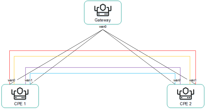
Full-Mesh topology
An example of the Partial-Mesh topology is shown in the figure below. This topology is used when direct links between some CPE devices may be undesirable, for example, for administrative reasons, or impossible for technical reasons. In this topology, the network administrator can group devices in such a way that devices in the same group communicate directly with each other, while communication with devices from other groups happens through a transit device.
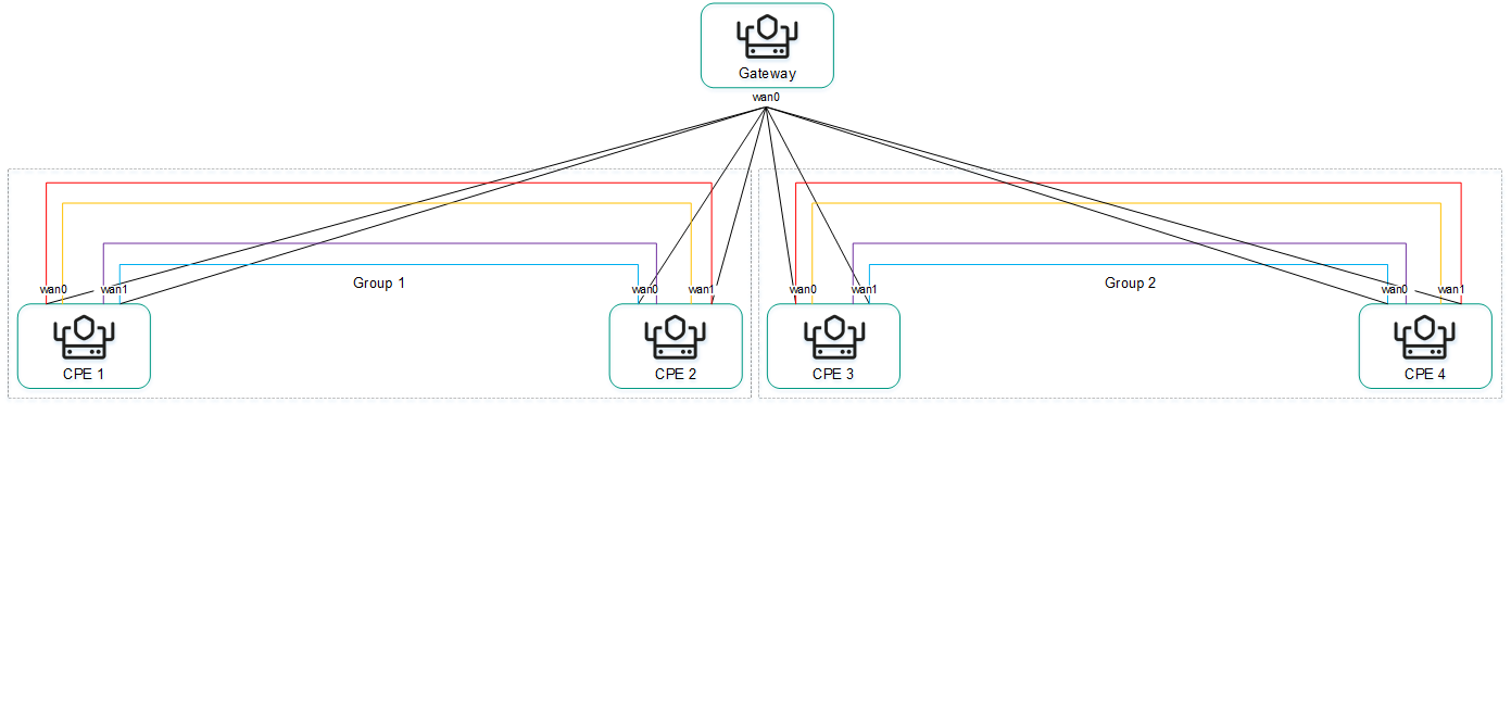
Partial-Mesh topology
A CPE device can belong to multiple groups at the same time, as shown in the figure below.
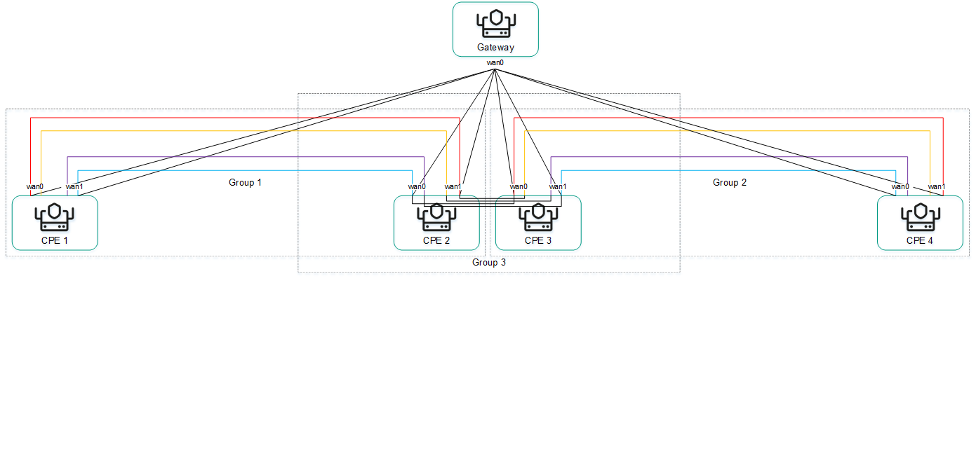
Partial-Mesh topology, CPE devices in multiple groups
When creating direct links between CPE devices, depending on the type of connectivity of the devices through physical channels, the following variants of overlay connectivity are possible:
- All physical communication channels have direct IP connectivity to each other (see the figure below). Thanks to the connectivity within the internet, CPE devices can establish the maximum number of direct links among themselves.
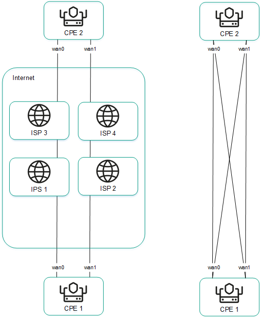
Full physical connectivity between CPE devices
- Physical communication channels have partial connectivity (see the figure below). In the example shown in the figure below, the internet cloud and the MPLS cloud are not interconnected, so links can only be established through WAN interfaces belonging to the same cloud. CPE1:WAN0 → CPE2:WAN1 and CPE1:WAN1 → CPE2:WAN0 links cannot be created.
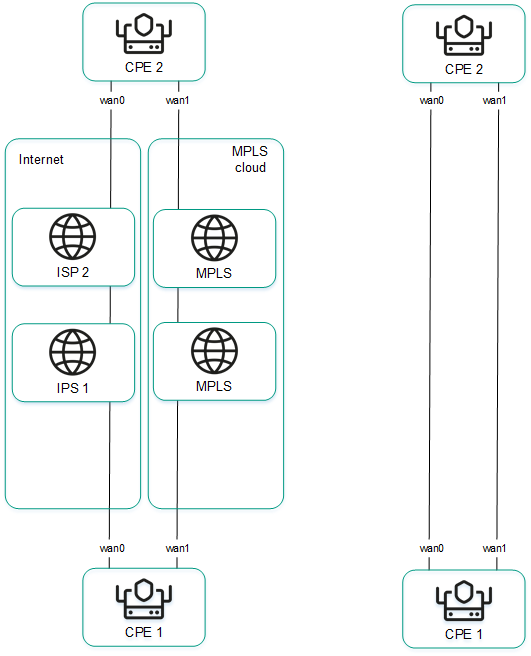
Partial physical connectivity between CPE devices
Other overlay network connectivity scenarios are also possible if IP connectivity between WAN interfaces of CPE devices within the same cloud is impossible for other reasons, for example, when using an MPLS topology that does not support direct communication between devices, or due to the presence of NAT/PAT or ACL on the internet.
Page top
Creating a Hub-and-Spoke topology
A Hub-and-Spoke topology is built using roles that you assign to CPE devices. You can assign the role of a standard CPE device or an SD-WAN Gateway. Standard devices establish links with each other through SD-WAN Gateways.
By default, all devices are assigned the standard device role. To build a Hub-and-Spoke topology, at least one device must be assigned the SD-WAN Gateway role.
You can assign this role to an individual CPE device or to all devices that use the CPE template. To build a Hub-and-Spoke topology, use the following instructions:
- Assigning a role to an individual CPE device.
To assign a role to an individual CPE device:
- In the menu, go to the Infrastructure section.
The SD-WAN infrastructure management page is displayed. By default, the Network resources tab is selected, which displays the table of SD-WAN Controllers.
- Click Management next to the SD-WAN Controller and in the drop-down list, select Configuration menu.
This opens the SD-WAN Controller configuration menu. By default, you are taken to the Controller nodes section, which displays a table of Controller nodes.
- Go to the Topology tags section.
The topology tag settings are displayed.
- In the Switch drop-down list, select the CPE device.
- In the Role drop-down list, select the role for the CPE device:
- CPE for a standard CPE device.
- Gateway for an SD-WAN Gateway.
- In the upper part of the page, click Save.
You can also assign a role in the CPE device configuration.
To assign a role in the CPE device configuration:
- In the menu, go to the SD-WAN section.
By default, the CPE subsection is displayed with a table of CPE devices.
- Click the CPE device.
The settings area is displayed in the lower part of the page. You can expand the settings area to fill the entire page by clicking the expand button
. - Select the Topology tab.
The topology tag settings are displayed.
- Select the Override check box to ignore the applied CPE template and make the settings in the selected tab editable. This check box is cleared by default.
- In the Switch drop-down list, select the CPE device.
- In the Role drop-down list, select the role for the CPE device:
- CPE for a standard CPE device.
- Gateway for an SD-WAN Gateway.
- In the upper part of the settings area, click Save to save the configuration of the CPE device.
- In the menu, go to the Infrastructure section.
- Assigning a role to all devices that use the CPE template.
To assign a role to all devices that use the CPE template:
- In the menu, go to the SD-WAN → CPE templates subsection.
A table of CPE templates is displayed.
- Click the CPE template.
The settings area is displayed in the lower part of the page. You can expand the settings area to fill the entire page by clicking the expand button
. - Select the Topology tab.
The topology tag settings are displayed.
- In the Role drop-down list, select a role for devices associated with the CPE template:
- CPE for a standard CPE device.
- Gateway for an SD-WAN Gateway.
- In the upper part of the settings area, click Save to save the configuration of the CPE template.
- In the menu, go to the SD-WAN → CPE templates subsection.
Creating Full-Mesh and Partial-Mesh topologies
Full-Mesh and Partial-Mesh topologies are built using topology tags that you assign to CPE devices. You can only assign topology tags to standard devices. If two devices are assigned the same topology tag, a link is automatically created between them.
In a Full-Mesh topology, all devices are assigned the same topology tag.
In a Partial-Mesh topology, devices are divided into groups based on the tags assigned to them, and communication between the devices happens through transit devices, which are devices to which tags from all groups are assigned.
You can assign a topology tag to an individual CPE device or to all devices that use the CPE template. To assign topology tags, use the following instructions:
- Assigning a topology tag to an individual CPE device.
To assign a topology tag to an individual CPE device:
- In the menu, go to the Infrastructure section.
The SD-WAN infrastructure management page is displayed. By default, the Network resources tab is selected, which displays the table of SD-WAN Controllers.
- Click Management next to the SD-WAN Controller and in the drop-down list, select Configuration menu.
This opens the SD-WAN Controller configuration menu. By default, you are taken to the Controller nodes section, which displays a table of Controller nodes.
- Go to the Topology tags section.
The topology tag settings are displayed.
- In the Switch drop-down list, select the CPE device.
- Make sure that in the Role drop-down list, the CPE option is selected. The Gateway is not used to build Full-Mesh and Partial-Mesh topologies.
- If you want to build a Partial-Mesh topology, to use a device as a transit device, select the Transit CPE check box. Transit devices are necessary to connect groups of devices together and make it possible for other devices to establish links through these transit devices.
- In the Topology tags field, enter a topology tag and click the add button . Devices with the same topology tags automatically establish direct links with each other.
To build a Full-Mesh topology, assign the same topology tags to all devices.
To build a Partial-Mesh topology, assign topology tags to devices based on which group they belong to. Also assign all tags used in the topology to the transit device to make sure that all device groups are added to the topology.
The topology tag is assigned and displayed below the Topology tags field.
- In the upper part of the page, click Save.
You can also assign a topology tag in the CPE device configuration.
To assign a topology tag in the CPE device configuration:
- In the menu, go to the SD-WAN section.
By default, the CPE subsection is displayed with a table of CPE devices.
- Click the CPE device.
The settings area is displayed in the lower part of the page. You can expand the settings area to fill the entire page by clicking the expand button
. - Select the Topology tab.
The topology tag settings are displayed.
- Select the Override check box to ignore the applied CPE template and make the settings in the selected tab editable. This check box is cleared by default.
- In the Switch drop-down list, select the CPE device.
- Make sure that in the Role drop-down list, the CPE option is selected. The Gateway is not used to build Full-Mesh and Partial-Mesh topologies.
- If you want to build a Partial-Mesh topology, to use a device as a transit device, select the Transit CPE check box. Transit devices are necessary to connect groups of devices together and make it possible for other devices to establish links through these transit devices.
- In the Topology tags field, enter a topology tag and click the add button . Devices with the same topology tags automatically establish direct links with each other.
To build a Full-Mesh topology, assign the same topology tags to all devices.
To build a Partial-Mesh topology, assign topology tags to devices based on which group they belong to. Also assign all tags used in the topology to the transit device to make sure that all device groups are added to the topology.
The topology tag is assigned and displayed below the Topology tags field.
- In the upper part of the settings area, click Save to save the configuration of the CPE device.
- In the menu, go to the Infrastructure section.
- Assigning a topology tag to all devices that use the CPE template.
To assign a topology tag to all devices that use the CPE template:
- In the menu, go to the SD-WAN → CPE templates subsection.
A table of CPE templates is displayed.
- Click the CPE template.
The settings area is displayed in the lower part of the page. You can expand the settings area to fill the entire page by clicking the expand button
. - Select the Topology tab.
The topology tag settings are displayed.
- Make sure that in the Role drop-down list, the CPE option is selected. The Gateway is not used to build Full-Mesh and Partial-Mesh topologies.
- If you want to build a Partial-Mesh topology, to use a device as a transit device, select the Transit CPE check box. Transit devices are necessary to connect groups of devices together and make it possible for other devices to establish links through these transit devices.
- In the Topology tags field, enter a topology tag and click the add button . Devices with the same topology tags automatically establish direct links with each other.
To build a Full-Mesh topology, assign the same topology tags to all devices.
To build a Partial-Mesh topology, assign topology tags to devices based on which group they belong to. Also assign all tags used in the topology to the transit device to make sure that all device groups are added to the topology.
The topology tag is assigned and displayed below the Topology tags field.
- In the upper part of the settings area, click Save to save the configuration of the CPE template.
- In the menu, go to the SD-WAN → CPE templates subsection.
If necessary, you can remove a topology tag from an individual CPE device or from all devices that use the CPE template. To remove topology tags, use the following instructions:
- Removing a topology tag from an individual CPE device.
To remove a topology tag from an individual CPE device:
- In the menu, go to the Infrastructure section.
The SD-WAN infrastructure management page is displayed. By default, the Network resources tab is selected, which displays the table of SD-WAN Controllers.
- Click Management next to the SD-WAN Controller and in the drop-down list, select Configuration menu.
This opens the SD-WAN Controller configuration menu. By default, you are taken to the Controller nodes section, which displays a table of Controller nodes.
- Go to the Topology tags section.
The topology tag settings are displayed.
- In the Switch drop-down list, select the CPE device.
- Click the delete button next to the topology tag.
The topology tag is removed and is no longer displayed.
- In the upper part of the page, click Save.
You can also remove a topology tag in the CPE device configuration.
To remove a topology tag in the CPE device configuration:
- In the menu, go to the SD-WAN section.
By default, the CPE subsection is displayed with a table of CPE devices.
- Click the CPE device.
The settings area is displayed in the lower part of the page. You can expand the settings area to fill the entire page by clicking the expand button
. - Select the Topology tab.
The topology tag settings are displayed.
- Select the Override check box to ignore the applied CPE template and make the settings in the selected tab editable. This check box is cleared by default.
- Click the delete button next to the topology tag.
The topology tag is removed and is no longer displayed.
- In the upper part of the settings area, click Save to save the configuration of the CPE device.
- In the menu, go to the Infrastructure section.
- Removing a topology tag from all devices that use the CPE template.
To remove a topology tag from all devices that use the CPE template:
- In the menu, go to the SD-WAN → CPE templates subsection.
A table of CPE templates is displayed.
- Click the CPE template.
The settings area is displayed in the lower part of the page. You can expand the settings area to fill the entire page by clicking the expand button
. - Select the Topology tab.
The topology tag settings are displayed.
- Click the delete button next to the topology tag.
The topology tag is removed and is no longer displayed.
- In the upper part of the settings area, click Save to save the configuration of the CPE template.
- In the menu, go to the SD-WAN → CPE templates subsection.
Quality of Service (QoS)
A Quality of Service (QoS) policy ensures data transfer in accordance with the requirements set for traffic classes. In Kaspersky SD-WAN, the following components contribute to the quality of service:
- Traffic classes are used to queue and prioritize traffic. For example, one of the classes can be used for real-time traffic that requires minimizing packet loss.
- Traffic classifiers determine whether or not to trust DSCP values (Differentiated Services Code Point) set in the traffic packet header fields; they also map DSCP values to traffic classifiers.
- QoS rules determine whether the bandwidth of traffic processed by traffic classifiers is limited.
- Constraints are used in transport services for SLA compliance. You can create two types of constraints:
- Manual TE constraints are used to add Manual-TE paths to transport services. When configuring this type of constraints, you can enable the use of an Auto-SPF path if Manual-TE paths are not available.
- Threshold constraints are used to build Auto-TE routes in transport services based on threshold values of monitoring indicators.
If a link used in a transport service reaches the threshold values of the selected monitoring indicators, this link is completely or partially excluded from the Auto-TE path calculation. Partially excluded links can be taken into account when calculating the Auto-TE path if there are no alternative links satisfying the constraint.
For example, you can create a constraint that completely excludes from the Auto-TE path calculation those links that have reached the packet loss threshold. Thus, in a transport service that uses this constraint, traffic only travels through links that have low packet loss.
- Traffic classification rules are used to identify traffic with particular values of the L2 – L4 header fields, as well as traffic of specified applications, in the overall stream of traffic. For each traffic classification rule, you must specify a sequence number and select a default action, which allows or prohibits further routing of the traffic. Classification rules are added to traffic filters.
- Traffic filters are used to ensure security by blocking excessive or dangerous traffic, to classify traffic, and to comply with SLA requirements for applications. Each filter consists of one or more traffic classification rules.
A maximum of 8 traffic queues can be used on the WAN and LAN interfaces. For each queue, you must specify the minimum and maximum bandwidth as a percentage of the total bandwidth set for the interface as a whole. The sum total of all minimum bandwidth values specified for queues may not exceed 100%.
The queues are strict priority and unreserved bandwidth is first offered to traffic from the higher-priority queue. Each queue is guaranteed certain minimum bandwidth in accordance with its specified minimum bandwidth value. An upper limit on the maximum bandwidth for higher-priority queues is necessary to allow traffic from lower-priority queues to still be transmitted.
You can configure queues when creating or editing WAN interfaces. Due to the fact that Kaspersky SD-WAN does not support creating LAN interfaces, queues can only be configured for LAN interfaces that already exist.
Service providers can use different QoS policies to mark queues in their networks and meet the requirements of service level agreements (SLA) for the passage of client traffic. Therefore, when CPE devices are connected to communication channels of different service providers, the CPE devices can flexibly relabel traffic of different queues for each WAN interface. To configure relabelling, you must change the value of the type of service (hereinafter also referred to as ToS) when configuring queues on the SD-WAN interface.
You can edit only the ToS values of the external (link) headers of traffic packets going out of the WAN interfaces. ToS values of internal traffic packet headers cannot be edited.
Default traffic classes
Kaspersky SD-WAN has default traffic classes for processing and filtering different types of traffic (see the table below). You can create new traffic classes or modify existing ones. Default traffic classes are suitable for most deployment scenarios, and we do not recommend changing them.
Default traffic classes
Name |
Internal tag |
Queue |
KOver |
Exclude when computing path |
|---|---|---|---|---|
Best effort |
0 |
0 |
0 |
Yes |
Business normal |
1 |
1 |
1 |
No |
Business critical |
2 |
2 |
1 |
No |
Video |
3 |
3 |
1 |
No |
Conference |
4 |
4 |
1 |
No |
Signaling |
5 |
5 |
1 |
No |
Real time |
6 |
6 |
1 |
No |
Network control |
7 |
7 |
1 |
No |
The default settings presented in the table are described in the instructions for creating and editing traffic classes.
Page top
Creating or editing traffic classes
Default traffic classes are suitable for most Kaspersky SD-WAN deployment scenarios, and we do not recommend changing them.
You can create or modify 4 to 8 traffic classes in an SD-WAN instance template, or edit traffic classes in an already deployed SD-WAN instance. If you create traffic classes in an SD-WAN instance template and use that template to deploy an individual instance, the same traffic classes are automatically created in the deployed instance.
To create and edit traffic classes, use the following instructions:
- Creating traffic classes in an SD-WAN instance template.
In one of the traffic classes you create, you must put control traffic that is used to manage the SD-WAN infrastructure and configure its components, including setting up and managing links, exchanging routing information between devices, and monitoring the status and performance of the network. We recommend to assign control traffic to the highest priority to ensure efficient and reliable functioning of the network.
To create traffic classes in an SD-WAN instance template:
- In the menu, go to the SD-WAN → SD-WAN instance templates subsection.
A table of SD-WAN instance templates is displayed.
- Click the SD-WAN Instance template.
The settings area is displayed in the lower part of the page. You can expand the settings area to fill the entire page by clicking the expand button
. - Select the Traffic classes tab.
A table of traffic classes is displayed.
- Click Edit.
- This opens a window; in that window, click + Traffic class to add a traffic class.
- In the Name column, enter a name for the traffic class.
- In the Queue column, select the number of the queue into which you want to place traffic of the selected class. The higher the value, the higher the priority of the traffic class. You cannot specify the same priority for multiple traffic classes.
- In the KOver column, select the overcommitment ratio of the traffic bandwidth, which sets the multiplier by which the bandwidth dedicated to the class can be increased if the total bandwidth is not fully utilized.
- If you need to ignore the bandwidth available to the traffic class when calculating the route, select the Exclude when computing path check box. When this check box is selected, you cannot select the KOver ratio for the traffic class. By default, the check box is selected for the last traffic class in the table (Best effort).
- In the Default traffic class drop-down list, select the class in which you want to place all traffic that is not included in other classes. By default, the last traffic class in the table is selected (Best effort).
- In the Control traffic class drop-down list, select the class in which you want to place control traffic. By default, the first traffic class in the table is selected (Network control).
- In the Maximum reserved bandwidth (%) drop-down list, select the percentage of the maximum traffic transfer rate that can be available for one of the created traffic classes. Range of values: 10 to 90. The default setting is 90.
- Click Ok.
- In the upper part of the settings area, click Save to save the configuration of the SD-WAN instance template.
- In the menu, go to the SD-WAN → SD-WAN instance templates subsection.
- Editing traffic classes in an SD-WAN instance template.
To edit a traffic class in an SD-WAN instance template:
- In the menu, go to the SD-WAN → SD-WAN instance templates subsection.
A table of SD-WAN instance templates is displayed.
- Click the SD-WAN Instance template.
The settings area is displayed in the lower part of the page. You can expand the settings area to fill the entire page by clicking the expand button
. - Select the Traffic classes tab.
A table of traffic classes is displayed.
- Click Edit.
- This opens a window; in that window, edit the settings that you want to change. For a description of the settings, refer to the instructions for creating traffic classes in an SD-WAN instance template.
- Click Ok.
- In the upper part of the settings area, click Save to save the configuration of the SD-WAN instance template.
- In the menu, go to the SD-WAN → SD-WAN instance templates subsection.
- Editing traffic classes in an already deployed SD-WAN instance.
Creating a traffic classifier
You can create a traffic classifier in an already deployed SD-WAN instance or in an SD-WAN instance template. If you create a traffic classifier in an SD-WAN instance template and use that template to deploy an individual instance, the same traffic classifier is automatically created in the deployed instance.
To create a traffic classifier, use the following instructions:
- Creating a traffic classifier in an already deployed SD-WAN instance.
- Creating a traffic classifier in an SD-WAN instance template.
To create a traffic classifier in an SD-WAN instance template:
- In the menu, go to the SD-WAN → SD-WAN instance templates subsection.
A table of SD-WAN instance templates is displayed.
- Click the SD-WAN Instance template.
The settings area is displayed in the lower part of the page. You can expand the settings area to fill the entire page by clicking the expand button
. - Select the Traffic classifiers tab.
A table of traffic classes is displayed.
- Click + Classifier.
- This opens a window; in that window, in the Name field, enter the name of the traffic classifier.
- In the Type list, select one of the following values:
- Trust is a classifier that trusts the DSCP values set in the header fields of traffic packets. This is the default setting.
- Untrust is a classifier that does not trust the DSCP values set in the traffic packet header fields.
- If you selected Trust in the Type list, map the classes to DSCP values in the traffic packet headers:
- In the Traffic class column, select the class into which you want to place the traffic.
- In the External tag column, click Select next to the package header that must contain the necessary DSCP value.
- Select the check boxes next to the displayed DSCP values that must be present in the packet header for the traffic to be placed in the selected class.
- Click Ok.
- If in the Type lust you selected Untrust, select the class in which you want to place all traffic in the Traffic class class drop-down list.
- Click Create.
The traffic classifier is created and displayed in the table.
- In the upper part of the settings area, click Save to save the configuration of the SD-WAN instance template.
- In the menu, go to the SD-WAN → SD-WAN instance templates subsection.
Editing a traffic classifier
You can edit a traffic classifier in an already deployed SD-WAN instance or in an SD-WAN instance template. For a description of the settings, see the instructions for creating a traffic classifier.
To edit a traffic classifier in an already deployed SD-WAN instance:
- In the menu, go to the Infrastructure section.
The SD-WAN infrastructure management page is displayed. By default, the Network resources tab is selected, which displays the table of SD-WAN Controllers.
- Click Management next to the SD-WAN Controller and in the drop-down list, select Configuration menu.
This opens the SD-WAN Controller configuration menu. By default, you are taken to the Controller nodes section, which displays a table of Controller nodes.
- Go to the QoS section.
The Traffic classes tab, which is selected by default, displays the table of traffic classes.
- Select the Traffic classifiers tab.
A table of traffic classes is displayed.
- Click Management next to the traffic classifier and in the drop-down list, select Edit.
- This opens a window; in that window, edit the settings that you want to change.
- Click Save.
To edit a traffic classifier in an SD-WAN instance template:
- In the menu, go to the SD-WAN → SD-WAN instance templates subsection.
A table of SD-WAN instance templates is displayed.
- Click the SD-WAN Instance template.
The settings area is displayed in the lower part of the page. You can expand the settings area to fill the entire page by clicking the expand button
. - Select the Traffic classifiers tab.
A table of traffic classes is displayed.
- Click Management next to the traffic classifier and in the drop-down list, select Edit.
- This opens a window; in that window, edit the settings that you want to change.
- Click Save.
- In the upper part of the settings area, click Save to save the configuration of the SD-WAN instance template.
Deleting a traffic classifier
You can delete a traffic classifier in an already deployed SD-WAN instance or in an SD-WAN instance template. Deleted traffic classifiers cannot be restored.
To delete a traffic classifier in an already deployed SD-WAN instance:
- In the menu, go to the Infrastructure section.
The SD-WAN infrastructure management page is displayed. By default, the Network resources tab is selected, which displays the table of SD-WAN Controllers.
- Click Management next to the SD-WAN Controller and in the drop-down list, select Configuration menu.
This opens the SD-WAN Controller configuration menu. By default, you are taken to the Controller nodes section, which displays a table of Controller nodes.
- Go to the QoS section.
The Traffic classes tab, which is selected by default, displays the table of traffic classes.
- Select the Traffic classifiers tab.
A table of traffic classes is displayed.
- Click Management next to the traffic classifier and in the drop-down list, select Delete.
- In the confirmation window, click Delete.
The traffic classifier is deleted and is no longer displayed in the table.
To delete a traffic classifier in an SD-WAN instance template:
- In the menu, go to the SD-WAN → SD-WAN instance templates subsection.
A table of SD-WAN instance templates is displayed.
- Click the SD-WAN Instance template.
The settings area is displayed in the lower part of the page. You can expand the settings area to fill the entire page by clicking the expand button
. - Select the Traffic classifiers tab.
A table of traffic classes is displayed.
- Click Management next to the traffic classifier and in the drop-down list, select Delete.
The traffic classifier is deleted and is no longer displayed in the table.
- In the upper part of the settings area, click Save to save the configuration of the SD-WAN instance template.
Creating a QoS rule
You can create a QoS rule in an already deployed SD-WAN instance or in an SD-WAN instance template. If you create a QoS rule in an SD-WAN instance template and use that template to deploy an individual instance, the same QoS rule is automatically created in the deployed instance.
Before creating a QoS rule, you must create a traffic classifier.
To create a QoS rule, use the following instructions:
- Creating a QoS rule in an already deployed SD-WAN instance.
- Creating a QoS rule in an SD-WAN instance template.
To create a QoS rule in an SD-WAN instance template:
- In the menu, go to the SD-WAN → SD-WAN instance templates subsection.
A table of SD-WAN instance templates is displayed.
- Click the SD-WAN Instance template.
The settings area is displayed in the lower part of the page. You can expand the settings area to fill the entire page by clicking the expand button
. - Select the QoS rules tab.
A table of QoS rules is displayed.
- Click + QoS rule.
- This opens a window; in that window, in the Name field, enter the name of the QoS rule.
- In the Classifier drop-down list, select the previously created traffic classifier that you want to use in the QoS rule.
- Configure traffic bandwidth limiting:
- If you do not want to limit the bandwidth of traffic processed by the previously selected classifier, select the Unlimited check box.
- If you want to limit the bandwidth of traffic processed by the previously selected classifier, clear the Unlimited check box.
This check box is selected by default.
QoS rules that do not limit traffic bandwidth provide users with the highest network performance, especially when dealing with applications and services with high bandwidth requirements. However, if your network is not resource-rich, bandwidth limiting may help avoid issues with congestion, performance, and traffic filtering for applications that have different priorities.
- If you cleared the Unlimited check box, configure the traffic bandwidth limiting settings:
- In the MBR field, enter the maximum bit rate. The default setting is
1. - In the Speed type drop-down list, select the units of measurement for the maximum bit rate:
- Kbit/s (selected by default)
- Mbit/s
- Gbit/s
- If you have selected a classifier of the Trust type in the Classifier drop-down list, in the Classifier drop-down list, in the Maximum reserved bandwidth (%) column, specify the percentage of the total bit rate available to each class. The sum total of the values specified for each class must equal 100%.
- In the MBR field, enter the maximum bit rate. The default setting is
- Click Create.
The QoS rule is created and displayed in the table.
- In the upper part of the settings area, click Save to save the configuration of the SD-WAN instance template.
- In the menu, go to the SD-WAN → SD-WAN instance templates subsection.
Editing a QoS rule
You can edit a QoS rule in an already deployed SD-WAN instance or in an SD-WAN instance template. For a description of the settings, see the instructions for creating a QoS rule.
To edit a QoS rule in an already deployed SD-WAN instance:
- In the menu, go to the Infrastructure section.
The SD-WAN infrastructure management page is displayed. By default, the Network resources tab is selected, which displays the table of SD-WAN Controllers.
- Click Management next to the SD-WAN Controller and in the drop-down list, select Configuration menu.
This opens the SD-WAN Controller configuration menu. By default, you are taken to the Controller nodes section, which displays a table of Controller nodes.
- Go to the QoS section.
The Traffic classes tab, which is selected by default, displays the table of traffic classes.
- Select the QoS rules tab.
A table of QoS rules is displayed.
- Click Management next to the QoS rule and in the drop-down list, select Edit.
- This opens a window; in that window, edit the settings that you want to change.
- Click Save.
To edit a QoS rule in an SD-WAN instance template:
- In the menu, go to the SD-WAN → SD-WAN instance templates subsection.
A table of SD-WAN instance templates is displayed.
- Click the SD-WAN Instance template.
The settings area is displayed in the lower part of the page. You can expand the settings area to fill the entire page by clicking the expand button
. - Select the QoS rules tab.
A table of QoS rules is displayed.
- Click Management next to the QoS rule and in the drop-down list, select Edit.
- This opens a window; in that window, edit the settings that you want to change.
- Click Save.
- In the upper part of the settings area, click Save to save the configuration of the SD-WAN instance template.
Deleting a QoS rule
You can delete a QoS rule in an already deployed SD-WAN instance or in an SD-WAN instance template. Deleted QoS rules cannot be restored.
To delete a QoS rule in an already deployed SD-WAN instance:
- In the menu, go to the Infrastructure section.
The SD-WAN infrastructure management page is displayed. By default, the Network resources tab is selected, which displays the table of SD-WAN Controllers.
- Click Management next to the SD-WAN Controller and in the drop-down list, select Configuration menu.
This opens the SD-WAN Controller configuration menu. By default, you are taken to the Controller nodes section, which displays a table of Controller nodes.
- Go to the QoS section.
The Traffic classes tab, which is selected by default, displays the table of traffic classes.
- Select the QoS rules tab.
A table of QoS rules is displayed.
- Click Management next to the QoS rule and in the drop-down list, select Delete.
- In the confirmation window, click Delete.
The QoS rule is deleted and is no longer displayed in the table.
To delete a QoS rule in an SD-WAN instance template:
- In the menu, go to the SD-WAN → SD-WAN instance templates subsection.
A table of SD-WAN instance templates is displayed.
- Click the SD-WAN Instance template.
The settings area is displayed in the lower part of the page. You can expand the settings area to fill the entire page by clicking the expand button
. - Select the QoS rules tab.
A table of QoS rules is displayed.
- Click Management next to the QoS rule and in the drop-down list, select Delete.
The QoS rule is deleted and is no longer displayed in the table.
- In the upper part of the settings area, click Save to save the configuration of the SD-WAN instance template.
Creating a Manual-TE constraint
Before creating a Manual-TE constraint, you must create Manual-TE paths.
To create a Manual-TE constraint:
- In the menu, go to the Infrastructure section.
The SD-WAN infrastructure management page is displayed. By default, the Network resources tab is selected, which displays the table of SD-WAN Controllers.
- Click Management next to the SD-WAN Controller and in the drop-down list, select Configuration menu.
This opens the SD-WAN Controller configuration menu. By default, you are taken to the Controller nodes section, which displays a table of Controller nodes.
- Go to the Constraints section.
A table of Manual-TE constraints is displayed.
- In the upper part of the page, click + Manual-TE constraint.
- This opens a window; in that window, in the Name field, enter the name of the Manual-TE constraint.
- Select the Use Manual-TE path check box next to the Manual-TE paths that you want to add to the constraint. By default, the check boxes are cleared and no paths are added to the constraint.
- To allow an Auto-SPF path to be used when no Manual-TE paths are available, select the Ignore if no constrained path is found check box next to the relevant Manual-TE paths. The check box can be selected only for paths that have the Use Manual-TE path check box selected. By default, the check boxes are cleared and Auto-SPF cannot be used as an alternative for all paths.
- Click Create.
The Manual-TE constraint is created and displayed in the table.
Now you can specify the Manual-TE constraint in transport service settings to add Manual-TE paths contained in the constraint to the transport service.
Page top
Editing a Manual-TE constraint
To edit a Manual-TE constraint:
- In the menu, go to the Infrastructure section.
The SD-WAN infrastructure management page is displayed. By default, the Network resources tab is selected, which displays the table of SD-WAN Controllers.
- Click Management next to the SD-WAN Controller and in the drop-down list, select Configuration menu.
This opens the SD-WAN Controller configuration menu. By default, you are taken to the Controller nodes section, which displays a table of Controller nodes.
- Go to the Constraints section.
A table of Manual-TE constraints is displayed.
- Click Management next to the Manual-TE constraint and in the drop-down list, select Edit.
- This opens a window; in that window, edit the settings that you want to change. For a description of the settings, see the instructions for creating a Manual-TE constraint.
- Click Save.
Deleting a Manual-TE constraint
Deleted Manual-TE constraints cannot be restored.
To delete a Manual-TE constraint:
- In the menu, go to the Infrastructure section.
The SD-WAN infrastructure management page is displayed. By default, the Network resources tab is selected, which displays the table of SD-WAN Controllers.
- Click Management next to the SD-WAN Controller and in the drop-down list, select Configuration menu.
This opens the SD-WAN Controller configuration menu. By default, you are taken to the Controller nodes section, which displays a table of Controller nodes.
- Go to the Constraints section.
A table of Manual-TE constraints is displayed.
- Click Management next to the Manual-TE constraint and in the drop-down list, select Delete.
- In the confirmation window, click Delete.
The Manual-TE constraint is deleted and is no longer displayed in the table.
Page top
Creating a threshold constraint
Before creating a threshold constraint, you must enable monitoring on links.
To create a threshold constraint:
- In the menu, go to the Infrastructure section.
The SD-WAN infrastructure management page is displayed. By default, the Network resources tab is selected, which displays the table of SD-WAN Controllers.
- Click Management next to the SD-WAN Controller and in the drop-down list, select Configuration menu.
This opens the SD-WAN Controller configuration menu. By default, you are taken to the Controller nodes section, which displays a table of Controller nodes.
- Go to the Constraints section.
A table of Manual-TE constraints is displayed.
- Select the Thresholds tab.
A table of threshold constraints is displayed.
- In the upper part of the page, click + Threshold constraint.
- This opens a window; in that window, in the Name field, enter the name of the threshold constraint.
- Select the Do not use tunnels with threshold reached check box next to monitoring indicators to have the threshold constraint exclude links that have reached the threshold value of these indicators from the Auto-TE path calculation. By default, the Do not use tunnels with threshold reached check box is cleared and no monitoring indicators are used to exclude links.
- If necessary, select the Ignore if no constrained path is found check box next to the monitoring indicators to let the constraint include links that have reached threshold values of these indicators in the Auto-TE path calculation when alternative links do not exist. The check box can be selected only for links that have the Do not use tunnels with threshold reached check box selected.
By default, the Ignore if no constrained path is found check box is cleared and the constraint excludes all links that have reached the threshold values of the selected monitoring indicators from the Auto-TE path calculation.
- Click Create.
The constraint is created and displayed in the table.
You can specify the constraint in transport service settings to use it for automatic calculation of the path.
Page top
Editing a threshold constraint
To edit a threshold constraint:
- In the menu, go to the Infrastructure section.
The SD-WAN infrastructure management page is displayed. By default, the Network resources tab is selected, which displays the table of SD-WAN Controllers.
- Click Management next to the SD-WAN Controller and in the drop-down list, select Configuration menu.
This opens the SD-WAN Controller configuration menu. By default, you are taken to the Controller nodes section, which displays a table of Controller nodes.
- Go to the Constraints section.
A table of Manual-TE constraints is displayed.
- Select the Thresholds tab.
A table of threshold constraints is displayed.
- Click Management next to the threshold constraint and in the drop-down list, select Edit.
- This opens a window; in that window, edit the settings that you want to change. For a description of the settings, see the instructions for creating a threshold constraint.
- Click Save.
Deleting a threshold constraint
Deleted threshold constraints cannot be restored.
To delete a threshold constraint:
- In the menu, go to the Infrastructure section.
The SD-WAN infrastructure management page is displayed. By default, the Network resources tab is selected, which displays the table of SD-WAN Controllers.
- Click Management next to the SD-WAN Controller and in the drop-down list, select Configuration menu.
This opens the SD-WAN Controller configuration menu. By default, you are taken to the Controller nodes section, which displays a table of Controller nodes.
- Go to the Constraints section.
A table of Manual-TE constraints is displayed.
- Select the Thresholds tab.
A table of threshold constraints is displayed.
- Click Management next to the threshold constraint and in the drop-down list, select Delete.
- In the confirmation window, click Delete.
The threshold constraint is deleted and is no longer displayed in the table.
Page top
Traffic classification rules
This section describes how to configure traffic classification rules.
Creating a traffic classification rule
To create a traffic classification rule:
- In the menu, go to the Infrastructure section.
The SD-WAN infrastructure management page is displayed. By default, the Network resources tab is selected, which displays the table of SD-WAN Controllers.
- Click Management next to the SD-WAN Controller and in the drop-down list, select Configuration menu.
This opens the SD-WAN Controller configuration menu. By default, you are taken to the Controller nodes section, which displays a table of Controller nodes.
- Go to the Traffic filters section.
A table of traffic filters is displayed.
- Select the Rules tab.
A table of traffic classification rules is displayed.
- In the upper part of the page, click + Qualification rule.
- This opens a window; in that window, in the Name field, enter the name of the traffic classification rule.
- On the L2 fields tab, select the check boxes next to the L2 fields whose values the rule must use to identify traffic in the overall data stream. If the check box is selected, enter or select the required value. You can use the values of the following fields to identify traffic:
- Outer VLAN ID – range of values: 1 to 2,094.
- Outer VLAN PCP — range of values: 0 to 7.
- Source MAC.
- Source MAC mask.
- Destination MAC.
- Destination MAC mask.
- Ethertype — possible values:
- 0x0800 (selected by default)
- 0x86dd
- 0x0806
- On the L3 fields tab, select the check boxes next to the L3 fields whose values the rule must use to identify traffic in the overall data stream. If the check box is selected, enter or select the required value. You can use the values of the following fields to identify traffic:
- Protocol — Possible values:
- IPv4
- IPv6
- Source IP — IPv4 address or IPv6 address depending on the selected protocol
- Source IP prefix length — Range of values for the IPv4 address: from 0 to 32; for IPv6 address: from 0 to 128
- Destination IP — IPv4 address or IPv6 address depending on the selected protocol
- Destination IP prefix length — Range of values for the IPv4 address: from 0 to 32; for IPv6 address: from 0 to 128
- DSCP
- TOS
- Protocol — Possible values:
- On the L4 fields tab, select the check boxes next to the L4 fields whose values the rule must use to identify traffic in the overall data stream. If the check box is selected, enter or select the required value. You can use the values of the following fields to identify traffic:
- IP protocol
- Source port list
- Destination port list
- ICMP type number
- On the DPI tab, select the application whose traffic the rule must identify in the overall data stream:
- Select the Application check box.
- In the drop-down list, select the application.
DPI (Deep Packet Inspection) classification is not supported for traffic generated by CPE devices.
- Click Create.
The traffic classification rule is created and displayed in the table.
You can use a traffic classification rule when creating a traffic filter.
Example of a created traffic classification rule: You can create a traffic classification rule with the following parameters:
|
Editing a traffic classification rule
To edit a traffic classification rule:
- In the menu, go to the Infrastructure section.
The SD-WAN infrastructure management page is displayed. By default, the Network resources tab is selected, which displays the table of SD-WAN Controllers.
- Click Management next to the SD-WAN Controller and in the drop-down list, select Configuration menu.
This opens the SD-WAN Controller configuration menu. By default, you are taken to the Controller nodes section, which displays a table of Controller nodes.
- Go to the Traffic filters section.
A table of traffic filters is displayed.
- Select the Rules tab.
A table of traffic classification rules is displayed.
- Click Management next to the traffic classification rule and in the drop-down list, select Edit.
- This opens a window; in that window, edit the settings that you want to change. For a description of the settings, see the instructions for creating a traffic classification rule.
- Click Save.
Deleting a traffic classification rule
Deleted traffic classification rules cannot be restored.
To delete a traffic classification rule:
- In the menu, go to the Infrastructure section.
The SD-WAN infrastructure management page is displayed. By default, the Network resources tab is selected, which displays the table of SD-WAN Controllers.
- Click Management next to the SD-WAN Controller and in the drop-down list, select Configuration menu.
This opens the SD-WAN Controller configuration menu. By default, you are taken to the Controller nodes section, which displays a table of Controller nodes.
- Go to the Traffic filters section.
A table of traffic filters is displayed.
- Select the Rules tab.
A table of traffic classification rules is displayed.
- Click Management next to the traffic classification rule and in the drop-down list, select Delete.
- In the confirmation window, click Delete.
The traffic classification rule is deleted and is no longer displayed in the table.
Page top
Creating a traffic filter
Before creating a traffic filter, you must create at least one traffic classification rule.
To create a traffic filter:
- In the menu, go to the Infrastructure section.
The SD-WAN infrastructure management page is displayed. By default, the Network resources tab is selected, which displays the table of SD-WAN Controllers.
- Click Management next to the SD-WAN Controller and in the drop-down list, select Configuration menu.
This opens the SD-WAN Controller configuration menu. By default, you are taken to the Controller nodes section, which displays a table of Controller nodes.
- Go to the Traffic filters section.
A table of traffic filters is displayed.
- In the upper part of the page, click + Traffic fliter.
- This opens a window; in that window, in the Name field, enter the name of the traffic filter.
- In the Sequence field, enter the sequential number of the traffic classification rule. The rule with the lowest number is processed first. Range of values: 1 to 998. You cannot specify the same sequence number for multiple rules. The default setting is
10. - In the Qualification rule drop-down list, select a previously created traffic classification rule that you want to add to the filter.
- In the Action drop-down list, select the action that the traffic classification rule must apply to the traffic identified in the overall data stream:
- Permit — Allow further routing of the traffic. This is the default setting.
- Deny — Block further routing of the traffic.
- Click Add to add a previously created traffic classification rule to the filter. You can add multiple rules.
- In the Default action (if sequence=999) drop-down list, select the action that you want to apply to all other traffic:
- Permit — Allow further routing of the traffic. This is the default setting.
- Deny — Block further routing of the traffic.
- Click Create.
The traffic filter is created and displayed in the table.
You can use a traffic filter when creating transport services.
Editing a traffic filter
To edit a traffic filter:
- In the menu, go to the Infrastructure section.
The SD-WAN infrastructure management page is displayed. By default, the Network resources tab is selected, which displays the table of SD-WAN Controllers.
- Click Management next to the SD-WAN Controller and in the drop-down list, select Configuration menu.
This opens the SD-WAN Controller configuration menu. By default, you are taken to the Controller nodes section, which displays a table of Controller nodes.
- Go to the Traffic filters section.
A table of traffic filters is displayed.
- Click Management next to the traffic filter and in the drop-down list, select Edit.
- This opens a window; in that window, edit the settings that you want to change. For a description of the settings, see the instructions for creating a traffic filter.
- Click Save.
Deleting a traffic filter
Deleted traffic filters cannot be restored.
To delete a traffic filter:
- In the menu, go to the Infrastructure section.
The SD-WAN infrastructure management page is displayed. By default, the Network resources tab is selected, which displays the table of SD-WAN Controllers.
- Click Management next to the SD-WAN Controller and in the drop-down list, select Configuration menu.
This opens the SD-WAN Controller configuration menu. By default, you are taken to the Controller nodes section, which displays a table of Controller nodes.
- Go to the Traffic filters section.
A table of traffic filters is displayed.
- Click Management next to the traffic filter and in the drop-down list, select Delete.
- In the confirmation window, click Delete.
The traffic filter is deleted and is no longer displayed in the table.
Page top
Transport services
Transport services, which are mechanisms used to transfer traffic between remote locations, play a critical role in ensuring reliable, efficient, and secure communication throughout the SD-WAN infrastructure. Transport services are constructed on top of segments and consist of service interfaces.
Kaspersky SD-WAN supports creating the following transport services:
- Point-to-Point (P2P)
- Point-to-Multipoint (P2M)
- Multipoint-to-Multipoint (M2M)
When creating transport services, you can add reserve service interfaces. Reserve and primary service interfaces can be created on the same CPE device. A reserve service interface makes it possible to continue data transfer in the event of a failure of the primary service interface.
The settings of each individual transport service form a service topology that determines the type of connectivity between client devices connected to standard CPE devices and SD-WAN gateways.
Point-to-Point (P2P) transport service
Point-to-Point (E-line in the MEF classification, hereinafter also referred to as the P2P service) is a transport service within involves establishing a connection between two service interfaces of CPE devices on top of an Ethernet network for efficient and secure communication without the use of intermediate network devices. This is especially relevant when using applications that must transmit information in real time or exchange large files.
When creating a P2P service, you must specify the service interface that sends traffic (hereinafter referred to as the source interface) and the service interface that receives traffic (hereinafter referred to as the destination interface).
Creating a P2P service
Before creating a P2P service, you must complete the following steps:
- Activate CPE devices.
- Create a constraint (Manual-TE or threshold).
- Create service interfaces.
- Create a traffic filter.
- Create a QoS rule.
To create a P2P transport service:
- In the menu, go to the Infrastructure section.
The SD-WAN infrastructure management page is displayed. By default, the Network resources tab is selected, which displays the table of SD-WAN Controllers.
- Click Management next to the SD-WAN Controller and in the drop-down list, select Configuration menu.
This opens the SD-WAN Controller configuration menu. By default, you are taken to the Controller nodes section, which displays a table of Controller nodes.
- Go to the P2P services section.
A table of P2P services is displayed.
- In the upper part of the page, click + P2P service.
- This opens a window; in that window, in the Name field, enter the name of the transport service.
- In the Constraint drop-down list, select a previously created constraint that you want to add to the transport service.
- In the Balancing mode drop-down list, select the balancing mode for evenly distributing traffic among the links to prevent congestion of individual links and prevent performance issues for users:
- Per-flow — Balancing across flows (sessions). During transmission, flows are evenly distributed across the links. This is the default setting.
- Per-packet — Per-packet balancing. During transmission, packets are distributed evenly across the links.
- Broadcast — Packets are sent to all links simultaneously to prevent losses.
- If necessary, in the Description field, enter a brief description of the P2P service.
- In the Switch and Port drop-down lists on the left, select the CPE device and the service interface created on it that you want to use as the source interface.
- In the Switch and Port drop-down lists on the right, select the CPE device and the service interface created on it that you want to use as the destination interface.
- To display service interfaces that were previously added to transport services in the Port drop-down lists, select the Show used interfaces check box. This check box is cleared by default.
- To swap the values selected in the Port drop-down list for the source interface and the destination interface, select the Switch interfaces check box. This check box is cleared by default.
- If necessary, add a backup source interface through which traffic must be transmitted if the primary interface goes out of service:
- Select the Use backup interface check box. This check box is cleared by default.
- In the Backup switch and Backup port drop-down lists, select the CPE device and the service interface created on it that you want to use as the reserve service interface.
- To display service interfaces that were previously added to transport services in the Backup port drop-down list, select the Show used interfaces check box. This check box is cleared by default.
If the primary service interface goes back online, the transport service continues to use the reserve service interface.
- In the Inbound filter drop-down lists on the left and right, select the previously created traffic filter for the source and destination interfaces.
- In the QoS drop-down list, select the previously created QoS rule for the source interface.
- If you need to monitor the status of both service interfaces and when one of them becomes disabled, automatically disable the other, select the Propagate interface status check box. This check box is cleared by default. This check box cannot be selected when the Use backup interface check box is selected.
When the service interface that was disabled first goes back online, the second service interface that was automatically disabled also resumes operation. This functionality works only if the Access encapsulation type is used on the service interfaces. The encapsulation type is selected when creating the service interface.
- Click Create.
The P2P service is created and displayed in the table.
Page top
Editing a P2P service
To edit a P2P service:
- In the menu, go to the Infrastructure section.
The SD-WAN infrastructure management page is displayed. By default, the Network resources tab is selected, which displays the table of SD-WAN Controllers.
- Click Management next to the SD-WAN Controller and in the drop-down list, select Configuration menu.
This opens the SD-WAN Controller configuration menu. By default, you are taken to the Controller nodes section, which displays a table of Controller nodes.
- Go to the P2P services section.
A table of P2P services is displayed.
- Click Management next to the P2P service and in the drop-down list, select Edit.
- This opens a window; in that window, edit the settings that you want to change. For a description of the settings, see the instructions for creating a P2P service.
- Click Save.
Deleting a P2P service
Deleted P2P services cannot be restored
To delete a P2P service:
- In the menu, go to the Infrastructure section.
The SD-WAN infrastructure management page is displayed. By default, the Network resources tab is selected, which displays the table of SD-WAN Controllers.
- Click Management next to the SD-WAN Controller and in the drop-down list, select Configuration menu.
This opens the SD-WAN Controller configuration menu. By default, you are taken to the Controller nodes section, which displays a table of Controller nodes.
- Go to the P2P services section.
A table of P2P services is displayed.
- Click Management next to the P2P service and in the drop-down list, select Delete.
- If you need to delete the service interfaces added to the P2P service, select the Delete associated service interfaces check box in the confirmation window.
- Click Delete.
The P2P service is deleted and is no longer displayed in the table.
Page top
Viewing statistics of a P2P service
To view the statistics of a P2P service:
- In the menu, go to the Infrastructure section.
The SD-WAN infrastructure management page is displayed. By default, the Network resources tab is selected, which displays the table of SD-WAN Controllers.
- Click Management next to the SD-WAN Controller and in the drop-down list, select Configuration menu.
This opens the SD-WAN Controller configuration menu. By default, you are taken to the Controller nodes section, which displays a table of Controller nodes.
- Go to the P2P services section.
A table of P2P services is displayed.
- Click Management next to the P2P service and in the drop-down list, select Statistics.
This opens a window with statistics of the P2P service.
Page top
Configuring the display of devices in a P2P service topology
To configure the display of devices in a P2P service topology
- In the menu, go to the Infrastructure section.
The SD-WAN infrastructure management page is displayed. By default, the Network resources tab is selected, which displays the table of SD-WAN Controllers.
- Click Management next to the SD-WAN Controller and in the drop-down list, select Configuration menu.
This opens the SD-WAN Controller configuration menu. By default, you are taken to the Controller nodes section, which displays a table of Controller nodes.
- Go to the P2P services section.
A table of P2P services is displayed.
- Click Management next to the P2P service and in the drop-down list, select Service topology.
This opens a window with the P2P service topology.
- If you need to change the relative position of CPE devices in the topology, use the following buttons in the upper part of the window:
- Manual to manually change the relative position of CPE devices.
- Automatically to select one of the values in the drop-down list to automatically generate the transport service topology:
- Physical simulation — CPE devices are arranged in the diagram approximately in accordance with their actual location relative to each other. For example:

- Random — The arrangement of CPE devices is randomized. For example:

- Circle — Devices are arranged in accordance with a ring topology. For example:

- Breadthfirst — CPE devices are arranged horizontally. For example:

- Concentric — CPE devices are arranged concentrically. For example:

- Grid — CPE devices are arranged in accordance with a grid topology. For example:

- Physical simulation — CPE devices are arranged in the diagram approximately in accordance with their actual location relative to each other. For example:
- If you want to display labels of CPE devices, select the following check boxes:
- Name
- IP address
These check boxes are cleared by default.
- If necessary, display the links used in a segment of two CPE devices:
- Select the Segments check box. This check box is cleared by default.
- Select devices from the drop-down lists below or in the diagram.
- To open the window with control buttons and additional information about the CPE device or link, click the icon of the device or link.
Restarting a P2P service
You may need to restart a P2P service if a problem occurs during its operation (for example, with the network connection) or if changes made to the current configuration necessitate a restart.
To restart a P2P service:
- In the menu, go to the Infrastructure section.
The SD-WAN infrastructure management page is displayed. By default, the Network resources tab is selected, which displays the table of SD-WAN Controllers.
- Click Management next to the SD-WAN Controller and in the drop-down list, select Configuration menu.
This opens the SD-WAN Controller configuration menu. By default, you are taken to the Controller nodes section, which displays a table of Controller nodes.
- Go to the P2P services section.
A table of P2P services is displayed.
- Click Management next to the P2P service and in the drop-down list, select Reprovision.
- In the confirmation window, click Reprovision.
This opens a window with a success message about the restart of the P2P service. The SD-WAN Controller adds the P2P service to all CPE devices that were previously used in this service.
Page top
Point-to-Multipoint (P2M) transport service
Point-to-Multipoint (E-tree in the MEF classification, hereinafter also referred to as the P2M service) is a transport service involving a single service interface of a CPE device transmitting traffic in a centralized way to multiple interfaces on top of an Ethernet network based on a tree topology.
The hierarchical structure of the P2M service simplifies network management, ensures the reliability of data transfer without duplication, and improves the scalability of the network by accommodating new devices.
When creating a P2M service, you must assign one of the following roles to each service interface:
- Root is a service interface that can send traffic to interfaces with any role. At least one service interface must be assigned this role.
- Leaf is a service interface that can send traffic only to interfaces with the Root role.
Frames complying with the IEEE 802.1Q and 802.1AD standards can be transmitted.
Creating a P2M service
Before creating a P2M service, you must complete the following steps:
- Activate CPE devices.
- Create a constraint (Manual-TE or threshold).
- Create service interfaces.
- Define the topology of the transport service and assign roles to service interfaces.
- Create a traffic filter.
- Create a group of OpenFlow interfaces.
- Create a QoS rule.
To create a P2M transport service:
- In the menu, go to the Infrastructure section.
The SD-WAN infrastructure management page is displayed. By default, the Network resources tab is selected, which displays the table of SD-WAN Controllers.
- Click Management next to the SD-WAN Controller and in the drop-down list, select Configuration menu.
This opens the SD-WAN Controller configuration menu. By default, you are taken to the Controller nodes section, which displays a table of Controller nodes.
- Go to the P2M services section.
A table of P2M services is displayed.
- In the upper part of the page, click + P2M service.
- This opens a window; in that window, in the Name field, enter the name of the transport service.
- In the Constraint drop-down list, select a previously created constraint that you want to add to the transport service.
- In the Balancing mode drop-down list, select the balancing mode for evenly distributing traffic among the tunnels to prevent congestion of individual tunnels and prevent performance issues for users:
- Per-flow — Balancing across flows (sessions). During transmission, flows are evenly distributed across the tunnels. This is the default setting.
- Per-packet — Per-packet balancing. During transmission, packets are distributed evenly across the tunnels.
- Broadcast — Packets are sent to all tunnels simultaneously to prevent losses.
- In the MAC learn mode drop-down list, select the action to apply to a series of frames when the first frame is sent to the SD-WAN controller to learn the source MAC address:
- Learn and flood means the controller remembers the MAC address of the source and checks for the presence of the destination MAC address in the MAC address table. If the destination MAC address is not in the table, the series of frames is sent to all service interfaces added to the transport service, except for the interface on which the series of frames originally arrived. This is the default setting.
- Learn and drop means the controller remembers the MAC address of the source and checks for the presence of the destination MAC address in the MAC address table. If the destination MAC address is not in the table, the series of frames is dropped.
In both cases, if the destination MAC address is present in the MAC address table, the series of frames is sent to the corresponding service interface.
- In the MAC age (sec.) field, enter the time period in seconds during which entries are kept in the MAC table on the SD-WAN Controller. Range of values: 10 to 65,535. The default setting is
300. - In the MAC table overload drop-down list, select the policy for processing new MAC addresses when the MAC table SD-WAN Controller is full:
- Flood means traffic with destination MAC addresses that have not been learned previously is transmitted as BUM traffic (Broadcast, unknown-unicast, and multicast). This is the default setting.
- Drop means that traffic with previously destination MAC addresses that have not been learned previously is dropped.
- In the MAC table size field, enter the maximum number of entries in the MAC table on the SD-WAN controller. Range of values: 0 to 65,535.
0means the number of entries is not limited. The default setting is100. - In the Mode drop-down list, select whether you want to use the Default Forwarding Interface (hereinafter referred to as DFI) in the transport service. If the DFI role is assigned to a service interface, all unknown unicast traffic is sent to that service interface. Possible values:
- Classic if you do not want to use DFI. This is the default setting.
- DFI with FIB on root and leafs if you want to use DFI on the service interface with the Root role. The number of service interfaces with the Leaf role is not limited. Backup service interfaces can be added for each service interface.
- DFI with FIB on leaf if you want to use DFI on the service interface with the Root role. The number of service interfaces with the Leaf role is not limited. Service interfaces with the Leaf role must be on the same CPE device. Backup service interfaces can be added for each service interface. Backup service interfaces with the Leaf role must be on the same CPE device, which must be different from the device hosting the primary service interfaces.
- If necessary, in the Description field, enter a brief description of the transport service.
- Click Next to proceed to the next group of settings.
- In the Switch and Port drop-down lists on the right, select the CPE device and the service interface that you want to add to the transport service.
- To display service interfaces that were previously added to transport services in the Port drop-down list, select the Show used interfaces check box. This check box is cleared by default.
- In the QoS drop-down list, select the previously created QoS rule for the service interface.
- In the Inbound filter drop-down list, select the previously created traffic filter for the service interface.
- In the Role drop-down list, select the role of the service interface:
- Leaf
- Root
- If necessary, add a backup service interface through which traffic must be transmitted if the primary interface goes out of service:
- Select the Use backup interface check box. This check box is cleared by default.
- In the Backup switch and Backup port drop-down lists, select the CPE device and the service interface created on it that you want to use as the backup service interface.
- To display service interfaces that were previously added to transport services in the Backup port drop-down list, select the Show used interfaces check box. This check box is cleared by default.
If the primary service interface goes back online, the transport service continues to use the backup service interface.
- To assign the DFI role to the service interface, select the Default Forwarding Interface check box. This check box cannot be selected if in the Role drop-down list for the service interface, you selected Leaf.
- Click + Add to add the service interface to the transport service.
The service interface is displayed in the lower part of the window. You can delete a service interface by clicking Delete next to it.
- Click Next to proceed to the next group of settings.
- In the Group drop-down list, select the previously created group of OpenFlow interfaces that you want to add. A service interface is automatically created on top of each OpenFlow interface in the group, and that service interface is added to the transport service.
- In the QoS drop-down list, select the previously created QoS rule for service interfaces created on top of OpenFlow interfaces.
- In the VLAN ID field, enter the outer VLAN tag value for service interfaces created on top of OpenFlow interfaces. You must take into account the following limitations regarding automatic creation of service interfaces on top of OpenFlow interfaces:
- Only service interfaces with the VLAN encapsulation type can be created.
- The VLAN tag value must be the same on all service interfaces.
- In the Role drop-down list, select a role for service interfaces automatically created on top of OpenFlow interfaces:
- Leaf
- Root
- Click + Add to add the group of OpenFlow interfaces to the transport service.
The automatically created service interfaces are displayed in the lower part of the window. You can delete a service interface by clicking Delete next to it.
- Click Create.
The P2M service is created and displayed in the table.
Page top
Editing a P2M service
To edit a P2M service:
- In the menu, go to the Infrastructure section.
The SD-WAN infrastructure management page is displayed. By default, the Network resources tab is selected, which displays the table of SD-WAN Controllers.
- Click Management next to the SD-WAN Controller and in the drop-down list, select Configuration menu.
This opens the SD-WAN Controller configuration menu. By default, you are taken to the Controller nodes section, which displays a table of Controller nodes.
- Go to the P2M services section.
A table of P2M services is displayed.
- Click Management next to the P2M service and in the drop-down list, select Edit.
- This opens a window; in that window, edit the settings that you want to change. For a description of the settings, see the instructions for creating a P2M service.
- Click Save.
Deleting a P2M service
Deleted P2M services cannot be restored.
To delete a P2M service:
- In the menu, go to the Infrastructure section.
The SD-WAN infrastructure management page is displayed. By default, the Network resources tab is selected, which displays the table of SD-WAN Controllers.
- Click Management next to the SD-WAN Controller and in the drop-down list, select Configuration menu.
This opens the SD-WAN Controller configuration menu. By default, you are taken to the Controller nodes section, which displays a table of Controller nodes.
- Go to the P2M services section.
A table of P2M services is displayed.
- Click Management next to the P2M service and in the drop-down list, select Delete.
- If you need to delete the service interfaces added to the P2M service, select the Delete associated service interfaces check box in the confirmation window.
- Click Delete.
The P2M service is deleted and is no longer displayed in the table.
Page top
Viewing statistics of a P2M service
To view the statistics of a P2M service:
- In the menu, go to the Infrastructure section.
The SD-WAN infrastructure management page is displayed. By default, the Network resources tab is selected, which displays the table of SD-WAN Controllers.
- Click Management next to the SD-WAN Controller and in the drop-down list, select Configuration menu.
This opens the SD-WAN Controller configuration menu. By default, you are taken to the Controller nodes section, which displays a table of Controller nodes.
- Go to the P2M services section.
A table of P2M services is displayed.
- Click Management next to the P2M service and in the drop-down list, select Statistics.
This opens a window with statistics of the P2M service.
Page top
Viewing the MAC table of a P2M service
To view the MAC table of a P2M service:
- In the menu, go to the Infrastructure section.
The SD-WAN infrastructure management page is displayed. By default, the Network resources tab is selected, which displays the table of SD-WAN Controllers.
- Click Management next to the SD-WAN Controller and in the drop-down list, select Configuration menu.
This opens the SD-WAN Controller configuration menu. By default, you are taken to the Controller nodes section, which displays a table of Controller nodes.
- Go to the P2M services section.
A table of P2M services is displayed.
- Click Management next to the P2M service and in the drop-down list, select MAC table.
This opens a window with the MAC table of the P2M service.
- To find a specific MAC address, enter it in the field and click Find by MAC.
- To clear the MAC address table, click Clear.
Configuring the display of devices in a P2M service topology
To configure the display of devices in a P2M service topology
- In the menu, go to the Infrastructure section.
The SD-WAN infrastructure management page is displayed. By default, the Network resources tab is selected, which displays the table of SD-WAN Controllers.
- Click Management next to the SD-WAN Controller and in the drop-down list, select Configuration menu.
This opens the SD-WAN Controller configuration menu. By default, you are taken to the Controller nodes section, which displays a table of Controller nodes.
- Go to the P2M services section.
A table of P2M services is displayed.
- Click Management next to the P2M service and in the drop-down list, select Service topology.
This opens a window with the P2M service topology.
- If you need to change the relative position of CPE devices in the topology, use the following buttons in the upper part of the window:
- Manual to manually change the relative position of CPE devices.
- Automatically to select one of the values in the drop-down list to automatically generate the transport service topology:
- Physical simulation — CPE devices are arranged in the diagram approximately in accordance with their actual location relative to each other. For example:
- Random — The arrangement of CPE devices is randomized. For example:
- Circle — Devices are arranged in accordance with a ring topology. For example:
- Breadthfirst — CPE devices are arranged horizontally. For example:
- Concentric — CPE devices are arranged concentrically. For example:
- Grid — CPE devices are arranged in accordance with a grid topology. For example:
- Physical simulation — CPE devices are arranged in the diagram approximately in accordance with their actual location relative to each other. For example:
- If you want to display labels of CPE devices, select the following check boxes:
- Name
- IP address
These check boxes are cleared by default.
- If necessary, display the links used in a segment of two CPE devices:
- Select the Segments check box. This check box is cleared by default.
- Select devices from the drop-down lists below or in the diagram.
- To open the window with control buttons and additional information about the CPE device or link, click the icon of the device or link.
Restarting a P2M service
You may need to restart a P2M service if a problem occurs during its operation (for example, with the network connection) or if changes made to the current configuration necessitate a restart.
To restart a P2M service:
- In the menu, go to the Infrastructure section.
The SD-WAN infrastructure management page is displayed. By default, the Network resources tab is selected, which displays the table of SD-WAN Controllers.
- Click Management next to the SD-WAN Controller and in the drop-down list, select Configuration menu.
This opens the SD-WAN Controller configuration menu. By default, you are taken to the Controller nodes section, which displays a table of Controller nodes.
- Go to the P2M services section.
A table of P2M services is displayed.
- Click Management next to the P2M service and in the drop-down list, select Reprovision.
- In the confirmation window, click Confirm.
This opens a window with a success message about the restart of the P2M service. The SD-WAN Controller adds the P2M service to all CPE devices that were previously used in this service.
Page top
Multipoint-to-Multipoint (M2M) transport service
Multipoint-to-Multipoint (E-LAN in the MEF classification, hereinafter also referred to as the M2M service) is a transport service that involves establishing a peer connection between interfaces of CPE devices on top of the local Ethernet network for communication and joint performance of tasks in a common networking environment without a centralized controller and a clearly defined hierarchy.
To populate the MAC table on the SD-WAN Controller, the M2M service uses the so-called MAC learning mechanism. At the same time, a separate bridge domain is also organized on each CPE device and the CPE device contains a separate table of MAC addresses.
Creating an M2M service
Before creating an M2M service, you must complete the following steps:
- Activate CPE devices.
- Create a constraint (Manual-TE or threshold).
- Create service interfaces.
- Create a traffic filter.
- Create a group of OpenFlow interfaces.
- Create a QoS rule.
To create an M2M transport service:
- In the menu, go to the Infrastructure section.
The SD-WAN infrastructure management page is displayed. By default, the Network resources tab is selected, which displays the table of SD-WAN Controllers.
- Click Management next to the SD-WAN Controller and in the drop-down list, select Configuration menu.
This opens the SD-WAN Controller configuration menu. By default, you are taken to the Controller nodes section, which displays a table of Controller nodes.
- Go to the M2M services section.
A table of M2M services is displayed.
- In the upper part of the page, click + M2M service.
- This opens a window; in that window, in the Name field, enter the name of the transport service.
- In the Constraint drop-down list, select a previously created constraint that you want to add to the transport service.
- In the Balancing mode drop-down list, select the balancing mode for evenly distributing traffic among the links to prevent congestion of individual links and prevent performance issues for users:
- Per-flow — Balancing across flows (sessions). During transmission, flows are evenly distributed across the links. This is the default setting.
- Per-packet — Per-packet balancing. During transmission, packets are distributed evenly across the links.
- Broadcast — Packets are sent to all links simultaneously to prevent losses.
- In the MAC learn mode drop-down list, select the action to apply to a series of frames when the first frame is sent to the SD-WAN controller to learn the source MAC address:
- Learn and flood means the controller remembers the MAC address of the source and checks for the presence of the destination MAC address in the MAC address table. If the destination MAC address is not in the table, the series of frames is sent to all service interfaces added to the transport service, except for the interface on which the series of frames originally arrived. This is the default setting.
- Learn and drop means the controller remembers the MAC address of the source and checks for the presence of the destination MAC address in the MAC address table. If the destination MAC address is not in the table, the series of frames is dropped.
In both cases, if the destination MAC address is present in the MAC address table, the series of frames is sent to the corresponding service interface.
- In the MAC age (sec.) field, enter the time period in seconds during which entries are kept in the MAC table on the SD-WAN Controller. Range of values: 10 to 65,535. The default setting is
300. - In the MAC table overload drop-down list, select the policy for processing new MAC addresses when the MAC table SD-WAN Controller is full:
- Flood means traffic with destination MAC addresses that have not been learned previously is transmitted as BUM traffic (Broadcast, unknown-unicast, and multicast). This is the default setting.
- Drop means that traffic with previously destination MAC addresses that have not been learned previously is dropped.
- In the MAC table size field, enter the maximum number of entries in the MAC table on the SD-WAN controller. Range of values: 0 to 65,535.
0means the number of entries is not limited. The default setting is100. - If necessary, in the Description field, enter a brief description of the transport service.
- Click Next to proceed to the next group of settings.
- In the Switch and Port drop-down lists on the right, select the CPE device and the service interface that you want to add to the transport service.
- To display service interfaces that were previously added to transport services in the Port drop-down list, select the Show used interfaces check box. This check box is cleared by default.
- In the QoS drop-down list, select the previously created QoS rule for the service interface.
- In the Inbound filter drop-down list, select the previously created traffic filter for the service interface.
- If necessary, add a reserve service interface through which traffic must be transmitted if the primary interface goes out of service:
- Select the Use backup interface check box. This check box is cleared by default.
- In the Backup switch and Backup port drop-down lists, select the CPE device and the service interface created on it that you want to use as the reserve service interface.
- To display service interfaces that were previously added to transport services in the Backup port drop-down list, select the Show used interfaces check box. This check box is cleared by default.
If the primary service interface goes back online, the transport service continues to use the reserve service interface.
- Click + Add to add the service interface to the transport service.
The service interface is displayed in the lower part of the window. You can delete a service interface by clicking Delete next to it.
- Click Next to proceed to the next group of settings.
- In the Group drop-down list, select the previously created group of OpenFlow interfaces that you want to add. A service interface is automatically created on top of each OpenFlow interface in the group, and that service interface is added to the transport service.
- In the QoS drop-down list, select the previously created QoS rule for service interfaces created on top of OpenFlow interfaces.
- In the VLAN ID field, enter the outer VLAN tag value for service interfaces created on top of OpenFlow interfaces. You must take into account the following limitations regarding automatic creation of service interfaces on top of OpenFlow interfaces:
- Only service interfaces with the VLAN encapsulation type can be created.
- The VLAN tag value must be the same on all service interfaces.
- Click + Add to add the group of OpenFlow interfaces to the transport service.
The automatically created service interfaces are displayed in the lower part of the window. You can delete a service interface by clicking Delete next to it.
- Click Create.
The M2M service is created and displayed in the table.
Page top
Editing an M2M service
To edit an M2M service:
- In the menu, go to the Infrastructure section.
The SD-WAN infrastructure management page is displayed. By default, the Network resources tab is selected, which displays the table of SD-WAN Controllers.
- Click Management next to the SD-WAN Controller and in the drop-down list, select Configuration menu.
This opens the SD-WAN Controller configuration menu. By default, you are taken to the Controller nodes section, which displays a table of Controller nodes.
- Go to the M2M services section.
A table of M2M services is displayed.
- Click Management next to the M2M service and in the drop-down list, select Edit.
- This opens a window; in that window, edit the settings that you want to change. For a description of the settings, see the instructions for creating an M2M service.
- Click Save.
Deleting an M2M service
Deleted M2M services cannot be restored.
To delete an M2M service:
- In the menu, go to the Infrastructure section.
The SD-WAN infrastructure management page is displayed. By default, the Network resources tab is selected, which displays the table of SD-WAN Controllers.
- Click Management next to the SD-WAN Controller and in the drop-down list, select Configuration menu.
This opens the SD-WAN Controller configuration menu. By default, you are taken to the Controller nodes section, which displays a table of Controller nodes.
- Go to the M2M services section.
A table of M2M services is displayed.
- Click Management next to the M2M service and in the drop-down list, select Delete.
- If you need to delete the service interfaces added to the M2M service, select the Delete associated service interfaces check box in the confirmation window.
- Click Delete.
The M2M service is deleted and is no longer displayed in the table.
Page top
Viewing statistics of an M2M service
To view the statistics of an M2M service:
- In the menu, go to the Infrastructure section.
The SD-WAN infrastructure management page is displayed. By default, the Network resources tab is selected, which displays the table of SD-WAN Controllers.
- Click Management next to the SD-WAN Controller and in the drop-down list, select Configuration menu.
This opens the SD-WAN Controller configuration menu. By default, you are taken to the Controller nodes section, which displays a table of Controller nodes.
- Go to the M2M services section.
A table of M2M services is displayed.
- Click Management next to the M2M service and in the drop-down list, select Statistics.
This opens a window with statistics of the M2M service.
Page top
Viewing the MAC table of an M2M service
To view the MAC table of an M2M service:
- In the menu, go to the Infrastructure section.
The SD-WAN infrastructure management page is displayed. By default, the Network resources tab is selected, which displays the table of SD-WAN Controllers.
- Click Management next to the SD-WAN Controller and in the drop-down list, select Configuration menu.
This opens the SD-WAN Controller configuration menu. By default, you are taken to the Controller nodes section, which displays a table of Controller nodes.
- Go to the M2M services section.
A table of M2M services is displayed.
- Click Management next to the M2M service and in the drop-down list, select MAC table.
This opens a window with the MAC table of the M2M service.
- To find a specific MAC address, enter it in the field and click Find by MAC.
- To clear the MAC address table, click Clear.
Configuring the display of devices in an M2M service topology
To configure the display of devices in an M2M service topology:
- In the menu, go to the Infrastructure section.
The SD-WAN infrastructure management page is displayed. By default, the Network resources tab is selected, which displays the table of SD-WAN Controllers.
- Click Management next to the SD-WAN Controller and in the drop-down list, select Configuration menu.
This opens the SD-WAN Controller configuration menu. By default, you are taken to the Controller nodes section, which displays a table of Controller nodes.
- Go to the M2M services section.
A table of M2M services is displayed.
- Click Management next to the M2M service and in the drop-down list, select Service topology.
This opens a window with the M2M service topology.
- If you need to change the relative position of CPE devices in the topology, use the following buttons in the upper part of the window:
- Manual to manually change the relative position of CPE devices.
- Automatically to select one of the values in the drop-down list to automatically generate the transport service topology:
- Physical simulation — CPE devices are arranged in the diagram approximately in accordance with their actual location relative to each other. For example:
- Random — The arrangement of CPE devices is randomized. For example:
- Circle — Devices are arranged in accordance with a ring topology. For example:
- Breadthfirst — CPE devices are arranged horizontally. For example:
- Concentric — CPE devices are arranged concentrically. For example:
- Grid — CPE devices are arranged in accordance with a grid topology. For example:
- Physical simulation — CPE devices are arranged in the diagram approximately in accordance with their actual location relative to each other. For example:
- If you want to display labels of CPE devices, select the following check boxes:
- Name
- IP address
These check boxes are cleared by default.
- If necessary, display the links used in a segment of two CPE devices:
- Select the Segments check box. This check box is cleared by default.
- Select devices from the drop-down lists below or in the diagram.
- To open the window with control buttons and additional information about the CPE device or link, click the icon of the device or link.
Restarting an M2M service
You may need to restart an M2M service if a problem occurs during its operation (for example, with the network connection) or if changes made to the current configuration necessitate a restart.
To restart an M2M service:
- In the menu, go to the Infrastructure section.
The SD-WAN infrastructure management page is displayed. By default, the Network resources tab is selected, which displays the table of SD-WAN Controllers.
- Click Management next to the SD-WAN Controller and in the drop-down list, select Configuration menu.
This opens the SD-WAN Controller configuration menu. By default, you are taken to the Controller nodes section, which displays a table of Controller nodes.
- Go to the M2M services section.
A table of M2M services is displayed.
- Click Management next to the M2M service and in the drop-down list, select Reprovision.
- In the confirmation window, click Confirm.
This opens a window with a success message about the restart of the M2M service. The SD-WAN Controller adds the M2M service to all CPE devices that were previously used in this service.
Page top
Adding a transport service in a CPE template
You can add transport services in the configuration of a CPE template and then apply the template to devices. In this case, service interfaces for connecting to the added transport services are automatically created on top of the OpenFlow interfaces that correspond to the LAN interfaces of CPE devices to which the template is applied. In this way, you avoid the need to create service interfaces manually and individually connect each CPE device to transport services.
Before adding a transport service to the CPE template configuration, you must complete the following steps:
- Create a transport service in the SD-WAN Controller configuration menu.
- Create a QoS rule.
Note that all settings must match the previously created transport service. For example, you must use the same name and type.
To add a transport service in the CPE template:
- In the menu, go to the SD-WAN → CPE templates subsection.
A table of CPE templates is displayed.
- Click the CPE template.
The settings area is displayed in the lower part of the page. You can expand the settings area to fill the entire page by clicking the expand button
. - Select the Transport services tab.
A table of transport services is displayed.
- Click + Transport service.
- This opens a window; in that window, in the Name field, enter the name of the transport service.
- In the QoS name field, enter the name of the previously created QoS rule that is used in the transport service.
- In the Stage drop-down list, select the state of the CPE device in which you want to add the service interface to the transport service.
- Before activation — The service interface is added to the transport service before activating the CPE device. This is the default setting.
- After activation — The service interface is added to the transport service after activating the CPE device.
- In the Type drop-down list, select one of the following values:
- P2M
- M2M
- In the Encapsulation drop-down list, select the type of encapsulation on the service interface:
- Access (selected by default).
- VLAN
- Q-in-Q
- If in the Encapsulation drop-down list, you selected VLAN, in the VLAN ID field, enter the outer VLAN tag. Range of values: 1 to 4,094.
- If in the Encapsulation drop-down list, you selected Q-in-Q, follow these steps:
- In the VLAN ID field, enter the outer VLAN tag. Range of values: 1 to 4,094.
- In the Inner VLAN ID field, enter the inner VLAN tag. Range of values: 1 to 4,094.
- If in the Type drop-down list, you selected P2M, in the Role drop-down list, select the role of the service interface:
- Leaf is a service interface that can send traffic only to interfaces with the Root role.
- Root is a service interface that can send traffic to interfaces with any role. At least one service interface must be assigned this role.
- Click Create.
The transport service is created and displayed in the table.
- In the upper part of the settings area, click Save to save the configuration of the CPE template.
Editing a transport service in a CPE template
To edit a transport service in the configuration of a CPE template:
- In the menu, go to the SD-WAN → CPE templates subsection.
A table of CPE templates is displayed.
- Click the CPE template.
The settings area is displayed in the lower part of the page. You can expand the settings area to fill the entire page by clicking the expand button
. - Select the Transport services tab.
A table of transport services is displayed.
- Click Edit next to the transport service.
- This opens a window; in that window, edit the settings that you want to change. For a description of the settings, see the instructions for adding a transport service in the CPE template configuration.
- Click Save.
Deleting a transport service from a CPE template
Transport services that are deleted in the CPE template configuration cannot be restored.
To delete a transport service in the configuration of a CPE template:
- In the menu, go to the SD-WAN → CPE templates subsection.
A table of CPE templates is displayed.
- Click the CPE template.
The settings area is displayed in the lower part of the page. You can expand the settings area to fill the entire page by clicking the expand button
. - Select the Transport services tab.
A table of transport services is displayed.
- Click Delete next to the transport service.
The transport service is deleted and is no longer displayed in the table.
- In the upper part of the settings area, click Save to save the configuration of the CPE template.
Scenario: Directing application traffic to a transport service
Kaspersky SD-WAN supports application-level traffic identification. This functionality can be used when defining QoS policies for the following purposes:
- Directing application traffic through a specific WAN interface of a CPE device, for example, in accordance with the SLA values of path metrics.
- Dropping the traffic of a certain application on the CPE device to prevent this traffic from entering the SD-WAN network.
This scenario provides step-by step instructions for directing traffic of one or more applications to the transport service. Before following this scenario, you must create a transport service to which the application traffic is to be directed.
The scenario for directing application traffic to a transport service involves the following steps:
- Creating a traffic classification rule
A traffic classification rule is used to identify the traffic of a specific application from the overall data stream. When creating a traffic classification rule, you must select the L3 protocol on the L3 fields tab, and select the application whose traffic you want to direct to the transport service on the DPI tab.
To direct traffic of multiple applications to a transport service, create a traffic classification rule for each of them.
- Creating a traffic filter
A traffic filter determines whether the routing of an application's traffic is allowed. When creating a traffic filter, you must add a traffic classification rule for an application or multiple classification rules.
- Creating an ACL interface
An ACL interface applies a filter to traffic that passes through it. When creating an ACL interface, you must select a traffic filter for the application.
- Adding the ACL interface to the transport service
You must edit the settings of the transport service and add an ACL interface through which application traffic will arrive to the service.
Traffic mirroring
Kaspersky SD-WAN supports forwarding and mirroring traffic from collection points to the destination within an individual TAP service. Collection and destination points are service interfaces. Collection points can be both individual service interfaces and service interfaces used in transport services. Collection points are specified when creating a TAP service, but a destination must be created in advance.
Forwarding means sending traffic that arrives to collection points to the destination point, and mirroring means sending a copy of the traffic. Note that Kaspersky SD-WAN temporarily does not support forwarding and mirroring of outgoing traffic.
When creating a TAP service, you can also specify traffic classification rules that will be used at the destination to separate the data of interest from the overall stream.
Creating a traffic destination
A destination is a service interface that receives forwarded traffic from collection points that you specify when creating the TAP service. Before creating a traffic destination, you must create a service interface.
To create a traffic destination:
- In the menu, go to the Infrastructure section.
The SD-WAN infrastructure management page is displayed. By default, the Network resources tab is selected, which displays the table of SD-WAN Controllers.
- Click Management next to the SD-WAN Controller and in the drop-down list, select Configuration menu.
This opens the SD-WAN Controller configuration menu. By default, you are taken to the Controller nodes section, which displays a table of Controller nodes.
- Go to the TAP services section.
By default, the Mirroring destination tab is selected, which displays the table of traffic destinations.
- In the upper part of the page, click + Mirroring destination.
- This opens a window; in that window, in the Switch and Port drop-down lists, select the CPE device and the service interface created on that CPE device that you want to use as the traffic destination.
- Click Create.
The traffic destination is created and displayed in the table.
Page top
Deleting a traffic destination
Deleted traffic destinations cannot be restored.
To delete a traffic destination:
- In the menu, go to the Infrastructure section.
The SD-WAN infrastructure management page is displayed. By default, the Network resources tab is selected, which displays the table of SD-WAN Controllers.
- Click Management next to the SD-WAN Controller and in the drop-down list, select Configuration menu.
This opens the SD-WAN Controller configuration menu. By default, you are taken to the Controller nodes section, which displays a table of Controller nodes.
- Go to the TAP services section.
By default, the Mirroring destination tab is selected, which displays the table of traffic destinations.
- Click Delete next to the traffic destination.
- In the confirmation window, click Delete.
The traffic destination is deleted and is no longer displayed in the table.
Page top
Creating a TAP service
Before creating a TAP service, you must complete the following steps:
- Create a traffic destination.
- Create service interfaces that will be used as traffic collection points.
Note that you can apply one or more traffic classification rules to the traffic destination.
To create a TAP service:
- In the menu, go to the Infrastructure section.
The SD-WAN infrastructure management page is displayed. By default, the Network resources tab is selected, which displays the table of SD-WAN Controllers.
- Click Management next to the SD-WAN Controller and in the drop-down list, select Configuration menu.
This opens the SD-WAN Controller configuration menu. By default, you are taken to the Controller nodes section, which displays a table of Controller nodes.
- Go to the TAP services section.
By default, the Mirroring destination tab is selected, which displays the table of traffic destinations.
- Select the TAP services tab.
A table of TAP services is displayed.
- In the upper part of the page, click + TAP service.
- To mirror traffic coming to collection points to the destination, select the Mirror traffic check box. When this check box is selected, a copy of the traffic is sent to the destination; when the check box is cleared, the traffic is relayed. This check box is cleared by default.
- In the Balancing mode drop-down list, select the balancing mode for evenly distributing traffic among the links to prevent congestion of individual links and prevent performance issues for users:
- Per-flow — Balancing across flows (sessions). During transmission, flows are evenly distributed across the links. This is the default setting.
- Per-packet — Per-packet balancing. During transmission, packets are distributed evenly across the links.
- Broadcast — Packets are sent to all links simultaneously to prevent losses.
- In the Mirroring destination drop-down list, select the traffic destination.
- In the Source point type drop-down list, select one of the following values:
- Service interface — Individual service interface.
- Transport service — Service interface used in the transport service.
- If in the Source point type drop-down list, you selected Transport service, follow these steps:
- In the Type drop-down list, select the type of the transport service:
- P2P
- P2M
- M2M
- In the Transport service drop-down list, select the transport service.
- In the Type drop-down list, select the type of the transport service:
- In the Source points drop-down list, select the service interfaces that you want to use as traffic collection points.
- Click Next and select the previously created traffic classification rules for the destination.
- Click Create.
The TAP service is created and displayed in the table.
Page top
Editing a TAP service
To edit a TAP service:
- In the menu, go to the Infrastructure section.
The SD-WAN infrastructure management page is displayed. By default, the Network resources tab is selected, which displays the table of SD-WAN Controllers.
- Click Management next to the SD-WAN Controller and in the drop-down list, select Configuration menu.
This opens the SD-WAN Controller configuration menu. By default, you are taken to the Controller nodes section, which displays a table of Controller nodes.
- Go to the TAP services section.
By default, the Mirroring destination tab is selected, which displays the table of traffic destinations.
- Select the TAP services tab.
A table of TAP services is displayed.
- Click Management next to the TAP service and in the drop-down list, select Edit.
- This opens a window; in that window, edit the settings that you want to change. For a description of the settings, see the instructions for creating a TAP service.
- Click Save.
Viewing statistics of a TAP service
To view the statistics of a TAP service:
- In the menu, go to the Infrastructure section.
The SD-WAN infrastructure management page is displayed. By default, the Network resources tab is selected, which displays the table of SD-WAN Controllers.
- Click Management next to the SD-WAN Controller and in the drop-down list, select Configuration menu.
This opens the SD-WAN Controller configuration menu. By default, you are taken to the Controller nodes section, which displays a table of Controller nodes.
- Go to the TAP services section.
By default, the Mirroring destination tab is selected, which displays the table of traffic destinations.
- Select the TAP services tab.
A table of TAP services is displayed.
- Click Management next to the TAP service and in the drop-down list, select Statistics.
This opens a window with statistics of the TAP service.
Page top
Deleting a TAP service
Deleted TAP services cannot be restored.
To delete a TAP service:
- In the menu, go to the Infrastructure section.
The SD-WAN infrastructure management page is displayed. By default, the Network resources tab is selected, which displays the table of SD-WAN Controllers.
- Click Management next to the SD-WAN Controller and in the drop-down list, select Configuration menu.
This opens the SD-WAN Controller configuration menu. By default, you are taken to the Controller nodes section, which displays a table of Controller nodes.
- Go to the TAP services section.
By default, the Mirroring destination tab is selected, which displays the table of traffic destinations.
- Select the TAP services tab.
A table of TAP services is displayed.
- Click Management next to the TAP service and in the drop-down list, select Delete.
- To delete the service interfaces added to the TAP service, select the Delete associated service interfaces check box in the confirmation window.
- Click Delete.
The TAP service is deleted and is no longer displayed in the table.
Page top
Task scheduler
Kaspersky SD-WAN supports using the scheduler to delay the running of tasks. You can use tags to group CPE devices to delay tasks on those devices.
The following types of delayed tasks are supported:
- Running scripts on CPE devices. You must first add the scripts that you want to run to the CPE template.
- Updating firmware on CPE devices. You must first upload the firmware that you want to install to the orchestrator web interface.
When you schedule a delayed task, Kaspersky SD-WAN uses the time zone of the orchestrator host. For example, if you schedule a script to run on a CPE device at 2:00 p.m., the script runs at 2:00 p.m. in the time zone of the orchestrator, even if the time on the device is 6:00 p.m.
When configuring delayed running of tasks, consider the following:
- A 10-second inaccuracy is considered acceptable for the moment when the task is run.
- If a task does not run because the orchestrator is not available at the scheduled time, the task is displayed with the Error status.
- If multiple CPE device configuration tasks exist, they are performed in parallel. If the orchestrator cannot run all tasks in parallel, they are run in the order they were created.
- If you delete a CPE template that has associated tasks, the tasks are also deleted.
- If you delete a CPE device that has associated tasks, the tasks are also deleted.
- When you try to delete a script that is associated with tasks, you must additionally confirm this action.
You can manually run delayed tasks that have not yet been run.
Creating a delayed task
To create a delayed task:
- In the menu, go to the Scheduler section.
The table of delayed tasks is displayed.
- In the upper part of the page, click Delayed task.
- This opens a window; in that window, in the Type drop-down list, select one of the following values:
- Script execution — Delayed script run task.
- Delayed firmware update — Delayed firmware update task.
- Specify the settings of the delayed task. For a description of delayed task settings, see the following instructions:
- Click Create.
The delayed task is created and displayed in the table.
Page top
Executing a delayed task manually
To manually run a delayed task:
- In the menu, go to the Scheduler section.
The table of delayed tasks is displayed.
- If necessary, run an individual delayed task:
- Click the delayed task.
The settings area is displayed in the lower part of the page. You can expand the settings area to fill the entire page by clicking the expand button
. - In the upper part of the settings area, under Actions click Run now.
- Click the delayed task.
- If necessary, run multiple delayed tasks at the same time:
- Select the check boxes next to delayed tasks.
- In the upper part of the page, in the Actions drop-down box, select Run now.
- In the confirmation window, click Run now.
One or multiple delayed tasks are run and their status in the table changes to Executed.
Page top
Deleting a delayed task
Deleted delayed tasks cannot be restored.
To delete a delayed task:
- In the menu, go to the Scheduler section.
The table of delayed tasks is displayed.
- If necessary, delete an individual delayed task:
- Click the delayed task.
The settings area is displayed in the lower part of the page. You can expand the settings area to fill the entire page by clicking the expand button
. - In the upper part of the settings area, under Actions click Delete.
- Click the delayed task.
- If necessary, delete multiple delayed tasks at the same time:
- Select the check boxes next to delayed tasks.
- In the upper part, in the Actions drop-down box, select Delete.
- In the confirmation window, click Delete.
One or more delayed tasks are deleted and are no longer displayed in the table.
Page top
Configuring the SD-WAN Controller
This section describes the actions you can perform with the SD-WAN Controller after deployment.
Editing the SD-WAN Controller
To edit an SD-WAN Controller:
- In the menu, go to the Infrastructure section.
The SD-WAN infrastructure management page is displayed. By default, the Network resources tab is selected, which displays the table of SD-WAN Controllers.
- Click Management next to the SD-WAN Controller and in the drop-down list, select Edit.
- This opens a window; in that window, edit the settings that you want to change.
- Click Save.
Restarting the SD-WAN Controller
Some changes you make to the configuration of the SD-WAN controller require reprovisioning to take effect. Reprovisioning resets the controller properties to their default values, which can help resolve problems and configuration errors.
You can also reprovision the controller when replacing old hardware with new hardware or upgrading software to ensure that new features and improvements are successfully integrated into the solution infrastructure, smoothly interact with control plane, and are ready for use.
To restart the SD-WAN Controller:
- In the menu, go to the Infrastructure section.
The SD-WAN infrastructure management page is displayed. By default, the Network resources tab is selected, which displays the table of SD-WAN Controllers.
- Click Management next to the SD-WAN Controller and in the drop-down list, select Reprovision.
- In the confirmation window, click Reprovision.
Downloading a backup SD-WAN Controller configuration file
The configuration backup file is used to restore the functionality of the SD-WAN Controller, configure Controllers in different system environments in the same way, and maintain version control of configuration on your local devices to let you revert to any version if necessary.
Backup files also let you document the configuration process for the Controller for analyzing changes and internal audits.
To download a backup SD-WAN Controller configuration file:
- In the menu, go to the Infrastructure section.
The SD-WAN infrastructure management page is displayed. By default, the Network resources tab is selected, which displays the table of SD-WAN Controllers.
- Click Management next to the SD-WAN Controller and in the drop-down list, select Download backup file.
A YAML file containing the SD-WAN Controller configuration is saved to your local device.
Page top
Restoring the SD-WAN Controller
You can restore the SD-WAN Controller configuration using a previously downloaded backup file.
To restore an SD-WAN Controller:
- In the menu, go to the Infrastructure section.
The SD-WAN infrastructure management page is displayed. By default, the Network resources tab is selected, which displays the table of SD-WAN Controllers.
- Click Management next to the SD-WAN Controller and in the drop-down list, select Restore.
- This opens a window; in that window, specify the path to the SD-WAN Controller configuration file.
- Click Restore.
Deleting the SD-WAN Controller
Deleted SD-WAN Controllers cannot be restored.
To delete an SD-WAN Controller:
- In the menu, go to the Infrastructure section.
The SD-WAN infrastructure management page is displayed. By default, the Network resources tab is selected, which displays the table of SD-WAN Controllers.
- Click Management next to the SD-WAN Controller and in the drop-down list, select Delete.
- In the confirmation window, click Delete.
The SD-WAN Controller is deleted and is no longer displayed in the table.
Page top
SD-WAN Controller properties
A deployed SD-WAN Controller has default properties. Each property regulates the Controller, for example, the controller.listen.port property specifies the TCP interface for incoming connections to which CPE devices connect.
Properties have change methods that determine whether the value of an individual property can be changed and at which time the change takes effect. A property can have the following change methods:
- Read-only — This property directly affects the operation of the SD-WAN Controller and cannot be changed.
- Reload — The property can be changed. When a property changes value, the orchestrator commits the new value to the database of the SD-WAN Controller. The new value takes effect after the Controller is restarted.
A property value that is in the database, but has not yet taken effect is called a planning value. You can delete a planning value before restarting the SD-WAN Controller to keep the current value.
- Runtime — The property can be changed. The new value takes effect immediately.
You can modify properties with the Reload and Runtime change methods, reset them to default values, and delete planning values.
If your SD-WAN Controller is deployed as a multi-node cluster, you must change properties while configuring the whole cluster. You cannot change the properties of an SD-WAN Controller while configuring one of its nodes.
Editing or resetting SD-WAN Controller properties
Changes you make to SD-WAN Controller properties with the Runtime change method take effect immediately, while properties with the Reload method require Controller restart.
To change Controller properties or reset them to default values:
- In the menu, go to the Infrastructure section.
The SD-WAN infrastructure management page is displayed. By default, the Network resources tab is selected, which displays the table of SD-WAN Controllers.
- Click Management next to the SD-WAN Controller and in the drop-down list, select Properties.
The SD-WAN Controller properties page is displayed. By default, the All properties tab is selected, which displays a table of Controller properties.
- Select the Changeable properties tab.
A table of editable properties of the Controller is displayed.
- If necessary, edit the value of an individual property:
- Click Management next to the property and in the drop-down list, select Edit.
- This opens a window; in that window, in the Planned value field, enter the new value of the property.
- Click Save.
If you changed a property with a Runtime change method, the new value is displayed in the Current value column. The new value of a property with the Reload method is displayed in the Planned value column.
- If necessary, reset an individual property to its default value:
- Click Management next to the property and in the drop-down list, select Reset property.
- In the confirmation window, click Reset.
- If necessary, reset all properties to their default values:
- In the upper part of the page, click the settings button and in the drop-down list, select Reset all properties.
- In the confirmation window, click Reset.
- In the upper part of the page, click the settings button
Deleting an SD-WAN Controller property planning value
To cancel the change of an SD-WAN Controller property, you must delete the corresponding planning value. This action is applicable only to properties that have the Reload method.
To delete a planning value of an SD-WAN Controller property:
- In the menu, go to the Infrastructure section.
The SD-WAN infrastructure management page is displayed. By default, the Network resources tab is selected, which displays the table of SD-WAN Controllers.
- Click Management next to the SD-WAN Controller and in the drop-down list, select Properties.
The SD-WAN Controller properties page is displayed. By default, the All properties tab is selected, which displays a table of Controller properties.
- Select the Changeable properties tab.
A table of editable properties of the Controller is displayed.
- If necessary, delete the planning value of an individual property:
- Click Management next to the property and in the drop-down list, select Delete planned value.
- In the confirmation window, click Delete.
- If necessary, delete the planning values of all properties:
- In the upper part of the page, click the settings button and in the drop-down list, select Delete all planned values.
- In the confirmation window, click Delete.
- In the upper part of the page, click the settings button
An individual planning value or all planning values are deleted and are no longer displayed in the table.
Page top
Viewing information about SD-WAN Controller nodes
The additional SD-WAN Controller configuration menu displays all nodes of the SD-WAN Controller — primary and secondary (if any). You can view statistics for each node, as well as a table of their properties.
To view information about SD-WAN Controller nodes:
- In the menu, go to the Infrastructure section.
The SD-WAN infrastructure management page is displayed. By default, the Network resources tab is selected, which displays the table of SD-WAN Controllers.
- Click Management next to the SD-WAN Controller and in the drop-down list, select Configuration menu.
This opens the SD-WAN Controller configuration menu. By default, you are taken to the Controller nodes section, which displays a table of Controller nodes.
- To view statistics for a node, click Management next to the node and in the drop-down list, select Statistics.
- To view the properties of a node, click Management next to the node and in the drop-down list, select Node properties.
Viewing the topology of a deployed SD-WAN instance
You can view the topology of a deployed SD-WAN instance. This topology displays all links and segments between CPE devices, as well as the paths within the segments.
Note that a link between two CPE devices can be selected and configured. For example, in the topology of an SD-WAN instance, you can set the cost of the link and enable monitoring of the link.
To view the topology of a deployed SD-WAN instance:
- In the menu, go to the Infrastructure section.
The SD-WAN infrastructure management page is displayed. By default, the Network resources tab is selected, which displays the table of SD-WAN Controllers.
- Click Management next to the SD-WAN Controller and in the drop-down list, select Configuration menu.
This opens the SD-WAN Controller configuration menu. By default, you are taken to the Controller nodes section, which displays a table of Controller nodes.
- Go to the Topology section.
The SD-WAN topology is displayed.
- If necessary, configure the topology:
- Select the Tunnel utilization check box to display the utilization of the links. The utilization level of the link is represented by the following colors:
- Green — Low link utilization.
- Yellow — Medium link utilization.
- Red — High link utilization.
- Select the Segments check box and in the Segment switches drop-down list, select two CPE devices to display all links between those devices.
- Select the Inband management check box to display the dynamic routing topology for traffic that manages switches within communication channels.
This dynamic routing protocol is used only by hardware SDN switches, so selecting this check box will have no effect when managing Kaspersky SD-WAN.
- Select the Name check box to display the names of CPE devices used in the topology.
- Select the IP address check box to you display the IP addresses of CPE devices used in the topology.
By default, all check boxes are cleared.
- Select the Tunnel utilization check box to display the utilization of the links. The utilization level of the link is represented by the following colors:
Contacting Technical Support
This section describes the ways to get technical support and the terms on which it is available.
How to obtain Technical Support
If you cannot find a solution to your problem in the documentation, we recommend that you contact Technical Support. Technical Support staff will answer your questions about deploying and using Kaspersky SD-WAN.
Kaspersky provides support for Kaspersky SD-WAN throughout its life cycle (see application life cycle page). Before contacting Technical Support, please read the support rules.
You can contact Technical Support in one of the following ways:
- By sending a request to Kaspersky SD-WAN Technical Support at sdwan-support@kaspersky.com
- By visiting the Technical Support website
- By sending a request to Technical Support through the Kaspersky CompanyAccount portal.
Technical Support via Kaspersky CompanyAccount
Kaspersky CompanyAccount is a portal for organizations that use Kaspersky applications. The Kaspersky CompanyAccount portal is designed to facilitate interaction of users with Kaspersky staff via online requests. The Kaspersky CompanyAccount portal lets you monitor the progress of online requests as they are processed by Kaspersky staff, and keep a history of online requests.
You can register all of your organization's employees under a single account on Kaspersky CompanyAccount. A single account lets you centrally manage online requests to Kaspersky issued by registered employees and also manage the permissions of these employees using Kaspersky CompanyAccount.
The Kaspersky CompanyAccount portal is available in the following languages:
- English
- Spanish
- Italian
- German
- Polish
- Portuguese
- Russian
- French
- Japanese
You can learn more about Kaspersky CompanyAccount on the Technical Support website.
Page top
Appendices
This section provides information that complements the main document text with reference information.
Page top
Kaspersky SD-WAN deployment guide for a VMware environment
You can obtain information about deploying the Kaspersky SD-WAN testbed in VMware environment from the following guides:
- Kaspersky SD-WAN testbed deployment guide for a VMware environment, part 1.
- Kaspersky SD-WAN testbed deployment guide for a VMware environment, part 2.
Glossary
Control plane
The control part of the network that controls the transmission of traffic packets through CPE devices. Performs functions such as network discovery, route calculation, traffic prioritisation, and security policy enforcement. The control plane allows centrally managing the network by providing a full-scale view of all performed operations. Consists of an orchestrator and an SD-WAN controller.
Customer Premise Equipment (CPE)
Telecommunication equipment, including virtual machines, located at the client premises. Used to connect the client location to the SD-WAN network, establish tunnels and transfer traffic between client locations. Traffic can be sent to a data center to provide network functions such as routing protocols, intrusion prevention, or anti-virus protection.
Data plane
The part of the network that processes and transmits traffic between different locations and devices. The data plane uses network protocols and algorithms to efficiently route and deliver traffic over the network. Consists of CPE devices.
DSCP values
6-bit values that define the priority of traffic packets and the type of service required. They are used in combination with traffic classes to provide appropriate priority and bandwidth to critical network traffic, such as traffic from audio and video streaming applications.
Graceful restart
This feature allows a CPE device to notify its peers about an imminent restart, for example, when using BGP. This lets the peers immediately remove the relevant CPE device from the routing table, without waiting for the timeout to end.
Orchestrator
Controls the solution infrastructure, functions as an NFV orchestrator (NFVO), and manages network services and distributed VNFMs. Can be managed via the web interface or REST API when using external northbound systems.
Physical Network Function (PNF)
Pre-deployed ready-to-use network functions that are uploaded to the orchestrator web interface. The orchestrator can then handle additional configuration of the PNF.
PNF package
A package, in TAR or ZIP format, that contains the data necessary for deploying and managing the PNF.
SD-WAN Controller
Centrally manages the overlay network and network devices in accordance with the service chain topology via the OpenFlow protocol. Deployed as a virtual or physical network function.
SD-WAN Gateway
CPE device that has the SD-WAN gateway role. Gateways establish tunnels with all devices on the network, including other gateways, thus providing connectivity between all devices and the SD-WAN Controller. You can install multiple gateways for fault tolerance.
Software-Defined Networking (SDN)
Technology for building communication networks in which the control plane is separated from the data plane and is implemented in software using a centralized SDN controller.
Software-Defined Wide Area Network (SD-WAN)
Approach to building software-defined networks using a global computer network. SD-WAN networks allow connecting local area networks and users in geographically dispersed locations.
Tenant
A logical entity within which an individual SD-WAN instance is deployed. Solution components such as network service components, users, and CPE devices are assigned to a tenant, and subsequently, tenant administrators can manage the assigned components. For example, you can create a separate tenant for a customer of your organization.
Universal CPE (uCPE)
CPEs with additional support for Virtual Network Function deployment. Note that the device must have sufficient hardware resources to avoid involving the data center or the cloud when providing the VNF.
Virtual Infrastructure Manager (VIM)
Manages computational, networking, and storage resources within the NFV infrastructure. Serves to connect network functions with virtual links, subnets, and ports.
Can be deployed in the data center or on a uCPE device. Deploying the VIM in the data center implies centralized management of the VNF lifecycle, while a VIM deployed on a uCPE device allows delivering VNFs to remote locations and managing these VNFs locally. The deployed VIM must be added in the orchestrator web interface.
The OpenStack cloud platform is used as the VIM.
Virtual Network Function (VNF)
Network functions implemented as virtual machines on Commercial Off The Shelf (COTS) computer platforms.
Virtual Network Function Manager (VNFM)
Manages the lifecycle of virtual network functions using SSH, Ansible playbooks, scripts, and Cloud-init attributes.
VNF Package
A package, in TAR or ZIP format, that contains the data necessary for deploying and managing a VNF.
Page top
Information about third-party code
Information about third-party code is contained in the legal_notices.txt file in the application installation folder.
Page top
Trademark notices
Registered trademarks and service marks are the property of their respective owners.
Active Directory is a trademark of the Microsoft group of companies.
Ansible, CentOS, Red Hat are trademarks or registered trademarks in the United States and other countries of Red Hat, Inc. or its subsidiaries.
Arm is a registered trademark of Arm Limited (or its subsidiaries) in the USA and/or other countries.
Atom, Celeron, Intel, and Xeon are trademarks of Intel Corporation registered in the United States of America and elsewhere.
Debian is a registered trademark of Software in the Public Interest, Inc.
Docker and the Docker logo are trademarks or registered trademarks of Docker, Inc. in the USA and/or other countries. Docker, Inc. and other parties may have rights to trademarks described with other terms used in this document.
Firefox is a trademark of the Mozilla Foundation in the USA and other countries.
Google Chrome is a trademark of Google LLC.
IBM is a trademark of International Business Machines Corporation registered in many jurisdictions around the world.
Kraftway is a registered trademark of AO Kraftway Corporation PLC.
Linux, LTS are registered trademarks of Linus Torvalds in the USA and other countries.
Microsoft Edge and Windows are trademarks of the Microsoft group of companies.
MIPS is a trademark or registered trademark of MIPS Technologies in the USA and other countries.
OpenStack is a registered trademark of the OpenStack Foundation in the USA and other countries.
OpenStreetMap is a trademark of the OpenStreetMap Foundation. This product is not affiliated with or endorsed by the OpenStreetMap Foundation.
Safari is a trademark of Apple Inc.
SUSE is a trademark of SUSE LLC registered in the United States and elsewhere.
Ubuntu is a registered trademark of Canonical Ltd.
VMware is a trademark of VMware, Inc or a registered trademark of VMware, Inc. in the United States or other jurisdictions.
Zabbix is a registered trademark of Zabbix SIA.