About sending information about SD-WAN interfaces of the WAN type to the controller
When creating or editing SD-WAN interfaces of the WAN type, you can specify what information must be sent to the controller.
Sending public IP addresses and UDP ports of SD-WAN interfaces to the controller
To establish links between CPE devices, the controller must obtain information about the public IP addresses of SD-WAN interfaces of the WAN type. By default, the controller obtains this information through a management session. In that case, the source IP address is used as the public IP address.
You can manually specify the IP addresses and UDP ports of SD-WAN interface of the WAN type. In the figure below, CPE 1 and the controller are on the same local network and gain access to the Internet through the same firewall that does IP address forwarding.
When establishing a session between the SD-WAN interface of the WAN type of CPE 1 and the public IP address of the controller (1.1.1.2), if the firewall cannot be configured in a way that would involve the Controller forwarding the private IP address to the public IP address (10.0.1.1 > 1.1.1.1), the Controller is unable to obtain information about the public IP address of the SD-WAN interface of the WAN type and provide it to other CPE devices in the topology (CPE 2).
As a result, a link cannot be created between CPE 1 and CPE 2; CPE 1 becomes isolated and cannot be added to the common control plane.
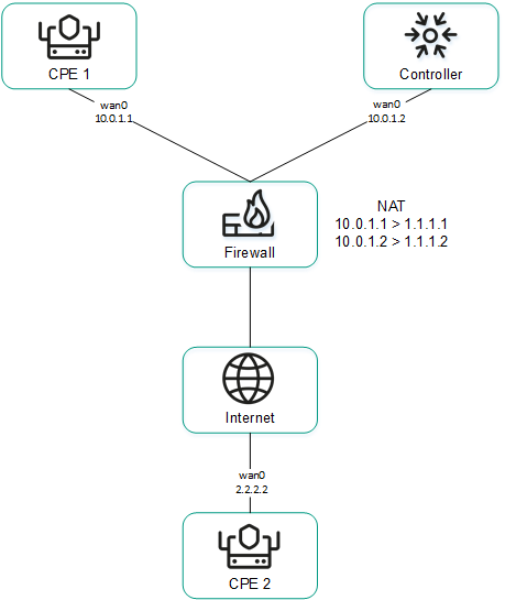
CPE 1 and the controller are behind NAT and are connected to CPE 2
Sending IP addresses of SD-WAN interfaces of the WAN type located in an isolated network to the controller
SD-WAN interfaces of the WAN type may be on an isolated network without the possibility of establishing a management session with the controller, but they can be used to establish links. In this case, the controller cannot obtain information about the IP addresses of isolated SD-WAN interfaces of the WAN type and use it to establish links between CPE devices.
In the figure below, CPE 1 and CPE 2 have two SD-WAN interface of the WAN type each, but they can establish a management session with the controller only through wan0 because wan1 is on an isolated network (MPLS) that does not have access to the controller. However, both wan1 interfaces can be used to establish links.
If the link used to interact with the controller fails for one of the CPE devices, all other links also cannot be used, even if they remain operational, because the Controller eliminates the device from the topology.
The IP addresses of isolated SD-WAN interfaces of the WAN type are sent to the controller through the orchestrator.
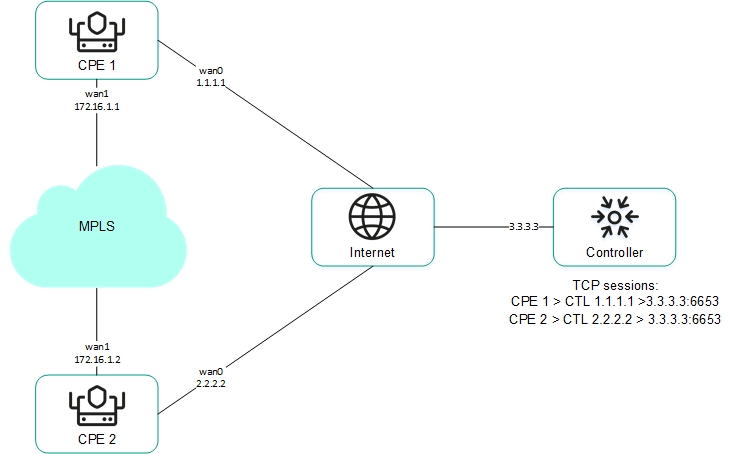
CPE 1 and CPE 2 are connected with each other through MPLS and with the controller through the Internet.
Page top