Contents
- Kaspersky SD-WAN Help
- About Kaspersky SD-WAN
- Architecture of the solution
- Deploying Kaspersky SD-WAN
- Redundancy of solution components
- About the installation archive
- About the attended, unattended, and partially attended action modes
- Preparing the administrator device
- Managing passwords
- Preparing the configuration file
- Replacing the graphics of the orchestrator web interface
- Replacement of a failed controller node
- Upgrading Kaspersky SD-WAN
- Removing Kaspersky SD-WAN
- Logging in and out of the orchestrator web interface
- Licensing of Kaspersky SD-WAN
- User interface of the solution
- Navigating to the orchestrator API
- Managing the Kaspersky SD-WAN infrastructure
- Managing domains
- Managing data centers
- Managing management subnets
- Managing controllers
- Managing a VIM
- Managing users and their access permissions
- Multitenancy
- Managing CPE devices
- About the interaction of the CPE device and the orchestrator
- About the interaction of the CPE device and the controller
- Default credentials of KESR CPE devices
- Scenario: Automatic registration (ZTP) of a CPE device
- Scenario: Deployment on the VMware virtualization platform and automatic registration (ZTP) of a vCPE device
- Scenario: Re-registering a CPE device
- Managing CPE templates
- Managing CPE devices
- Adding a CPE device
- Generating an URL with basic CPE device settings
- Manually registering a CPE device
- Unregistering a CPE device
- Specifying the address of a CPE device
- Enabling and disabling a CPE device
- Restarting a CPE device
- Shutting down a CPE device
- Connecting to the CPE device console
- Viewing the password of a CPE device
- Exporting orchestrator and controller connection settings and SD-WAN interfaces from a CPE device
- Exporting network interfaces from a CPE device
- Changing the DPID of a CPE device
- Deleting CPE devices
- Two-factor authentication of a CPE device
- Managing certificates
- Automatically deleting and disabling CPE devices
- Grouping CPE devices using tags
- Configuring logs on CPE devices
- Specifying NTP servers on CPE devices
- Managing modems
- Updating firmware
- Manually updating firmware on a CPE device
- Uploading firmware to the orchestrator web interface
- Scheduling firmware updates on selected CPE devices
- Scheduling firmware updates on CPE devices with specific tags
- Restoring firmware of a KESR-M1 CPE device
- Restoring firmware of a KESR-M2-5 CPE device
- Correspondence of CPE device models with firmware versions
- Deleting firmware
- Additional configuration of CPE devices using scripts
- Managing network interfaces
- Creating network interfaces
- Creating a network interface with automatic assignment of an IP address via DHCP
- Creating a network interface with a static IPv4 address
- Creating a network interface with a static IPv6 address
- Creating a network interface for connecting to an LTE network
- Creating a network interface for connecting to a PPPoE server
- Creating a network interface without an IP address
- Editing a network interface
- Disabling or enabling a network interface
- Canceling the application of network interface settings to a CPE device
- Deleting a network interface
- Creating network interfaces
- Configuring the connection of a CPE device to the orchestrator and controller
- Managing SD-WAN interfaces
- About sending information about SD-WAN interfaces of the WAN type to the controller
- Package fragmentation
- Traffic queues on SD-WAN interfaces
- Creating an SD-WAN interface of the WAN type
- Editing an SD-WAN interface
- Disabling or enabling an SD-WAN interface
- Deleting an SD-WAN interface of the WAN type
- Managing service interfaces
- Managing OpenFlow port groups
- Configuring a UNI for connecting CPE devices to network services
- Adding a static route
- Filtering routes and traffic packets
- Route exchange over BGP
- Route exchange over OSPF
- Using BFD to detect routing failures
- Ensuring high availability with VRRP
- Transmission of multicast traffic using PIM and IGMP protocols
- Managing virtual routing and forwarding (VRF) tables
- Monitoring traffic packet information using the NetFlow protocol
- Diagnosing a CPE device
- Running scheduled tasks on CPE devices
- IP address and subnet ranges for CPE devices
- Managing the firewall
- Managing network services and virtualization of network functions
- Managing network service templates
- Managing network services
- Scenario: Deploying a virtual network function
- Scenario: Deploying a physical network function
- Managing VNF and PNF packages
- Specifying a brief description of a shared network service
- Managing virtual network functions
- Selecting the flavour of a virtual network function
- Configuring external connection points of a virtual network function
- Basic settings of a virtual network function
- Hosting the virtual network function in a data center and on a uCPE device
- Stopping or starting a virtual network function or a VDU that is part of it
- Pausing or unpausing a virtual network function or a VDU that is part of it
- Suspending or unsuspending a virtual network function or a VDU that is part of it
- Soft rebooting a virtual network function or a VDU that is part of it
- Hard rebooting of a virtual network function or a VDU that is part of it
- Redeploying a virtual network function or a VDU that is part of it
- Auto-healing a virtual network function or a VDU that is part of it
- Managing VDU snapshots
- Managing physical network functions
- Configuring a P2P service
- Configuring a P2M service
- Configuring an M2M service
- Configuring a shared network (OS 2 SHARED)
- Configuring a virtual router (OS vRouter)
- Configuring a VLAN
- Configuring a VXLAN
- Configuring a flat network
- Configuring a UNI
- Monitoring solution components
- Specifying the Zabbix server
- Specifying the Zabbix proxy server
- Configuring CPE device monitoring
- Viewing monitoring results
- Viewing problems
- Viewing the status of the solution and its components
- Viewing logs
- Viewing and deleting service requests
- Sending CPE device notifications to users
- Selecting the Docker container log verbosity
- Monitoring CPE, VNF, and PNF devices using SNMP
- Link monitoring
- Building an SD-WAN network between CPE devices
- Quality of Service (QoS)
- Transmission of traffic between CPE devices and client devices using transport services
- Traffic packet duplication
- Scenario: Directing application traffic to a transport service
- Managing Point-to-Point (P2P) transport services
- Managing Point-to-Multipoint (P2M) transport services
- Managing Multipoint-to-Multipoint (M2M) transport services
- Managing L3 VPN transport services
- Managing IP multicast transport services
- Managing transport services in an SD-WAN instance template
- Managing transport services in a CPE template
- Traffic mirroring and forwarding between CPE devices
- Appendices
- Glossary
- Control plane
- Controller
- Customer Premise Equipment (CPE)
- Data plane
- Orchestrator
- Physical Network Function (PNF)
- PNF package
- Port security
- SD-WAN Gateway
- SD-WAN instance
- Software-Defined Networking (SDN)
- Software-Defined Wide Area Network (SD-WAN)
- Tenant
- Transport strategy
- Universal CPE (uCPE)
- Virtual Deployment Unit (VDU)
- Virtual Infrastructure Manager (VIM)
- Virtual Network Function Manager (VNFM)
- VNF Package
- Contacting Technical Support
- Information about third-party code
- Trademark notices
Kaspersky SD-WAN Help
 New features
What's new in each version of Kaspersky SD-WAN
 Hardware and software requirements
Review the hardware and software requirements
 Getting started
- Deploying Kaspersky SD-WAN
- Managing the corporate infrastructure
- Managing users and their access permissions
- Multitenancy
 Monitoring and reports
- Configuring logs on CPE devices
- Monitoring traffic packet information using the NetFlow protocol
- Diagnosing CPE devices
- Monitoring solution components
 Updating
Update Kaspersky SD-WAN from a previous version
 Additional features
 Appendices
Get information about Kaspersky SD-WAN from additional guides
About Kaspersky SD-WAN
Kaspersky SD-WAN is used to build Software-Defined Wide Area Networks (Software Defined WAN; SD-WAN). In such networks, routes with the lowest latency and the greatest bandwidth are determined automatically. Traffic is routed using the SDN (Software Defined Networking) technology.
The SDN technology separates the
from the and allows managing the network infrastructure using an and the API. Separating the control plane from the data plane makes it possible to virtualize network functions (Network Function Virtualization; NFV), wherein network functions such as firewalls, routers, and load balancers are deployed on standard equipment. Network function virtualization in the solution is compliant with the NFV MANO specification (NFV Management and Network Orchestration) standards of the European Telecommunications Standards Institute (ETSI).Building an SD-WAN network does not depend on transport technologies. You can also send traffic over multiple links based on application requirements regarding bandwidth and quality of service. The following underlay network types are supported:
- MPLS transport networks
- Broadband links for connecting to the Internet
- Leased communication lines
- Wireless connections including 3G, 4G, and LTE
- Satellite links
Kaspersky SD-WAN lets you do the following:
- Intelligent traffic management
- Automatic CPE device configuration
- Central management of solution components using the web interface
- Network monitoring
- Automatically responding to changes in QoS policies to meet requirements of applications
The figure below shows a diagram of an SD-WAN network built using the Kaspersky SD-WAN solution.
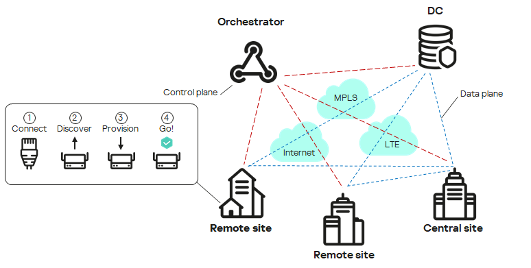
SD-WAN network diagram
Distribution kit
To learn more about purchasing the solution, please visit the Kaspersky website (https://www.kaspersky.com) or contact partner companies.
The distribution kit includes the following components:
- knaas-installer_<version> in the TAR.GZ format (hereinafter also referred to as the installation archive) for solution deployment.
- Docker containers for deploying Kaspersky SD-WAN components:
- knaas-ctl
- knaas-orc
- knaas-www
- knass-vnfm
- knaas-vnfm-proxy
- mockpnf
You must download the following containers from the common Docker repository:
- mariaDB
- mongo
- redis
- syslog-ng
- zabbix-proxy-mysql
- zabbix-server-mysql
- zabbix-web-nginx-mysql
- CPE device firmware.
- A file with the text of the End User License Agreement, which stipulates the terms and conditions that you must accept to use the solution.
- Kaspersky SD-WAN Online Help files that let you read documentation without an Internet connection.
The content of the distribution kit may differ depending on the region in which the solution is distributed.
Page top
Hardware and software requirements
Kaspersky SD-WAN has the following hardware and software requirements:
Hardware requirements depend on the number of CPE devices being managed (see the table below). If you need to connect more than 250 CPE devices, you need to deploy additional controllers. If you need to calculate hardware requirements for a specific deployment scheme more precisely, we recommend contacting Kaspersky Technical Support.
Component |
RAM, GB |
Virtual CPU |
Disk, GB |
IOPS |
50 CPE devices |
||||
Redis replica server |
1 |
2 |
100 |
1000 |
Redis Sentinel system |
1 |
2 |
||
MongoDB database |
2 |
2 |
||
Orchestrator |
4 |
4 |
||
Virtual Network Function Manager (VNFM) |
1 |
2 |
||
Proxy Virtual Network Function Manager (VNFM proxy) |
1 |
2 |
||
Frontend part of the solution |
1 |
2 |
||
Database of the Zabbix monitoring system |
1 |
2 |
500 |
1000 |
Zabbix server |
1 |
2 |
||
Frontend part of the Zabbix monitoring system |
1 |
2 |
||
Zabbix proxy server |
1 |
2 |
||
Syslog server |
1 |
1 |
No value |
No value |
Data storage system |
8 |
8 |
20 |
1000 |
Controller |
8 |
8 |
64 |
1000 |
100 CPE devices |
||||
Redis replica server |
1 |
2 |
100 |
1000 |
Redis Sentinel system |
1 |
2 |
||
MongoDB database |
4 |
4 |
||
Orchestrator |
4 |
4 |
||
Virtual Network Function Manager (VNFM) |
1 |
2 |
||
Proxy Virtual Network Function Manager (VNFM proxy) |
1 |
2 |
||
Frontend part of the solution |
2 |
2 |
||
Database of the Zabbix monitoring system |
1 |
4 |
1000 |
1000 |
Zabbix server |
1 |
2 |
||
Frontend part of the Zabbix monitoring system |
1 |
2 |
||
Zabbix proxy server |
1 |
2 |
||
Syslog server |
1 |
2 |
No value |
No value |
Data storage system |
8 |
8 |
20 |
1000 |
Controller |
8 |
8 |
64 |
1000 |
250 CPE devices |
||||
Redis replica server |
2 |
2 |
100 |
1000 |
Redis Sentinel system |
2 |
2 |
||
MongoDB database |
4 |
4 |
||
Orchestrator |
4 |
6 |
||
Virtual Network Function Manager (VNFM) |
2 |
2 |
||
Proxy Virtual Network Function Manager (VNFM proxy) |
2 |
2 |
||
Frontend part of the solution |
2 |
2 |
||
Database of the Zabbix monitoring system |
2 |
4 |
2500 |
1000 |
Zabbix server |
2 |
4 |
||
Frontend part of the Zabbix monitoring system |
2 |
2 |
||
Zabbix proxy server |
2 |
2 |
||
Syslog server |
2 |
2 |
No value |
No value |
Data storage system |
10 |
8 |
20 |
1000 |
Controller |
16 |
8 |
64 |
1000 |
500 CPE devices |
||||
Redis replica server |
2 |
2 |
100 |
1000 |
Redis Sentinel system |
2 |
2 |
||
MongoDB database |
4 |
6 |
||
Orchestrator |
6 |
6 |
||
Virtual Network Function Manager (VNFM) |
2 |
2 |
||
Proxy Virtual Network Function Manager (VNFM proxy) |
2 |
2 |
||
Frontend part of the solution |
2 |
2 |
||
Database of the Zabbix monitoring system |
2 |
4 |
5000 |
1000 |
Zabbix server |
2 |
4 |
||
Frontend part of the Zabbix monitoring system |
2 |
4 |
||
Zabbix proxy server |
2 |
4 |
||
Syslog server |
2 |
2 |
No value |
No value |
Data storage system |
10 |
8 |
20 |
1000 |
Controller |
32 |
8 |
128 |
1000 |
1000 CPE devices |
||||
Redis replica server |
2 |
4 |
100 |
1000 |
Redis Sentinel system |
2 |
2 |
||
MongoDB database |
6 |
6 |
||
Orchestrator |
8 |
6 |
||
Virtual Network Function Manager (VNFM) |
2 |
2 |
||
Proxy Virtual Network Function Manager (VNFM proxy) |
2 |
2 |
||
Frontend part of the solution |
2 |
2 |
||
Database of the Zabbix monitoring system |
2 |
6 |
1000 |
1000 |
Zabbix server |
2 |
6 |
||
Frontend part of the Zabbix monitoring system |
2 |
4 |
||
Zabbix proxy server |
2 |
4 |
||
Syslog server |
2 |
6 |
No value |
No value |
Data storage system |
12 |
10 |
20 |
1000 |
Controller |
64 |
8 |
256 |
1000 |
2000 CPE devices |
||||
Redis replica server |
4 |
4 |
200 |
2000 |
Redis Sentinel system |
4 |
2 |
||
MongoDB database |
8 |
6 |
||
Orchestrator |
10 |
6 |
||
Virtual Network Function Manager (VNFM) |
4 |
2 |
||
Proxy Virtual Network Function Manager (VNFM proxy) |
4 |
2 |
||
Frontend part of the solution |
4 |
4 |
||
Database of the Zabbix monitoring system |
4 |
6 |
2000 |
2000 |
Zabbix server |
4 |
6 |
||
Frontend part of the Zabbix monitoring system |
4 |
6 |
||
Zabbix proxy server |
4 |
6 |
||
Syslog server |
4 |
6 |
No value |
No value |
Data storage system |
16 |
12 |
20 |
1000 |
Controller |
128 |
8 |
512 |
1000 |
5000 CPE devices |
||||
Redis replica server |
6 |
4 |
500 |
5000 |
Redis Sentinel system |
6 |
2 |
||
MongoDB database |
10 |
6 |
||
Orchestrator |
12 |
6 |
||
Virtual Network Function Manager (VNFM) |
6 |
4 |
||
Proxy Virtual Network Function Manager (VNFM proxy) |
6 |
2 |
||
Frontend part of the solution |
8 |
4 |
||
Database of the Zabbix monitoring system |
6 |
8 |
5000 |
5000 |
Zabbix server |
6 |
8 |
||
Frontend part of the Zabbix monitoring system |
6 |
6 |
||
Zabbix proxy server |
6 |
6 |
||
Syslog server |
6 |
8 |
No value |
No value |
Data storage system |
32 |
16 |
50 |
1000 |
Controller |
320 |
8 |
1280 |
1000 |
10,000 CPE devices |
||||
Redis replica server |
8 |
4 |
1000 |
10,000 |
Redis Sentinel system |
8 |
2 |
||
MongoDB database |
12 |
8 |
||
Orchestrator |
16 |
8 |
||
Virtual Network Function Manager (VNFM) |
8 |
4 |
||
Proxy Virtual Network Function Manager (VNFM proxy) |
8 |
2 |
||
Frontend part of the solution |
8 |
4 |
||
Database of the Zabbix monitoring system |
32 |
8 |
10,000 |
10,000 |
Zabbix server |
16 |
8 |
||
Frontend part of the Zabbix monitoring system |
8 |
8 |
||
Zabbix proxy server |
8 |
8 |
||
Syslog server |
8 |
8 |
No value |
No value |
Data storage system |
64 |
32 |
100 |
1000 |
Controller |
640 |
8 |
2560 |
1000 |
Third-party solution requirements
The following third-party solutions are necessary to deploy the solution:
- The Zabbix monitoring system versions 5.0.26 or 6.0.0. For details, please refer to the official documentation of the Zabbix solution.
- The Docker cloud platform version 1.5 or later for deploying Docker containers of solution components. For details, please refer to the official documentation of the Docker cloud platform.
- The OpenStreetMap service for viewing the transport service topology overlaid on a map. If the infrastructure of your organization does not provide for an Internet connection, you can use offline maps. Offline maps take up additional disk space:
- The offline map (central-fed-district-latest.osm.pbf) takes up approximately 100 GB.
- Geocoding data takes up approximately 10 GB.
For detailed information, please refer to the official documentation of the OpenStreetMap service.
Operating system requirements
The following 64-bit operating systems are supported:
- Ubuntu 20.04 LTS or 22.04 LTS
- Astra Linux 1.7 (security level: "Orel").
- RED OS 8.
Requirements for deployment environments of central components of the solution
The following deployment environments are supported for central components of the solution:
- Bare-metal servers:
- CPU Intel Xeon E5-2600 v2 or later or an equivalent CPU.
- IOPS 3000 or later.
- VMWare virtualization environment:
- Version 7.0 or later.
- The openvm-tools agent must be installed.
- IOPS 3000 or later.
- KVM virtualization environment:
Only the original KVM virtualization environment without additional orchestration tools is supported.
- Kernel version 5.15 or later.
- qemu-guest-agent must be installed.
- The CPU must be in host mode.
- IOPS 3000 or later.
Requirements for links between nodes of solution components
When deploying Kaspersky SD-WAN, you can deploy multiple nodes of solution components. The following requirements apply to links between nodes of solution components:
- Requirements for links between controller nodes:
- Bandwidth: 1 Gbps
- RTT (Round Trip Time): 200 ms
- Packet loss: 0%
- Requirements for links between MongoDB database nodes:
- Bandwidth: 1 Gbps
- RTT: 50 ms
- Packet loss: 0%
- Requirements for links between Redis database nodes:
- Bandwidth: 1 Mbps
- RTT: 50 ms
- Packet loss: 0%
Browser requirements
The following browsers are supported for managing the orchestrator web interface:
- Google Chrome 100 or later
- Firefox 100 or later
- Microsoft Edge 100 or later
- Opera 90 or later
- Safari 15 or later
Requirements for the data storage system
We recommend using your own data storage system for fault tolerance. The following requirements apply to the data storage system:
- Support for simultaneous read and write from multiple hosts.
- The size of the data storage system depends on the size of the files being stored, but at least 40 GB of available protected space that supports further expansion.
- The bandwidth of the link between the storage system and the orchestrator must be at least 1 Gbps; 10-Gigabit Ethernet or 8-Gigabit FC (Fiber Channel) is recommended.
- At least 250 IOPS, at least 400 is recommended.
- The following types of data storage systems are supported:
- NFS
- iSCSI
- FC
- CephFS
- The data storage system must be mounted.
- Must stay available if the host restarts.
Administrator device requirements
The administrator device for deploying the solution must satisfy the following requirements:
- Operating system:
- Ubuntu 20.04 LTS or 22.04 LTS
- RED OS 8.
The operating system must support internet access or contain a mounted disk image.
- 4 virtual CPU cores.
- 8 GB of RAM.
- 32 GB of free disk space.
- The name and password of the root account must be the same on the administrator device and the virtual machines on which you want to deploy solution components.
CPE device requirements
The following CPE device models are supported:
- KESR-M1-R-5G-2L-W
- KESR-M2-K-5G-1L-W
- KESR-M2-K-5G-1S
- KESR-M3-K-4G-4S
- KESR-M4-K-2X-1CPU
- KESR-M4-K-8G-4X-1CPU
- KESR-M5-K-8G-4X-2CPU
- KESR-M5-K-8X-2CPU
CPE devices of the KESR model are based on x86 (Intel 80x86) and MIPS (Microprocessor without Interlocked Pipeline Stages) processor architectures.
Kaspersky experts carried out tests to confirm the functionality of CPE devices when providing the L3 VPN service (see the table below). DPI (Deep Packet Inspection) was not used on the tested devices, and traffic encryption was disabled.
Model |
Packet size (bytes) |
Bandwidth (Mbps) |
KESR-M1 |
IMIX (417) |
30 |
Large (1300) |
115 |
|
KESR-M2 |
IMIX (417) |
165 |
Large (1300) |
241 |
|
KESR-M3 |
IMIX (417) |
805 |
Large (1300) |
1150 |
|
KESR-M4 |
IMIX (417) |
1430 |
Large (1300) |
2870 |
For detailed information about the characteristics of CPE devices, please refer to the official page of the solution.
You can deploy uCPE devices on servers with x86 (Intel 80x86) or ARM64 processor architecture.
You can use the vKESR-M1 model as a vCPE device. The following virtualization environments are supported for vCPE devices:
- VMware 7.0 or later
- KVM with kernel version 5.15 or later
Only the original KVM virtualization environment without additional orchestration tools is supported.
vCPE devices of the vKESR-M1 model have the following specifications:
- CPU: 2x vCPU. We recommend using the Intel(R) Xeon(R) Gold 5318Y CPU.
- Virtual RAM: 512 MB.
- HDD: 1024 MB.
Ensuring security
Security in Kaspersky SD-WAN is ensured in the data plane, control plane, and orchestration plane. The security level of the solution as a whole is determined by the security level of each of these planes, as well as the security of their interaction. The following processes take place in each plane:
- User authentication and authorization
- Use of secure management protocols
- Encryption of control traffic
- Secure connection of CPE devices
Secure management protocols
We recommend using HTTPS when communicating with the SD-WAN network through the orchestrator web interface or API. You can upload your own certificates to the web interface or use automatically generated self-signed certificates. The solution uses several protocols to transmit control traffic to components (see the table below).
Interacting components |
Protocol |
Additional security measures |
|---|---|---|
Orchestrator and SD-WAN controller |
gRPC |
TLS is used for authentication and traffic encryption between the client and server. |
Orchestrator and CPE device |
HTTPS |
Certificate verification and a token are used for authentication and traffic encryption between the orchestrator and the CPE device. |
SD-WAN controller and CPE device |
OpenFlow 1.3.4 |
TLS is used for authentication and traffic encryption between the SD-WAN controller and the CPE device. |
Secure connection of CPE devices
The solution uses the following mechanisms for secure connection of CPE devices:
- Discovery of CPE device by DPID.
- Deferred registration. You can select the state of the CPE device after successful registration: Enabled or Disabled. A disabled CPE device must be enabled after making sure it is installed at the location.
- Two-factor authentication.
Using virtual network functions
You can provide an additional layer of security with virtual network functions deployed in the data center and/or on
. For example, traffic can be relayed from a CPE device to a virtual network function that acts as a firewall or proxy server. Virtual network functions can perform the following SD-WAN protection functions:- Next-Generation Firewall (NGFW)
- Protection from DDoS (Distributed Denial of Service) attacks
- Intrusion Detection System (IDS) and Intrusion Prevention System (IPS)
- Anti-Virus
- Anti-Spam
- Content Filtering and URL filtering system
- DLP (Data Loss Prevention) system for preventing confidential information leaks
- Secure Web Proxy
What's new
Kaspersky SD-WAN has the following new and improved functionality:
- Centralized firewall management is supported with firewall template and DPI support. Now you can disable or enable DPI when specifying basic firewall settings and specify DPI marks to apply firewall rules to application traffic packets.
- Now you can create DNAT and SNAT rules for firewall management if you want to use the Source Network Address Translation (SNAT), Destination Network Address Translation (DNAT), and Port Address Translation (PAT) mechanisms. You can centrally manage these mechanisms using firewall templates.
- You can use up to 100 virtual routing and forwarding tables (VRF) on CPE devices. You can put BGP routes into one of the virtual routing and forwarding tables.
- Now you can install certificate chains on CPE devices
- Now you can monitor traffic packet information using the NetFlow protocol versions 1, 5, and 9. You can centrally manage the protocol using NetFlow templates.
- Information about the following events is now sent to the Syslog server that you can specify:
- A user logging in or out of the orchestrator web interface.
- A user entering the password incorrectly when logging in to the orchestrator web interface.
- A user conducting a brute-force attack.
- An attempt to log in to the orchestrator web interface using a non-existent account.
- Two-factor authentication of users is now supported using the Time-based-one-time password (TOTP) algorithm.
- Support for upgrading Kaspersky SD-WAN from version 2.1.3 to 2.2.0. If you are using a version lower than 2.1.3, you must first upgrade the solution to version 2.1.3, and then to 2.2.0. You must first upgrade the central components of the solution, and then the CPE devices.
- The installation archive for quick deployment of Kaspersky SD-WAN is now available. The installation archive lets you modify elements of the orchestrator web interface, such as the displayed logo of your organization.
- Sending notifications about events and problems on CPE devices to user emails is now supported.
- Now you can diagnose CPE devices using the following utilities:
- Version 6.0.0 of the Zabbix monitoring system is supported.
- The OVF template for vCPE devices is supported. You can use an OVF template to deploy a vCPE device on the VMware virtualization platform and automatically register it.
- Optimized performance of the Controller and CPE devices.
- Optimized recovery of a failed Controller node.
- Now you can create IP address and subnet ranges for CPE devices (IPAM). You can use these ranges to centrally assign IPv4 addresses to network interfaces of CPE devices. You can also use IP address ranges to centrally assign IPv4 addresses to CPE router IDs.
- CPE device names are now displayed in Zabbix monitoring system.
- Now you can place CPE, VNF, and PNF device hosts into automatically created groups on the Zabbix server. Groups correspond to tenants to which VNFs, PNFs, and CPE devices belong.
- The RED OS 8 operating system is supported for central components of the solution.
- Users with the tenant role can now change the password.
- Assigned IPv4 addresses can now be displayed in the table of network interfaces of a CPE device.
- Now you can create network interfaces for connecting to a PPPoE server.
- CPE devices can now relay multicast traffic using the PIM and IGMP protocols.
Architecture of the solution
Kaspersky SD-WAN includes the following main components:
- The orchestrator controls the solution infrastructure, functions as an NFV orchestrator (NFVO), and manages network services and distributed VNFMs. You can manage the orchestrator via the web interface or REST API when using external northbound systems.
- The Controller centrally manages the overlay network:
- Builds the network topology.
- Creates transport services.
- Manages CPE devices using the OpenFlow protocol.
- Balances traffic between links.
- Monitors link and automatically switches traffic to a backup link if the primary link fails.
To deploy the Controller, you need to deploy the physical network function of the Controller, which is contained in the installation archive. The Controller is managed by the orchestrator.
- CPE devices are installed at remote locations to relay traffic and form an SDN fabric in the form of an overlay network. You can assign the SD-WAN Gateway role or the standard CPE device role o the CPE device. SD-WAN Gateways establish links with all standard CPE devices and other SD-WAN Gateways. Standard CPE devices establish connections only with SD-WAN Gateways. By default, all CPE devices have assigned the standard CPE device role.
If you want a link to be established between two standard CPEs, you need to assign the same topology tag to these standard CPEs. You can also make a standard CPE device a transit device to allow other CPE devices to make links through that CPE device.
- The VNFM (Virtual Network Functiion Manager) manages the lifecycle of virtual network functions using SSH, Ansible playbooks, scripts, and Cloud-init attributes.
If virtual network functions are used, the architecture includes a Virtual Infrastructure Manager (VIM) that manages compute, network, and storage resources within the NFV infrastructure. A VIM connects VNFs using virtual links, subnets, and ports. The OpenStack cloud platform is used as the VIM.
Kaspersky SD-WAN has a distributed microservice architecture based on Docker containers (see the figure below). A Controller can include one, three, or five nodes. Controller nodes are deployed on separate virtual machines, which you can run on different physical servers for fault tolerance. When deploying the solution, you can specify virtual machines on which you want to deploy Controller nodes.

Architecture of Kaspersky SD-WAN
Page top
Deploying Kaspersky SD-WAN
You can deploy Kaspersky SD-WAN using the knaas-installer_<version information> installation archive that is part of the distribution kit.
Before following this procedure, you must prepare a solution deployment scenario. If you have any problems with preparing a deployment scenario, we recommend contacting Kaspersky Technical Support.
A solution deployment scenario consists of the following steps:
- Preparing the administrator device
Prepare the administrator device for solution deployment. You can use a local or remote virtual machine, or a personal computer as the administrator device. When deploying a Kaspersky SD-WAN testbed in accordance with the all-in-one deployment scenario, you must use a virtual machine as the administrator device.
- Ensuring network connectivity between the administrator device and solution components
Ensure network connectivity between the administrator device and the virtual machines or physical servers on which you want to deploy Kaspersky SD-WAN components. If you plan to deploy multiple nodes of solution components, make sure that the links between virtual machines or physical servers satisfy the hardware and software requirements.
- Manually generating passwords
If necessary, manually generate passwords to ensure the security of Kaspersky SD-WAN components and their SSL certificates.
- Preparing the configuration file
Prepare the configuration file in accordance with the chosen deployment scenario. You can use example configuration files for typical deployment scenarios in the /inventory/external/pnf and /inventory/external/vnf directories of the installation archive.
- Replacing the graphics of the orchestrator web interface
If necessary, replace the graphics of the orchestrator web interface. For example, you can replace the image that is displayed in the background when an error occurs while logging into the orchestrator web interface.
- Deploying Kaspersky SD-WAN
Do the following on the administrator device:
- Accept the End User License Agreement by running the following command:
export KNAAS_EULA_AGREED="true" - Go to the directory with the extracted installation archive.
- If you want to deploy Kaspersky SD-WAN in attended mode, do one of the following:
- If you have generated passwords manually, run the command:
ansible-playbook -i inventory/generic -e "@<path to configuration file>" -e "@inventory/external/images.yml" -K --ask-vault-pass knaas/knaas-install.ymlWhen running the command, enter the root account password and the generated master password.
- If you have not generated passwords manually, run the command:
ansible-playbook -i inventory/generic -e "@<path to configuration file>" -e "@inventory/external/images.yml" -K knaas/knaas-install.yml
- If you have generated passwords manually, run the command:
- If you want to deploy Kaspersky SD-WAN in unattended mode, do one of the following:
We only recommend using this mode in a trusted environment because it makes intercepting your passwords easy for a malicious actor.
- If you have generated passwords manually, run the command:
ansible-playbook -i inventory/generic -e "@<path to configuration file>" -e "@inventory/external/images.yml" -e "ansible_become_password=yourSudoPassword" --vault-password-file ./passwords/vault_password.txt knaas/knaas-install.yml - If you have not generated passwords manually, run the command:
ansible-playbook -i inventory/generic -e "@<path to configuration file>" -e "@inventory/external/images.yml" -e "ansible_become_password=yourSudoPassword" knaas/knaas-install.yml
- If you have generated passwords manually, run the command:
- Accept the End User License Agreement by running the following command:
The Kaspersky SD-WAN components are deployed on the virtual machines or physical servers that you specified in the configuration file. A successful deployment message is displayed in the console of the administrator device.
If a network connectivity issue occurs with one of the virtual machines or physical servers during the deployment of solution components, an error message is displayed in the administrator device console, and the solution is not deployed. In that case, you need to restore network connectivity, clean up the virtual machines or physical servers, and then run the deployment command again.
Redundancy of solution components
About redundancy schemes for solution components
Kaspersky SD-WAN supports two deployment scenarios for solution components:
- In the N+1 deployment scenario, you deploy two nodes of the solution component. If one node fails, the second node provides the functionality of the solution component.
- In the 2N+1 deployment scenario, you deploy multiple nodes of the solution component. One node is the primary node and the rest are secondary nodes. If the primary node fails, a randomly chosen secondary node takes its place. This redundancy scheme allows solution components to remain operational even when multiple failures occur in a row.
The table below lists the solution components and the deployment scenarios that are applicable to them.
Solution component |
Redundancy scheme |
Database of the Zabbix monitoring system |
2N+1 |
Zabbix server |
N+1 |
Frontend part of the Zabbix monitoring system |
N+1 |
Zabbix proxy server |
N+1 |
MongoDB database |
2N+1 |
Redis database:
|
2N+1 |
Controller |
2N+1 |
Frontend part of the solution |
N+1 |
Orchestrator |
N+1 |
Virtual Network Function Manager |
N+1 |
Virtual Network Function Manager proxy |
N+1 |
You can specify the number of nodes you want to deploy for each solution component in the configuration file.
When you configure the deployment settings for the MongoDB database or the controller node in accordance with the 2N+1 deployment scenario, the last node you specify becomes the arbiter node. The arbiter node is linked to other nodes and is used to choose the primary node. A node that has lost contact with the arbiter node enters standby mode. One of the nodes that have retained contact with the arbiter node stays or becomes the primary node. An arbiter node cannot become a primary node and does not store data.
Failure scenarios of solution component nodes
The figure below shows a diagram of Kaspersky SD-WAN deployed on three virtual machines in a data center. The diagram uses the following symbols:
- 'www' is the frontend part of the solution
- 'orc' is the orchestrator
- 'mongo' is the MongoDB database
- 'redis-m' is a Redis replica server
- 'redis-s' is a Redis Sentinel system
- 'vnfm-proxy' is a virtual network functions manager proxy
- 'vnfm' is a Virtual Network Function Manager
- 'ctl' is the controller and its database
- 'zabbix-www' is the frontend part of the Zabbix monitoring system
- 'zabbix-proxy' is the Zabbix proxy server
- 'zabbix-srv' is the Zabbix server
- 'zabbix-db' is the database of the Zabbix monitoring system
- 'syslog' is the Syslog server
Users and CPE devices gain access to the web interface of the orchestrator and the web interface of the Zabbix monitoring system using a virtual IP address. The virtual IP address is assigned to virtual machine 1.
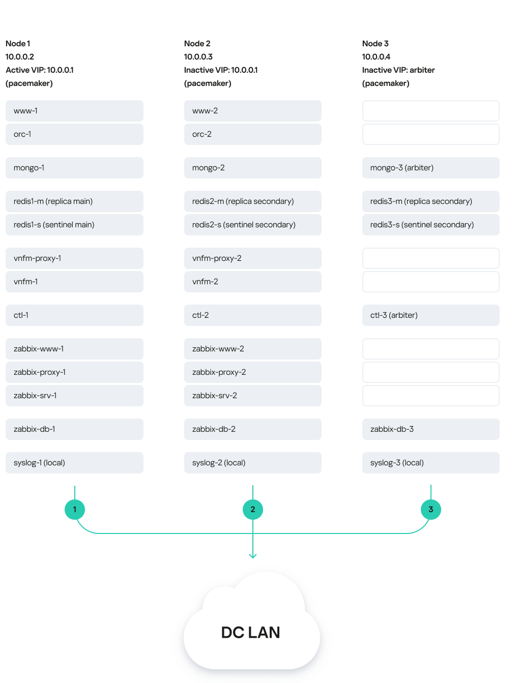
Solution deployed on three virtual machines
In this deployment scenario, the following failure modes are possible:
- Failure of virtual machine 1 or its link.
- Failure of virtual machine 2 or 3, or its link.
- Simultaneous failure of virtual machines 1 and 3 or 2 and 3, or their links.
- Simultaneous failure of virtual machines 1 and 2
About the installation archive
The knaas-installer_<version information> installation archive has the TAR format and is used for solution deployment. You can download the installation archive from the root directory of the distribution kit. The installation archive has the following structure:
We do not recommend editing system files because this may cause errors when deploying the solution.
- ansible.cfg file is a system file with Ansible settings.
- CHANGELOG.md is the file change log in YAML format.
- /docs contains the installation archive documentation.
- /images contains images of the solution components.
- /inventory:
- /external:
- /pnf contains example configuration files for typical solution deployment scenarios with the controller as a physical network function.
- /vnf contains example configuration files for typical solution deployment scenarios with the controller as a virtual network function.
- /external:
- /generic contains common system files.
- /knaas contains system files with playbooks for deploying the solution.
- /oem contains default graphics of the orchestrator web interface.
- /pnfs contains physical network functions for deployment of one, three, or five controller nodes.
- README.md contains instructions for deploying the solution using the installation archive.
- requirements.txt is a system file with Python requirements.
About the attended, unattended, and partially attended action modes
When you perform actions on the administrator device when deploying Kaspersky SD-WAN, you may need to enter the root password as well as the master password. How the passwords are entered depends on the mode in which you are performing the action. The following action modes are supported:
- In the attended mode, an employee must take part in the action. To perform an action, you must manually enter the root password and the master password. This is the safest mode that avoids saving any passwords on the administrator device.
- In the unattended mode, the action is performed without involving an employee. To perform an action, the root password and the master password are entered automatically. In this mode, you can run automated tests.
We only recommend using this mode in a trusted environment because it makes intercepting your passwords easy for a malicious actor.
- In the partially attended mode, the action is performed with partial involvement of an employee. When performing an action, you must enter the root password, but the master password is entered automatically.
Preparing the administrator device
You can use a local or remote virtual machine, or a personal computer as the administrator device. When deploying a Kaspersky SD-WAN testbed in accordance with the all-in-one deployment scenario, you must use a virtual machine as the administrator device.
If you experience any problems while preparing the administrator device, we recommend contacting Kaspersky Technical Support.
To prepare the administrator device:
- Make sure the administrator device satisfies the hardware and software requirements.
- Make sure that the same root account is used on the administrator device and the virtual machines or physical servers on which you want to deploy Kaspersky SD-WAN components. After deploying the solution, you can use a different root account on the virtual machines or physical servers.
- Download the knaas-installer_<version information> installation archive from the root directory of the distribution kit and extract the installation archive on the administrator device.
- Go to the directory with the extracted installation archive and prepare the administrator device:
- Make sure the pip package management tool is installed by running the command:
python3 -m pip -V - If the pip package management tool is not present, do one of the following:
- If the administrator device is running Ubuntu:
apt-get install python3-pip - If the administrator device is running RED OS 8:
yum install python3-pip
- If the administrator device is running Ubuntu:
- Install the Ansible tool and its dependencies:
python 3 -m pip install -U --user -r requirements.txt - Update the PATH variable:
echo 'export PATH=$PATH:$HOME/.local/bin' >> ~/.bashrcsource ~/.bashrc
- Verify that the Ansible tool is ready for use:
ansible --version - Install the operating system packages for Kaspersky SD-WAN deployment on the administrator device:
ansible-playbook -K knaas/utilities/toolserver_prepare/bootstrap.ymlEnter the root password when running the command.
You only need to complete this step when initially deploying the solution.
- Make sure the pip package management tool is installed by running the command:
- Make sure the administrator device is ready for use:
- Restart the administrator device.
- Go to the extracted installation archive and start the automatic check of the administrator device:
ansible-playbook knaas/utilities/pre-flight.yml
- If you want to deploy Kaspersky SD-WAN on multiple virtual machines or physical servers:
- Make sure SSH keys have been generated on the administrator device. If the SSH keys do not exist, generate them.
- Place the SSH keys on virtual machines or physical servers:
ssh-copy-id user@<IP address of the virtual machine or physical server>
If you are deploying a Kaspersky SD-WAN testbed in accordance with the all-in-one deployment scenario, skip this step.
The administrator device is prepared for Kaspersky SD-WAN deployment.
Page top
Managing passwords
Passwords help ensure the security of deployed Kaspersky SD-WAN components. You can manually generate the passwords. If you do not manually generate the passwords, they are generated automatically when you deploy the solution.
Passwords are contained in the following files:
- keystore.yml contains passwords of Kaspersky SD-WAN components and their SSL certificates.
- vault_password.txt contains the master password.
We recommend storing password files in a protected directory because they can be used to gain access to the deployed solution.
After deployment, the generated passwords are automatically placed in the Docker containers of Kaspersky SD-WAN components. Solution components exchange passwords when interacting with each other.
Manually generating passwords
To manually generate the passwords:
- Create the /passwords directory on the administrator device. Specify the path to the created directory in the
externalsection of the configuration file using thevault_password_dirnamesetting. - Create a keystore.yml file and in that file, specify the passwords using the following settings:
ZABBIX_DB_SECRETis the root password of the Zabbix monitoring system database.MONGO_ADMIN_SECRETis the administrator password of the MongoDB database.MONGO_USER_SECRETis the user password of the MongoDB database. This password is used by the orchestrator.CTL_CERT_SECRETis the password of the controller SSL certificate.ORC_CERT_SECRETis the password of the orchestrator SSL certificate.ORC_ENC_SECRETis the password for encrypting confidential data in the MongoDB database. Minimum length: 32 characters.VNFM_CERT_SECRETis the password of the VNFM SSL certificate.
For all passwords except
ORC_ENC_SECRET, we recommend specifying at least 16 characters. - Create the vault_password.txt file and in that file, specify the master password.
- Encrypt the keystore.yml file:
- If you want to encrypt the keystore.yml file in attended mode:
ansible-vault encrypt --ask-vault-pass keystore.yml - If you want to encrypt the keystore.yml file in unattended mode:
ansible-vault encrypt --vault-password-file vault_password.txt keystore.yml
- If you want to encrypt the keystore.yml file in attended mode:
The passwords are generated and encrypted.
Changing passwords
To change the passwords:
- Decrypt the keystore.yml file:
- If you want to decrypt the keystore.yml file in attended mode:
ansible-vault decrypt --vault-password-file vault_password.txt keystore.yml - If you want to decrypt the keystore.yml file in unattended mode:
ansible-vault encrypt --ask-vault-pass keystore.yml
- If you want to decrypt the keystore.yml file in attended mode:
- Change the following passwords in the keystore.yml file:
ZABBIX_DB_SECRETis the root password of the Zabbix monitoring system database.MONGO_ADMIN_SECRETis the administrator password of the MongoDB database.MONGO_USER_SECRETis the user password of the MongoDB database. This password is used by the orchestrator.CTL_CERT_SECRETis the password of the controller SSL certificate.ORC_CERT_SECRETis the password of the orchestrator SSL certificate.ORC_ENC_SECRETis the password for encrypting confidential data in the MongoDB database. Minimum length: 32 characters.VNFM_CERT_SECRETis the password of the VNFM SSL certificate.
For all passwords except
ORC_ENC_SECRET, we recommend specifying at least 16 characters. - Encrypt the keystore.yml file:
- If you want to encrypt the keystore.yml file in attended mode:
ansible-vault encrypt --ask-vault-pass keystore.yml - If you want to encrypt the keystore.yml file in unattended mode:
ansible-vault encrypt --vault-password-file vault_password.txt keystore.yml
- If you want to encrypt the keystore.yml file in attended mode:
The passwords are changed and encrypted.
Page top
Preparing the configuration file
Specify the Kaspersky SD-WAN deployment settings in the YAML configuration file on the administrator device. The path to the configuration file must be specified when deploying the solution. You can use example configuration files for typical deployment scenarios in the inventory/external/pnf and inventory/external/vnf directories of the installation archive.
The configuration file consists of two main sections:
- The
nodessection specifies virtual machines or physical servers for deploying Kaspersky SD-WAN components. When deploying the solution to virtual machines or physical servers, iptables rules for interaction between solution components are automatically generated. - The
externalsection specifies Kaspersky SD-WAN deployment settings.
We do not recommend changing the default settings.
The nodes section has the following structure:
Section/setting |
Description |
||
|---|---|---|---|
|
Deployment settings of virtual machine or physical server. |
||
|
|
IP address of the virtual machine or physical server. Enter a value in the
|
|
|
Virtual IP address of the virtual machine or physical server. Enter a value in the
This setting must be specified for all virtual machines or physical servers on which you plan to use virtual IP addresses. |
||
|
Settings for connecting Docker containers of Kaspersky SD-WAN components to the local virtual network of the virtual machine or physical server. |
||
|
|
The first three octets of the local virtual network IP address. Default value:
You can change the first three octets of the default IP address if they overlap with your address space. |
|
|
Operating mode of the local virtual network. Possible values:
|
||
|
Name of the virtual machine or physical server interface for connecting Docker containers over the L2 network, for example:
This parameter must be specified if for |
||
|
VLAN tag of the L2 network. Enter a value in the range of 1 to 4095. If you do not want to use a VLAN tag, enter This parameter must be specified if for |
||
|
Settings for connecting Docker containers of Kaspersky SD-WAN components to the management virtual network or physical server of the virtual machine. |
||
|
|
The first three octets of the management virtual network IP address. Default value:
You can change the first three octets of the default IP address if they overlap with your address space. |
|
|
Operating mode of the management virtual network. Possible values:
|
||
|
Name of the virtual machine or physical server interface for connecting Docker containers over the L2 network, for example:
This parameter must be specified if for |
||
|
VLAN tag of the L2 network. Enter a value in the range of 1 to 4095. If you do not want to use a VLAN tag, enter This parameter must be specified if for |
||
The external section has the following structure:
Section/setting |
Description |
|||
|
Path to the /passwords directory on the administrator device with manually generated passwords. If you do not generate passwords manually, they are automatically generated during solution deployment and placed in the /passwords directory of the extracted installation archive on the administrator device. |
|||
|
Name of the user account on the administrator device and on virtual machines or physical servers for running playbooks during solution deployment. |
|||
|
Settings of SSL certificates of Kaspersky SD-WAN components. |
|||
|
|
Information that is added to SSL certificates. |
||
|
|
IP addresses that are added to SSL certificates. Specify a list of values in the
|
||
|
Domain names that are added to SSL certificates. Specify a list of values, for example:
|
|||
|
Path to the directory on the administrator device that contains manually generated SSL certificates. If you do not generate SSL certificates manually, they are automatically generated during solution deployment and placed in the /ssl directory of the extracted installation archive on the administrator device. |
|||
|
Path to the directory on the virtual machines or physical servers that contains manually generated SSL certificates. If you do not generate SSL certificates manually, they are automatically generated during solution deployment and placed in the /ssl directory on virtual machines or physical servers. |
|||
|
Syslog server settings. |
|||
|
|
Amount of RAM in megabytes for Docker containers of the Syslog server. |
||
|
Amount of RAM in gigabytes for the Syslog server logs. |
|||
|
Deploying a Syslog server on virtual machines or physical servers. Possible values:
|
|||
|
Settings of the Zabbix monitoring system. For details, please refer to the official documentation of the Zabbix solution. |
|||
|
|
Web address of the Syslog server to which Docker containers of the Zabbix monitoring system send logs. Enter a value in the
You can specify Syslog server settings in the |
||
|
Amount of RAM in megabytes for Docker containers of the Zabbix monitoring system database. |
|||
|
Amount of RAM in megabytes for Docker containers of the Zabbix server. |
|||
|
Amount of RAM in megabytes for Docker containers of the Zabbix monitoring system front end. |
|||
|
Amount of RAM in megabytes for Docker containers of the Zabbix proxy server. |
|||
|
Amount of RAM in gigabytes for the Zabbix monitoring system cache. Enter a value in the
|
|||
|
Deployment settings of Zabbix monitoring system nodes. You can deploy one Zabbix monitoring system node without high availability or three nodes with high availability. |
|||
|
|
IP address of the virtual machine or physical server from the
|
||
|
Deployment settings of the Zabbix monitoring system database. |
|||
|
|
Host name of the Zabbix monitoring system database. Default value: |
||
|
Deployment of the database of the Zabbix monitoring system on a virtual machine or physical server. Possible values:
|
|||
|
Deployment settings of the Zabbix server. When deploying three nodes of the Zabbix monitoring system, you only need to specify these settings for two of the nodes. |
|||
|
|
Host name of the Zabbix server. Default value: |
||
|
Deploying the Zabbix server on a virtual machine or physical server. Possible values:
|
|||
|
Deployment settings of the frontend part of the Zabbix monitoring system. When deploying three nodes of the Zabbix monitoring system, you only need to specify these settings for two of the nodes. |
|||
|
|
Host name of the frontend part of the Zabbix monitoring system. Default value: |
||
|
Deployment of the frontend part of the Zabbix monitoring system on a virtual machine or physical server. Possible values:
|
|||
|
Deployment settings of the Zabbix proxy server. When deploying three nodes of the Zabbix monitoring system, you only need to specify these settings for two of the nodes. |
|||
|
|
Host name of the Zabbix proxy server. Default value: |
||
|
Deploying the Zabbix proxy server on a virtual machine or physical server. Possible values:
|
|||
|
MongoDB database settings. For details, please refer to the official documentation of the MongoDB database. |
|||
|
|
Web address of the Syslog server to which Docker containers of the MongoDB database send logs. Enter a value in the
You can specify Syslog server settings in the |
||
|
Amount of RAM in megabytes for Docker containers of the MongoDB database. |
|||
|
Deployment settings of MongoDB database nodes. You can deploy one MongoDB database node without high availability or three nodes with high availability. If you deploy three MongoDB database nodes, the last node becomes the arbiter node. |
|||
|
|
Host name of the MongoDB database. Default value: |
||
|
Deploying the MongoDB database on a virtual machine or physical server. Possible values:
|
|||
|
IP address of the virtual machine or physical server from the
|
|||
|
Redis database settings. For details, please refer to the official documentation of the Redis database. |
|||
|
|
Web address of the Syslog server to which Docker containers of the Redis database send logs. Enter a value in the
You can specify Syslog server settings in the |
||
|
Amount of RAM in megabytes for Docker containers of the Redis database. |
|||
|
Deployment settings for nodes of the Redis replica server. You can deploy one Redis replica server node without high availability or three nodes with high availability. |
|||
|
|
Host name of the Redis replica server. Default value: |
||
|
Deploying the Redis replica server on a virtual machine or physical server. Possible values:
|
|||
|
IP address of the virtual machine or physical server from the
|
|||
|
Deployment settings of Redis Sentinel system nodes. If you are deploying three Redis replica server nodes with high availability, you also need to deploy three nodes of the Redis Sentinel system. |
|||
|
|
Host name of the Redis Sentinel system. Default value: |
||
|
Deploying the Redis Sentinel system on a virtual machine or physical server. Possible values:
|
|||
|
IP address of the virtual machine or physical server from the
|
|||
|
Deployment settings of the controller. To deploy an SD-WAN instance for a tenant, you need to deploy the controller as a physical network function. |
|||
|
|
Settings for tenants for which you are deploying SD-WAN instances. |
||
|
Name of the tenant. |
|||
|
|
Creating a tenant and deploying the controller on a virtual machine or physical server. Possible values:
|
||
|
The first three octets of the IP address of the controller's virtual network. Enter a value in the
When deploying a Kaspersky SD-WAN testbed in accordance with the all-in-one deployment scenario, the value of this setting may be the same as the value of the |
|||
|
The first three octets of the IP address of the controller's management virtual network. Enter a value in the
|
|||
|
Deployment settings of the controller. You can deploy one controller node without high availability, or alternatively, three or five nodes with high availability. If you deploy three or five controller nodes, the last node becomes the arbiter node. |
|||
|
Host name of the controller node. Default value: |
|||
|
|
IP address of the virtual machine or physical server from the
|
||
|
Amount of RAM in megabytes for Docker containers of the controller. |
|||
|
RAM settings of the Java virtual machine. |
|||
|
|
The minimum amount of heap memory that the Java VM can allocate to the controller. Enter a value in one of the following formats:
We recommend specifying a value half as large as the |
||
|
The maximum amount of heap memory that the Java VM can allocate to the controller. Enter a value in one of the following formats:
We recommend specifying a value half as large as the |
|||
|
The maximum amount of direct memory that the Java VM can allocate to the controller. Enter a value in one of the following formats:
We recommend specifying a value half as large as the |
|||
|
Web address of the Syslog server to which Docker containers of the controller send logs. Enter a value in the
You can specify Syslog server settings in the |
|||
|
Settings of the frontend part of the solution. |
|||
|
|
Web address of the Syslog server to which Docker containers of the frontend part of the solution send logs. Enter a value in the
You can specify Syslog server settings in the |
||
|
Amount of RAM in megabytes for Docker containers of the frontend part of the solution. |
|||
|
Display settings of the graphics of the orchestrator web interface This section lets you change the graphics of the orchestrator web interface. |
|||
|
|
Replacing the default graphics of the orchestrator web interface Possible values:
|
||
|
Path to the directory on the administrator device with the graphics of the orchestrator web interface. You can find the default graphics of the orchestrator web interface in the /oem directory of the extracted installation archive on the administrator device. |
|||
|
Path to the directory on virtual machines or physical servers with the graphics of the orchestrator web interface. |
|||
|
The title that is displayed in the background when logging into the orchestrator web interface. Default value: |
|||
|
The web address that is displayed at the lower part of the orchestrator web interface. Default value: |
|||
|
The default graphics for the orchestrator web interface are replaced with the ones that you placed in this directory on the administrator device. Possible values:
In the |
|||
|
Deployment settings of nodes of the frontend part of the solution. You can deploy one node of the frontend part of the solution without high availability or two nodes with high availability. |
|||
|
|
Host name of the frontend part of the solution. Default value: |
||
|
Deployment of the frontend part of the solution on a virtual machine or physical server. Possible values:
|
|||
|
IP address of the virtual machine or physical server from the
|
|||
|
Orchestrator settings. |
|||
|
|
Web address of the Syslog server to which Docker containers of the orchestrator send logs. Enter a value in the
You can specify Syslog server settings in the |
||
|
Amount of RAM in megabytes for Docker containers of the orchestrator. |
|||
|
RAM settings of the Java virtual machine. |
|||
|
|
The minimum amount of heap memory that the Java VM can allocate to the orchestrator. Enter a value in one of the following formats:
We recommend specifying a value half as large as the |
||
|
The maximum amount of heap memory that the Java VM can allocate to the orchestrator. Enter a value in one of the following formats:
We recommend specifying a value half as large as the |
|||
|
Deployment settings of orchestrator nodes. You can deploy one node of the orchestrator without high availability or two nodes with high availability. |
|||
|
|
Host name of the orchestrator. Default value: |
||
|
Deploying the orchestrator on a virtual machine or physical server. Possible values:
|
|||
|
IP address of the virtual machine or physical server from the
|
|||
|
Settings of the Virtual Network Function Manager. |
|||
|
|
Web address of the Syslog server to which Docker containers of the Virtual Network Function Manager send logs. Enter a value in the
You can specify Syslog server settings in the |
||
|
Amount of RAM in megabytes for Docker containers of the orchestrator. |
|||
|
RAM settings of the Java virtual machine. |
|||
|
|
The minimum amount of heap memory that the Java VM can allocate to the Virtual Network Function Manager. Enter a value in one of the following formats:
We recommend specifying a value half as large as the |
||
|
The maximum amount of heap memory that the Java VM can allocate to the Virtual Network Function Manager. Enter a value in one of the following formats:
We recommend specifying a value half as large as the |
|||
|
Deployment settings of Virtual Network Function Manager nodes. You can deploy one Virtual Network Function Manager node without high availability or two nodes with high availability. |
|||
|
|
Host name of the Virtual Network Function Manager. Default value: |
||
|
Deploying the Virtual Network Function Manager on a virtual machine or physical server. Possible values:
|
|||
|
IP address of the virtual machine or physical server from the
|
|||
|
Settings of the Proxy Virtual Network Function Manager. |
|||
|
|
Web address of the Syslog server to which Docker containers of the Proxy Virtual Network Function Manager send logs. Enter a value in the
You can specify Syslog server settings in the |
||
|
Amount of RAM in megabytes for Docker containers of the Proxy Virtual Network Function Manager. |
|||
|
Deployment settings of Proxy Virtual Network Function Manager nodes. You can deploy one Proxy Virtual Network Function Manager node without high availability or two nodes with high availability. |
|||
|
|
Host name of the Proxy Virtual Network Function Manager. Default value: |
||
|
Deploying the proxy Virtual Network Function Manager on a virtual machine or physical server. Possible values:
|
|||
|
IP address of the virtual machine or physical server from the
|
|||
Replacing the graphical elements of the orchestrator web interface
To replace the graphics of the orchestrator web interface:
- Configure the frontend part of the solution in the
wwwsection of the configuration file. - On the administrator's device, go to the /oem directory of the extracted installation archive. This directory contains the default graphics of the orchestrator web interface. You can replace the following files:
- favicon.png and favicon.svg is the icon that is displayed on the orchestrator web interface tab.

- login_logo.svg is the icon that is displayed in the upper part of the window when logging in to the orchestrator web interface.
- logo_activation.svg is the icon that is displayed during the automatic registration of a CPE device.
- logo.svg and title.svg are the icon and title that are displayed in the upper part of the navigation pane of the orchestrator web interface.
- favicon.png and favicon.svg is the icon that is displayed on the orchestrator web interface tab.
Replacement of a failed controller node
You can deploy a new controller node to replace a controller node that has failed beyond repair. If a controller node fails while in a cluster with other nodes, the new controller node is automatically added to that cluster and synchronized with the existing nodes.
Before running this script, make sure that the IP address of the virtual machine or physical server on which you are deploying the new controller node is the same as the IP address of the virtual machine or physical server where the failed controller node was deployed. You specified the IP addresses of the virtual machines or physical servers for deployment of controller nodes when you deployed the solution, in the ctl section of the configuration file.
The scenario for replacing a failed controller node involves the following steps:
- Preparing the administrator device
Prepare the administrator device for deployment of the new controller node. You can use a local or remote virtual machine, or a personal computer as the administrator device. When deploying a Kaspersky SD-WAN testbed in accordance with the all-in-one deployment scenario, you must use a virtual machine as the administrator device.
- Ensuring network connectivity between the administrator device, solution components, and the new controller node
Ensure network connectivity between the administrator device, solution components, and the virtual machine or physical server on which you want to deploy the new controller node. You must make sure that the links between virtual machines or physical servers satisfy the hardware and software requirements.
- Deploying a controller node
Do the following on the administrator device:
- Accept the End User License Agreement by running the following command:
export KNAAS_EULA_AGREED="true" - Go to the directory with the extracted installation archive.
- If you want to deploy the new controller node in attended mode, do one of the following:
- If you have generated passwords manually while deploying the solution, run the following command:
ansible-playbook -i inventory/generic -e "@<path to configuration file>" -e "@inventory/external/images.yml" -K --ask-vault-pass knaas/knaas-install.ymlWhen running the command, enter the root account password and the generated master password.
- If you have not generated passwords manually while deploying the solution, run the following command:
ansible-playbook -i inventory/generic -e "@<path to configuration file>" -e "@inventory/external/images.yml" -K knaas/knaas-install.yml
- If you have generated passwords manually while deploying the solution, run the following command:
- If you want to deploy the controller node in unattended mode, do one of the following:
We only recommend using this mode in a trusted environment because it makes intercepting your passwords easy for a malicious actor.
- If you have generated passwords manually while deploying the solution, run the following command:
ansible-playbook -i inventory/generic -e "@<path to configuration file>" -e "@inventory/external/images.yml" -e "ansible_become_password=yourSudoPassword" --vault-password-file ./passwords/vault_password.txt knaas/knaas-install.yml - If you have not generated passwords manually while deploying the solution, run the following command:
ansible-playbook -i inventory/generic -e "@<path to configuration file>" -e "@inventory/external/images.yml" -e "ansible_become_password=yourSudoPassword" knaas/knaas-install.yml
- If you have generated passwords manually while deploying the solution, run the following command:
- Accept the End User License Agreement by running the following command:
The new controller node is deployed to replace the failed controller node. A successful deployment message is displayed in the console of the administrator device.
If a network connectivity problem occurs with a virtual machine or physical server while deploying the controller node, an error is displayed in the console of the administrator device, and the new controller node is not deployed. In that case, you need to restore network connectivity, clean up the virtual machine or physical server, and then run the deployment command again.
Upgrading Kaspersky SD-WAN
Before updating Kaspersky SD-WAN, make sure that none of the CPE devices have the Error status. You can view the status of CPE devices in the CPE device table. We also recommend creating backup copies of solution components before updating Kaspersky SD-WAN:
- If your solution components are deployed on virtual machines, take snapshots of the virtual machines. After updating Kaspersky SD-WAN, you can delete the snapshots of the virtual machines. For details on how to take snapshots of virtual machines, please refer to the official documentation of your virtualization environments.
- If your solution components are deployed on physical servers, you need to make backups of hard drives of the physical servers.
The Kaspersky SD-WAN upgrade scenario involves the following steps:
- Preparing the administrator device
Prepare the administrator device for solution upgrade. You can use a local or remote virtual machine, or a personal computer as the administrator device. When deploying a Kaspersky SD-WAN testbed in accordance with the all-in-one deployment scenario, you must use a virtual machine as the administrator device.
- Preparing the configuration file
Set up the configuration file in accordance with the changes that have been made to the new version of Kaspersky SD-WAN. You can view the changes in the in the CHANGELOG.md file in the root directory of the installation archive.
When upgrading Kaspersky SD-WAN, make sure that you keep the files with passwords and SSL certificates.
- Upgrading Kaspersky SD-WAN
Upgrade Kaspersky SD-WAN in one of the following ways:
- If you want to upgrade the solution in attended mode:
ansible-playbook -i inventory/generic -e "@<path to configuration file>" -e "@inventory/external/images.yml" -K --ask-vault-pass knaas/knaas-install.ymlWhen running the command, enter the password of the root account on the administrator device and the generated master password.
- If you want to upgrade the solution in partially attended mode:
ansible-playbook -i inventory/generic -e "@<path to configuration file>" -e "@inventory/external/images.yml" -K --vault-password-file ./passwords/vault_password.txt knaas/knaas-install.ymlEnter the root password o the administrator device when running the command.
- If you want to upgrade the solution in unattended mode:
ansible-playbook -i inventory/generic -e "@<path to configuration file>" -e "@inventory/external/images.yml" -e "ansible_become_password=yourSudoPassword" --vault-password-file ./passwords/vault_password.txt knaas/knaas-install.yml
- If you want to upgrade the solution in attended mode:
The Kaspersky SD-WAN components are upgraded on the virtual machines or physical servers that you specified in the configuration file. A successful upgrade message is displayed in the console of the administrator device.
If a network connectivity issue occurs with one of the virtual machines or physical servers during the upgrade of solution components, an error message is displayed in the administrator device console, and the solution is not upgraded. In that case, you need to restore network connectivity and then run the upgrade command again.
After upgrading the solution, you must clear your Bash command history.
Removing Kaspersky SD-WAN
The removal of Kaspersky SD-WAN cannot be rolled back.
To remove Kaspersky SD-WAN:
- On the administrator device, go to the extracted installation archive.
- Remove Kaspersky SD-WAN in one of the following ways:
- If you want to remove the solution in attended mode:
ansible-playbook -i inventory/generic -e "@<path to configuration file>" -e "@inventory/external/images.yml" -K knaas/knaas-teardown.yml - If you want to remove the solution in unattended mode:
ansible-playbook -i inventory/generic -e "@<path to configuration file>" -e "@inventory/external/images.yml" -e "ansible_become_password=yourSudoPassword" knaas/knaas-teardown.yml
- If you want to remove the solution in attended mode:
Kaspersky SD-WAN components are removed from the virtual machines or physical servers. A successful removal message is displayed in the console of the administrator device.
If a network connectivity issue occurs with one of the virtual machines or physical servers during the removal of solution components, an error message is displayed in the administrator device console, and the solution is not removed. In that case, you need to restore network connectivity and then run the removal command again.
Logging in and out of the orchestrator web interface
Logging in to the orchestrator web interface
To log in to the orchestrator web interface:
- In the address bar of your browser, enter the IP address of the virtual machine on which your orchestrator is deployed. You specified the IP address of the orchestrator virtual machine in the
orc_<1–2>section of the configuration file while deploying the solution. - This opens the authentication page; on that page, enter a user name and password. The password must contain at least one uppercase Latin letter (A–Z), one lowercase letter (a–z), one numeral, and one special character. Password length: 8 to 50 characters.
- Click Log in. If two-factor authentication is enabled for your account:
- Scan the displayed QR code with a physical or software authenticator that supports the RFC 6238 standard.
- Enter and confirm the unique code generated by the authenticator.
After successful authentication, you are taken to the section or subsection that you set as the default page.
Logging out of the orchestrator web interface
To log out of the orchestrator web interface:
 In the lower part of the menu, click .
- In the confirmation window, click OK.
You are logged out of the orchestrator web interface.
Page top
Licensing of Kaspersky SD-WAN
This section covers basic concepts of Kaspersky SD-WAN licensing. If you need to scale the solution, you can purchase additional software and hardware licenses.
About the End User License Agreement
The End User License Agreement is a binding agreement between you and AO Kaspersky Lab, stipulating the terms on which you may use the program. The text of the End User License Agreement in supported languages is located in the license <language code>.rtf files included in the Kaspersky SD-WAN distribution kit.
Read through the terms of the End User License Agreement carefully before you start using Kaspersky SD-WAN.
By confirming that you agree with the End User License Agreement, you signify your acceptance of the terms of the End User License Agreement. You can do this in one of the following ways:
- Initialize the
KNAAS_EULA_AGREEDenvironment variable before starting the Kaspersky SD-WAN Docker container:export KNAAS_EULA_AGREED=yesIn this case, when starting the Kaspersky SD-WAN Docker container, pass the KNAAS_EULA_AGREED environment variable using the
-eoption:docker run -e KNAAS_EULA_AGREED [OPTIONS] IMAGE [COMMAND] [ARG...] - Initialize the
KNAAS_EULA_AGREEDenvironment variable directly when starting the Kaspersky SD-WAN Docker container:docker run -e KNAAS_EULA_AGREED=yes [OPTIONS] IMAGE [COMMAND] [ARG...]
If the KNAAS_EULA_AGREED environment variable is not initialized or is initialized with the value no (KNAAS_EULA_AGREED=no), this means that you do not agree with the terms of the End User License Agreement. In this case, when starting the Kaspersky SD-WAN Docker container, an error message is displayed, and Kaspersky SD-WAN does not start.
About data provision
The following third-party solutions are integrated into Kaspersky SD-WAN:
- Zabbix monitoring system
- OpenStack platform for creating cloud services and storage
- OpenStreetMap geographic maps
Personal information that might be introduced to Zabbix, OpenStack, or OpenStreetMap as a result of integration is not sent outside the perimeter of the organization's infrastructure.
Kaspersky protects received information in accordance with requirements stipulated by applicable law and Kaspersky policies.
Page top
User interface of the solution
Kaspersky SD-WAN is managed using the orchestrator web interface. You can use the menu sections to configure the components of the solution. When you navigate to a section, an additional menu with subsections is displayed in a collapsed form. To expand the menu, hover your mouse cursor over the icon of one of the subsections. You can click the expand icon ![]() to disable the automatic minimization of the menu.
to disable the automatic minimization of the menu.
Two variants of the orchestrator web interface are supported:
- The administrator portal gives administrators full access to managing the solution components.
- The self-service portal gives tenants access to managing the SD-WAN instances that are deployed for them.
Administrators can log in to the self-service portal of a tenant.
Administrator portal
Main menu of the administrator portal
Dashboard |
Information about the current status of solution components such as CPE devices and network functions. |
Infrastructure |
Corporate infrastructure. In this section, you can configure the following components: |
Catalog |
Network service templates for centralized configuration of network services |
SD-WAN |
|
Scheduler |
|
Monitoring |
|
Notification |
Settings for sending email notifications to users. |
Logs |
Logs of solution components, such as CPE devices, virtual network functions, and physical network functions. |
Tenants |
Tenants of the solution. |
Users |
Users of the solution. In this section, you can configure the following components: |
Confirmation |
Confirmation requests for user actions. |
The controller has a separate configuration menu.
Controller configuration menu on the administrator portal
Controller nodes |
|
Switches |
Advanced settings of CPE devices and switches. |
Topology |
|
Topology tags |
Topology tags for establishing links between CPE devices. |
Segments |
Segments formed from CPE devices and switches. |
QoS |
Quality of service settings. In this section, you can configure the following components: |
P2P services |
|
P2M services |
|
M2M services |
|
IP multicast services |
|
L3 VPN services |
|
TAP services |
|
Service interfaces |
Service interfaces of CPE devices and switches. |
Constraints |
Manual-TE constraints and threshold constraints for assuring quality of service. |
Traffic filters |
Traffic filters for enforcing quality of service. |
OpenFlow groups |
|
Links |
Links between CPE devices and switches, and links between CPE devices. |
Logs |
|
SNMP |
Settings for monitoring CPE devices, virtual network functions, and physical network functions using SNMP. |
Self-service portal
Main menu of the self-service portal
Dashboard |
Information about the current status of solution components such as CPE devices and network functions. |
Infrastructure |
Corporate infrastructure. In this section, you can configure controllers. |
Catalog |
Network services for traffic transmission and virtualization of network functions. |
SD-WAN |
|
Scheduler |
|
Notification |
Settings for sending email notifications to users. |
Logs |
Logs of solution components, such as CPE devices, virtual network functions, and physical network functions. |
Confirmation |
Confirmation requests for user actions. |
The controller has a separate configuration menu.
P2P services |
|
P2M services |
|
M2M services |
|
IP multicast services |
|
L3 VPN services |
|
TAP services |
|
Service interfaces |
Service interfaces of CPE devices and switches. |
Constraints |
Manual-TE constraints and threshold constraints for assuring quality of service. |
Traffic filters |
Traffic filters for enforcing quality of service. |
OpenFlow groups |
Setting and resetting the default page
The default page is a section or subsection of the menu that is automatically displayed after you log into the orchestrator web interface.
To set or reset the default page:
- In the menu, go to the section or subsection of the orchestrator web interface that you want to set as the default page.
- In the lower part of the menu, click the settings icon
 → Set as default page.
 - If you want to reset the default page, click the settings icon → Reset default page.
In the upper part of the page, the
Default page is resetmessage is displayed. The Dashboard section becomes the default page.
Switching between light and dark modes of the orchestrator web interface
To switch between light and dark modes of the orchestrator web interface:
In the lower part of the menu, click the settings icon ![]() → Dark mode or Light mode.
→ Dark mode or Light mode.
Changing the language of the orchestrator web interface
The orchestrator web interface supports English and Russian languages.
To change the language of the orchestrator web interface,
in the lower part of the menu, click one of the following buttons:
- EN to switch the language of the orchestrator web interface to English.
- RU to switch the language of the orchestrator web interface to Russian.
Managing solution component tables
Solution components such as users, network interfaces, and BGP peers are displayed in tables. You can use the following controls to manage tables:
- The settings icon , which you can use to do the following:
- Refresh the table by clicking the settings icon → Reload. You can also refresh the table using the refresh icon
 .
. - Restore default widths of table columns by clicking the settings icon → Reset columns width.
- Select which columns are displayed in the table. To do so, click the settings icon and select the check boxes next to the columns you want to display.
- Refresh the table by clicking the settings icon
- The search icon
 which you can click and enter your search criteria. After entering the search criteria, the table displays the relevant entries.
 - Status filters to display entries with the selected status.
- Time filters to display entries for the selected period:
- All time
- Last year
- Last month
- Last week
- Last day
You can manually specify the period using the fields in the upper part of the table.
- The Actions button for applying an action simultaneously to all entries with selected check boxes. For example, in the CPE devices table, you can delete multiple CPE devices at the same time.
You can adjust the width of each column of the table using the three-dot icons ![]() between the names of the columns.
between the names of the columns.
Navigating to the orchestrator API
To navigate to the orchestrator API,
in the lower part of the menu, click the API button ![]() .
.
This opens a list of API commands that can be used to manage the orchestrator.
Page top
Managing the Kaspersky SD-WAN infrastructure
Locations where you deploy all Kaspersky SD-WAN components other than CPE devices are called data centers. You need to add the data centers to the orchestrator web interface to manage controllers and VIMs, and to specify the Zabbix proxy server to configure solution component monitoring.
If you have a large number of data centers, you can add them to domains. Domains are logical groupings of data centers based on a certain criterion, such as geographic location. Before adding data centers, you must create at least one domain. You can move data centers between domains.
In each data center, you must create at least one management subnet to assign IP addresses, DNS servers, and static routes to CPE devices and virtual network functions.
The figure below shows a diagram of an organization. Kaspersky SD-WAN components are deployed in four data centers (Data centers 1–4). The organization is providing the solution to two clients, each of which has an SD-WAN instance deployed. Two data centers are used to deploy each instance of SD-WAN. Data centers have been added to domains that correspond to clients (Client 1 domain and Client 2 domain).
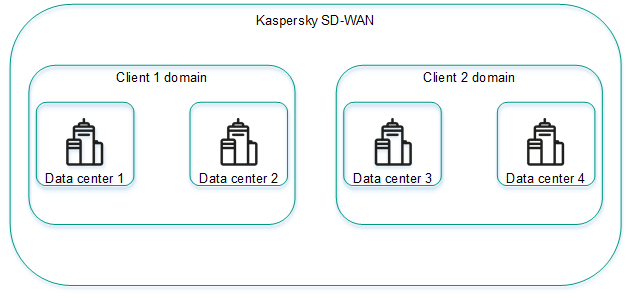
Example of an organization with domains and data centers
Managing domains
The list of domains is displayed in the Infrastructure section, in the Resources pane. Under the domains, the list displays data centers added to the domains.
Creating a domain
To create a domain:
- In the menu, go to the Infrastructure section.
This opens the resource management page. By default, the Network resources tab is selected, which displays the table of controllers.
- In the upper part of the page, click + Domain.
- This opens a window; in that window, in the Name field, enter the name of the domain. The maximum length of the name is 50 characters.
- If necessary, in the Description field, enter a brief description of the domain. The maximum length of the description is 100 characters.
- Click Create.
The domain is created and displayed in the Resources pane.
You can add data centers to a domain when you add data centers.
Page top
Editing a domain
To edit a domain:
- In the menu, go to the Infrastructure section.
This opens the resource management page. By default, the Network resources tab is selected, which displays the table of controllers.
- In the Resources pane, click the settings icon → Edit next to the domain that you want to edit.
- This opens a window; in that window, edit the name and/or description of the domain, if necessary.
- Click Save.
The domain is modified and displayed in the Resources pane.
Page top
Deleting a domain
Before deleting a domain, you need to delete data centers that have been added to the domain.
Deleted domains cannot be restored.
To delete a domain:
- In the menu, go to the Infrastructure section.
This opens the resource management page. By default, the Network resources tab is selected, which displays the table of controllers.
- In the Resources pane, click the settings icon → Delete next to the domain that you want to delete.
- In the confirmation window, click Delete.
The domain is deleted and is no longer displayed in the Resources pane.
Page top
Managing data centers
Lists of data centers are displayed in the Infrastructure in the Resources pane under domains. Before adding data centers, you must create at least one domain.
Adding a data center
To add a data center:
- In the menu, go to the Infrastructure section.
This opens the resource management page. By default, the Network resources tab is selected, which displays the table of controllers.
- In the upper part of the page, click + Data center.
- This opens a window; in that window, in the Name field, enter the name of the data center. The maximum length of the name is 50 characters.
- If necessary, in the Description field, enter a brief description of the data center. The maximum length of the description is 100 characters.
- In the Domain drop-down list, select the created domain to which you want to add the data center. After adding the data center, you can move it to a different domain.
- If you want to deploy virtual network functions and run scripts on CPE devices, in the VNFM URL field, enter the web address of the virtual network function manager to which the orchestrator connects. To verify that the VNFM is available, you can click Test connection.
- If necessary, in the Location field, enter the geographical address of the data center.
- Click Create.
The data center is added and displayed in the Resources pane.
Editing a data center
To edit a data center:
- In the menu, go to the Infrastructure section.
This opens the resource management page. By default, the Network resources tab is selected, which displays the table of controllers.
- In the Resources pane, click the settings icon → Edit next to the data center you want to edit.
- This opens a window; in that window, if necessary, edit the following settings:
- Name of the data center
- Brief description of the data center
- Web address of the Virtual Network Function Manager
- Address of the data center
- Click Save.
The data center is modified and updated in the Resources pane.
Page top
Migrating a data center to a different domain
To migrate a data center to a different domain:
- In the menu, go to the Infrastructure section.
This opens the resource management page. By default, the Network resources tab is selected, which displays the table of controllers.
- In the Resources pane, click the settings icon → Migrate next to the data center you want to migrate to a different domain.
- This opens a window; in that window, select the created domain to which you want to migrate your data center.
- Click Migrate.
The data center is migrated to the new domain and displayed under the new domain in the Resources pane.
Page top
Deleting a data center
Deleting a data center makes managing controllers, VIMs, and management subnets impossible. You also no longer can specify the Zabbix proxy server for configuring solution component monitoring.
Deleted data centers cannot be restored.
To delete a data center:
- In the menu, go to the Infrastructure section.
This opens the resource management page. By default, the Network resources tab is selected, which displays the table of controllers.
- In the Resources pane, click the settings icon → Delete next to the data center you want to delete.
- In the confirmation window, click Delete.
The data center is deleted and is no longer displayed in the Resources pane.
Page top
Managing management subnets
To display the table of management subnets, go to the Infrastructure menu section, click the added data center, and select the IPAM → Subnet tab. Information about management subnets is displayed in the following columns of the table:
- Name is the name of the management subnet.
- Type is the type of the subnet. Only management subnets are presently supported.
- CIDR is the IPv4 prefix of the management subnet.
- Gateway are IPv4 addresses of gateways that the management subnet assigns to virtual network functions.
- IP range are IP address ranges from which the management subnet assigns IP addresses to CPE devices and virtual network functions.
- DNS are IPv4 addresses of the DNS servers that the management subnet assigns to virtual network functions.
- Static routes are source and destination IPv4 addresses of static routes that the management subnet assigns to virtual network functions.
- Usage is the number of IP addresses that the management subnet has assigned to CPE devices and virtual network functions.
The table of CPE devices and virtual network functions to which the management subnet has assigned IP addresses is displayed on the Usage tab. Information about CPE devices and virtual network functions is displayed in the following table columns:
- Name is the name of the management subnet that assigned an IP address to the CPE or virtual network function.
- IP is the IP address assigned to the CPE device or virtual network function.
- Client name is the name of the CPE device or virtual network function.
- Client type is information about whether the control subnet has assigned an IP address to the CPE device or virtual network function:
- VNF
- CPE
- Tenant is the tenant to which the CPE device was added or virtual network function was assigned.
The actions you can perform with the tables are described in the Managing solution component tables instructions.
Creating a management subnet
To create a management subnet:
- In the menu, go to the Infrastructure section.
This opens the resource management page. By default, the Network resources tab is selected, which displays the table of controllers.
- In the Resources pane, select the created domain, then select the added data center in which you want to create the management subnet. After the management subnet is created, it cannot be moved to a different data center.
- Select the IPAM tab.
A table of management subnets is displayed.
- In the upper part of the page, click + Subnet.
- In the Name field, enter the name of the management subnet.
- In the IP version drop-down list, select the version of IP addresses in the management subnet:
- IPv4 Default value.
- IPv6
- In the CIDR field, enter the IPv4 prefix of the management subnet.
- If you want the management subnet to assign a particular gateway to virtual network functions, enter the IPv4 address of the gateway in the Gateway field.
- Specify the IP address range from which the management subnet assigns IP addresses to CPE devices and virtual network functions. To do so, under IP range, click + Addand in the displayed fields, enter the starting and ending values of the IP address range.
The IP address range is specified and displayed in the IP range section. You can specify multiple IP address ranges or delete an IP address range. To delete an IP address range, click the delete icon
 next to it.
 - Specify the DNS server that the management subnet assigns to virtual network functions. To do so, under DNS, click + Add and in the displayed field, enter the IPv4 address of the DNS server.
The DNS server is specified and displayed in the DNS section. You can specify multiple DNS servers or delete a DNS server. To delete a DNS server, click the delete icon
next to it. - Specify the static route that the management subnet assigns to virtual network functions. To do so, under Static routes, click + Add and in the displayed fields, enter the source and destination IPv4 addresses of the static route.
The static route is specified and displayed in the Static routes section. You can specify multiple static routes or delete a static route. To delete a static route, click the delete icon
next to it. - Click Create.
The management subnet is created and displayed in the table.
Page top
Editing a management subnet
To edit a management subnet:
- In the menu, go to the Infrastructure section.
This opens the resource management page. By default, the Network resources tab is selected, which displays the table of controllers.
- In the Resources pane, select the created domain, then select the added data center in which you created the management subnet.
- Select the IPAM tab.
A table of management subnets is displayed.
- Click Management → Edit next to the management subnet that you want to edit.
- This opens a window; in that window, edit the following settings, if necessary:
- Name of the management subnet
- IPv4 prefix of the management subnet
- IPv4 addresses of gateways that the management subnet assigns to virtual network functions
- IP address ranges from which the management subnet assigns IP addresses to CPE devices and virtual network functions
- DNS servers that the management subnet assigns to virtual network functions
- Static routes that the management subnet assigns to virtual network functions
- Click Save.
The management subnet is modified and updated in the table.
Page top
Deleting a management subnet
Deleted management subnets cannot be restored.
To delete a management subnet:
- In the menu, go to the Infrastructure section.
This opens the resource management page. By default, the Network resources tab is selected, which displays the table of controllers.
- In the Resources pane, select the created domain, then select the added data center in which you created the management subnet.
- Select the IPAM tab.
A table of management subnets is displayed.
- Click Management → Delete next to the management subnet that you want to delete.
- In the confirmation window, click Delete.
The management subnet is deleted and is no longer displayed in the table.
Page top
Managing controllers
To display the table of controllers, go to the Infrastructure menu section, click the created data center, and select the Network resources tab. Information about controllers is displayed in the following columns of the table:
- Name is the name of the controller.
- Transport/service strategy is the being used.
- Controller nodes are IP addresses of controller nodes.
- Connection type is the type of connection of CPE devices to the controller:
- Unicast
- Multicast
- Cluster status is the status of the cluster of controller nodes:
- Up means the cluster is operating normally.
- DEGRADED means an error occurred during the operation of the cluster.
- Down means the cluster is not operational.
- Node statuses is the status of controller nodes:
- Connected (primary) means the node is connected to the controller and is the primary node in the cluster.
- Connected (single) means the node is connected to the controller and is the only node in the cluster.
- Connected (secondary) means the node is connected to the controller and is a secondary node in the cluster.
- Disconnected means the node is not connected to the controller.
- Not in cluster means the node is not added to a cluster.
- Unavailable means the node is not available.
- Unknown means the status of the node is unknown.
The actions you can perform with the table are described in the Managing solution component tables instructions.
Editing a controller
To edit a controller:
- In the menu, go to the Infrastructure section.
This opens the resource management page. By default, the Network resources tab is selected, which displays the table of controllers.
- Click Management → Edit next to the controller that you want to edit.
- This opens a window; in that window, in the Name field, enter the name of the controller. Range of values: 1 to 128 characters.
- If necessary, in the Description field, enter a brief description of the controller.
- In the Controller installation on <1>/<3>/<5> servers field, select the number of controller nodes.
- In the Connection type drop-down list, select the type of connection of CPE devices to the controller:
- Unicast
- Multicast
- Configure the controller node:
- In the Address (IP or hostname) field, enter the IP address or hostname of the controller node.
- In the gRPC port field, enter the gRPC port number of the controller node.
- In the JGroups port field, enter the jGroups port number of the controller node.
- If you want to make the controller node the primary node, select the Primary option.
You can configure multiple controller nodes.
- Click Save.
The controller is modified and updated in the table.
Page top
Reprovisioning a controller
During reprovisioning, controller properties are reset to their default values. This may help resolve errors.
To reprovision the controller:
- In the menu, go to the Infrastructure section.
This opens the resource management page. By default, the Network resources tab is selected, which displays the table of controllers.
- Click Management → Reprovision next to the controller that you want to reprovision.
- In the confirmation window, click Reprovision.
The controller is reprovisioned.
Page top
Restoring a controller
You can download a file with controller settings and later use the file to restore the controller if necessary.
To restore a controller:
- In the menu, go to the Infrastructure section.
This opens the resource management page. By default, the Network resources tab is selected, which displays the table of controllers.
- Click Management → Download backup file next to the controller whose settings file you want to download.
A file with controller settings in YAML format is saved to your local device.
- Click Management → Restore next to the controller that you want to restore.
- This opens a window; in that window, specify the path to the downloaded file with controller settings.
- Click Restore.
The controller is restored with settings from the controller settings file.
Page top
Enabling or disabling the maintenance mode on a controller
You can enable maintenance mode on the controller when performing maintenance work related to the SD-WAN network to minimize the impact of the controller on parts of the SD-WAN network that are not affected by the maintenance work. In maintenance mode, the controller monitors the status of the SD-WAN network, but does not take any action when the parameters of the SD-WAN network change. For example, in maintenance mode the controller does not rebuild links and paths, does not rewrite MAC addresses of service interfaces, or change transport services.
When you disable maintenance mode, the controller performs actions corresponding to the changes you made to the parameters of the SD-WAN network.
To enable or disable maintenance mode on the controller:
- In the menu, go to the Infrastructure section.
This opens the resource management page. By default, the Network resources tab is selected, which displays the table of controllers.
- Do one of the following:
- If you want to enable maintenance mode on the controller, click Management → Enable maintenance next to it.
- If you want to disable maintenance mode on the controller, click Management → Disable maintenance next to it.
Maintenance mode is enabled or disabled on the controller.
Page top
Deleting a controller
Deleted controllers cannot be restored.
To delete a controller:
- In the menu, go to the Infrastructure section.
This opens the resource management page. By default, the Network resources tab is selected, which displays the table of controllers.
- Click Management → Delete next to the controller that you want to delete.
- In the confirmation window, click Delete.
The controller is deleted and is no longer displayed in the table.
Page top
Managing controller properties
Properties regulate the operation of the controller. Each property has a change method that determines whether the property value can be changed and when the change takes effect. The following change methods are available:
- Read-only means the property cannot be changed.
- Reload means that when a property is changed, the orchestrator commits the new value to the database of the controller. The new value takes effect after the controller is restarted.
A property value that is in the database, but has not yet taken effect is called a planning value. You can delete a planning value before restarting the controller to keep the current value.
- Runtime means the new value takes effect immediately when the property is modified.
Modifying properties may lead to unstable operation of the controller, so we recommend contacting Kaspersky Technical Support before managing properties.
You can view the table of all controller properties or only changeable controller properties:
- To display the table of all controller properties, navigate to the Infrastructure section, click the added data center, select the Network resources tab, and click Management → Properties next to the controller.
- To display the table of changeable properties of the controller, navigate to the Infrastructure section, click the added data center, select the Network resources tab, click Management → Properties next to the controller and select the Changeable properties tab.
Information about controller properties is displayed in the following columns of the table:
- Change method is the change method of the property.
- Property is the name of the property.
- Current value is the current value of the property.
- Planned value is the planning value of the property. This column is displayed only on the Changeable properties tab.
The actions you can perform with the table are described in the Managing solution component tables instructions.
Description of editable controller properties
Modifying properties may lead to unstable operation of the controller, so we recommend contacting Kaspersky Technical Support before managing properties.
Property |
Description |
|
Buffer size, in bytes, for messages coming in from switches on the controller. |
|
Buffer size, in bytes, for messages going out to switches on the controller. |
|
The starting port number in the range of switch ports. Ports with the next three consecutive numbers are added to the range. For example, if you enter |
|
Whether the TCP_NODELAY parameter is used for management sessions between switches and the controller. Possible values:
|
|
Whether the epoll system is used by the controller when managing switches. Possible values:
|
|
Time in milliseconds after which management sessions between the switches and the controller go idle in absence of read or write operations. The countdown starts anew whenever a read or write operation is performed. |
|
Time in milliseconds after which management sessions between the switches and the controller go idle in absence of read operations. The countdown starts anew whenever a read operation is performed. |
|
Time in milliseconds after which management sessions between the switches and the controller go idle in absence of write operations. The countdown starts anew whenever a write operation is performed. |
|
Netty threads preferentially run on separate CPU cores for separate switches. Possible values:
|
|
Number of Netty threads for handling new switch connections. |
|
Path to the PEM file of the root certificate that was used to sign the OpenFlow certificate. |
|
Path to the PEM file of the encryption certificate for OpenFlow traffic between the controller and switches. |
|
Path to the PEM file with the private key of the OpenFlow certificate. |
|
When the Netty buffer of the management session between switches and the controller contains this number of bytes, the queue is used to write to the session. |
|
When the Netty buffer of the management session between switches and the controller contains this number of bytes, the queue is no longer used to write to the session. This property is used when the number of bytes reaches the |
|
The throughput of the policer on the switches when sending traffic packets through the management session between the switches and the controller. Traffic packets are copied by interception flow rules. |
|
Time, in seconds, after which flow rules automatically created by the controller when processing the first intercepted traffic packet are deleted on the switches to block subsequent packets. The countdown starts anew every time the flow rule is applied. |
|
Bonding of parallel links between two switches. Possible values:
|
|
Whether the equal cost algorithm is used when bonding links. Possible values:
If you specify |
|
Maximum number of links in a bonded link. |
|
Type of the bonded link group. Possible values:
|
|
Whether the controller periodically sends LLDP packets only to enabled ports to detect links between switches. Possible values:
|
|
Whether the switches relay LLDP packets to the controller only from enabled ports when the controller attempts to discover links between the switches. Possible values:
|
|
Interval in milliseconds for the controller sending LLDP packets through the switch links. |
|
Interval in milliseconds for the receiving side of switch links to receive LLDP packets and forward the LLDP packets to the controller. If no LLDP packets arrive through the link within the specified time, the controller considers the link unavailable. |
|
Whether switches send notifications to the controller whenever flow rules that send traffic packets to the controller are deleted. Possible values:
|
|
Interval in milliseconds for checking the connection of switches to the controller. |
|
Time in milliseconds within which disconnected switches must reconnect to the controller. |
|
Number of the last virtual network interface (VNI) in the range of switch interfaces. |
|
Number of the first virtual network interface in the range of switch interfaces. |
|
Whether link Dampening is used. Possible values:
|
|
Maximum time in milliseconds for which access to the link can be restricted. When the specified time elapses, all Dampening counters are reset. |
|
The number by which Penalty is incremented when the link changes state. |
|
The Penalty value at which access to the link is restricted. |
|
Time in milliseconds within which the Penalty must reach the |
|
The IEEE 802.1Q TPID value that is specified as the inner tag for traffic packets with Q-in-Q traffic classification. |
|
The IEEE 802.1Q TPID value that is specified as the outer tag for traffic packets with Q-in-Q traffic classification. |
|
Getting statistics on switches. Statistics contain information about network devices to which the switch is connected, as well as the ports being used. Possible values:
|
|
Value of the 'cookie' field in the message for requesting statistics from the switches. Possible values:
This property must be specified if for |
|
ID of the LLDP packet queue on the switches. |
|
Maximum size of the push notification queue on the switches. If this size is exceeded, the first push notification in the queue is deleted. |
|
Duration in seconds for which IP addresses and ports of switches are blocked after an attempt to connect to the controller with an invalid TLS certificate. |
|
Whether IP addresses and ports of switches are blocked after an attempt to connect to the controller with an invalid TLS certificate. Possible values:
|
|
Time in seconds within which the switches must make the number of attempts (specified in the |
|
The number of attempts of switches to connect to the controller with an invalid TLS certificate, after which the IP addresses and ports of the switches are blocked. |
|
This property is no longer used. |
|
This property is no longer used. |
|
Whether flow rules send traffic packets to the controller. Possible values:
|
|
This property is no longer used. |
|
Interval in milliseconds for checking the latency between the controller and the switches. |
|
Whether latency is checked between the controller and switches. Possible values:
|
|
Number of leading traffic packets on the switches, which is not counted towards statistics. |
|
Number of trailing traffic packets on the switches, which is not counted towards statistics. |
|
Size, in bytes, of chunks of serialized OpenFlow messages that the controller sends to the switches. |
|
Maximum number of blocks of serialized OpenFlow messages in the controller queue. |
|
This property is no longer used. |
|
This property is no longer used. |
|
This property is no longer used. |
|
This property is no longer used. |
|
Maximum number of paths in a segment. |
|
Maximum number of SPF paths for automatic balancing. |
|
Action that switches perform with traffic packets that are not in any of the OpenFlow tables. Possible values:
|
|
Whether Connectivity Fault Management (CFM) is used on links. Possible values:
|
|
Whether controller debug routines are used involving the gRPC protocol. Possible values:
|
|
Establishing links between VTEPs. Possible values:
|
|
Using all links as a last resort when routing traffic, regardless of the link quality. Possible values:
|
|
Link discovery by groups. Possible values:
|
|
Traffic encryption on links. Possible values:
|
|
Interval in minutes for updating the decryption key on links. |
|
Monitoring of errors on links. Possible values:
|
|
Threshold value of the number of errors per second on links. |
|
Interval in seconds for measuring the number of errors on links and link utilization. |
|
Whether Forward Error Correction (FEC) is used on links. Possible values:
|
|
Ratio of original traffic packets to additional packets with redundant code. Enter a value in the |
|
The maximum time, in milliseconds, during which a traffic packet can stay in the queue for FEC to apply. |
|
Monitoring of jitter on links. Possible values:
|
|
Time threshold of jitter on links, in milliseconds. |
|
Monitoring of latency on links. Possible values:
|
|
Latency threshold on links, in milliseconds. |
|
Interval in seconds for comparing the received monitoring figures with the specified thresholds of latency, jitter, and packet loss on links. |
|
Monitoring of latency, jitter, and traffic packet loss on links. Possible values:
You can specify the monitoring protocol using the |
|
Size in bytes of the additional buffer in each LLDP packet for latency, jitter, and packet loss monitoring figures. This property must be specified if for |
|
Protocol for monitoring of latency, jitter, and traffic packet loss on links. Possible values:
|
|
The multiplier that the controller applies to delay, jitter, and packet loss monitoring figures. This property must be specified if for |
|
Monitoring of traffic packet loss on links. Possible values:
|
|
Threshold value of the traffic packet loss percentage on links. |
|
Interval in seconds for automatic detection of the MTU figure on links. |
|
How long the controller waits for a PMTUD LLDP packet, in milliseconds. If the controller does not receive a PMTUD LLDP packet within this time, the controller concludes that a packet of this size cannot be transmitted over the link. |
|
Interval in seconds for monitoring of link thresholds. |
|
Threshold monitoring on links. Possible values:
|
|
Number of successful checks in a row for a link to be unblocked. A check is performed once per second. |
|
Monitoring of link utilization (bandwidth usage). Possible values:
|
|
Threshold value of link utilization as a percentage of the bandwidth of service interfaces. |
|
Concurrent sending of LLDP packets by the controller for link discovery. Possible values:
|
|
Minimum number of streams for concurrent sending of LLDP packets by the controller. This property must be specified if for |
|
Maximum number of streams for concurrent sending of LLDP packets by the controller. This property must be specified if for |
|
Maximum queue size when the controller is sending LLDP packets concurrently. This property must be specified if for |
|
The reserve service interface becomes reserve again if the old service interface becomes operational again. Possible values:
|
|
Accumulation of physical operations on the controller, such as connecting a switch or a port, to perform the operations when the specified time elapses. Possible values:
You can specify the time using the |
|
Time in seconds after which the physical operations accumulated on the controller are carried out. This property must be specified if for |
|
Time in seconds after which the physical operations accumulated on the controller are carried out. The countdown starts anew whenever a physical operation appears. This property can be specified if for |
|
System property. Editing this property may render the controller inoperable. |
|
System property. Editing this property may render the controller inoperable. |
Editing a controller property
Changes you make to the controller properties with the Runtime change method take effect immediately. Changes you make to controller properties with the Reload change method take effect after the controller is restarted.
To change a controller property:
- In the menu, go to the Infrastructure section.
This opens the resource management page. By default, the Network resources tab is selected, which displays the table of controllers.
- Click Management → Properties next to the controller for which you want to change a property.
The controller properties page is displayed. By default, the All properties tab is selected, which displays a table of all controller properties.
- Select the Changeable properties tab.
A table of editable properties of the controller is displayed.
- Click Management → Edit next to the controller property that you want to edit.
- This opens a window; in that window, in the Planned value field, enter the new value of the controller property.
- Click Save.
The new value of a property with the Runtime method is displayed in the Current value column. The new value of a property with the Reload method is displayed in the Planned value column.
Deleting planning values of controller properties
You can delete a planning value to undo a controller property change. This action is applicable only to properties that have the Reload method.
Deleted planning values of controller properties cannot be restored.
To delete planning values of controller properties:
- In the menu, go to the Infrastructure section.
This opens the resource management page. By default, the Network resources tab is selected, which displays the table of controllers.
- Click Management → Properties next to the controller for which you want to delete planning values of properties.
The controller properties page is displayed. By default, the All properties tab is selected, which displays a table of all controller properties.
- Select the Changeable properties tab.
A table of editable properties of the controller is displayed.
- Delete the planning values of controller properties in one of the following ways:
- If you want to delete the planning value of an individual property of the controller, click Management → Delete planned value next to that property.
- If you want to delete planning values of all controller properties, in the upper part of the table, click the settings icon → Delete all planned values.
- In the confirmation window, click Delete.
The planning values of controller properties are deleted.
Page top
Resetting controller properties to default values
To reset controller properties to default values:
- In the menu, go to the Infrastructure section.
This opens the resource management page. By default, the Network resources tab is selected, which displays the table of controllers.
- Click Management → Properties next to the controller whose properties you want to reset to default values.
The controller properties page is displayed. By default, the All properties tab is selected, which displays a table of all controller properties.
- Select the Changeable properties tab.
A table of editable properties of the controller is displayed.
- Reset the controller properties in one of the following ways:
- If you want to reset an individual property of the controller to its default value, click Management → Reset property next to that property.
- If you want to reset all controller properties to their default values, click the settings icon in the upper part of the table → Reset all properties.
- In the confirmation window, click Reset.
The controller properties are reset to their default values.
Page top
Viewing information about controller nodes
To view information about controller nodes:
- In the menu, go to the Infrastructure section.
This opens the resource management page. By default, the Network resources tab is selected, which displays the table of controllers.
- Click Management → Configuration menu next to the controller for which you want to view information about nodes.
This opens the controller configuration menu. By default, you are taken to the Controller nodes section, which displays a table of controller nodes. Information about controller nodes is displayed in the following columns of the table:
- Address is the IP address of the controller node.
- Status is the status of the controller node:
- Connected (primary) means the node is connected to the controller and is the primary node in the cluster.
- Connected (single) means the node is connected to the controller and is the only node in the cluster.
- Connected (secondary) means the node is connected to the controller and is a secondary node in the cluster.
- Disconnected means the node is not connected to the controller.
- Not in cluster means the node is not added to a cluster.
- Unavailable means the node is not available.
- Unknown means the status of the node is unknown.
- gRPC port is the number of the gRPC port of the controller node.
- JGroups port is the JGroups port number of the controller node.
- Version is the version of the controller node software.
The actions that you can perform with the table are described in the Managing solution component tables instructions.
- If you want to view statistics for a controller node, click Management →Statistics next to the node.
- If you want to view the properties of a controller node, click Management → Node properties next to the node.
Managing a VIM
You can deploy a VIM in one of your data centers or on a uCPE device. Deploying the VIM in a data center implies centralized management of the virtual network function lifecycle. Deploying the VIM on a uCPE device lets you deliver virtual network functions to remote data centers and manage them locally.
To display the table of VIMs, go to the Infrastructure menu section, click the created data center, and select the IPAM → Compute resources tab. Information about VIMs is displayed in the following columns of the table:
- Name is the name of the VIM.
- Type is the type of the VIM. Kaspersky SD-WAN uses the OpenStack cloud platform as the VIM.
- Function is the data center or uCPE device on which the VIM is deployed.
- VIM IP is the IP address of the VIM.
- Status is the connection status of the VIM to the OpenStack cloud platform:
- Connected
- Disconnected
- SDN cluster is the SDN cluster to which OpenStack is connected.
- Behind NAT lets you specify whether the VIM is behind NAT (Network Address Translation):
- Yes
- No
The actions you can perform with the table are described in the Managing solution component tables instructions.
Configuring a VIM deployed in a data center
To configure a VIM deployed in a data center:
- In the menu, go to the Infrastructure section.
This opens the resource management page. By default, the Network resources tab is selected, which displays the table of SD-WAN Controllers.
- In the Resources pane, select the created domain, then select the added data center in which you deployed the VIM.
- Select the Compute resources tab.
A table of VIMs is displayed.
- In the upper part of the page, click + VIM.
- This opens a window; in that window, in the Name field, enter the name of the VIM.
- In the IP field, enter the IP address or domain name for connecting the orchestrator to the VIM.
- In the Port field, enter the port number for connecting the orchestrator to the VIM identification service. Default value:
5000. - In the Protocol drop-down list, select the protocol for connecting the orchestrator to the VIM:
- http Default value.
- https
- In the Login and Password fields, enter the user name and password of an account with administrator privileges to authenticate the orchestrator in the OpenStack cloud platform. If authentication is successful, the orchestrator gains access to management of virtual infrastructure that is available to the administrator.
- Specify advanced orchestrator authentication settings in the OpenStack cloud platform:
- In the Administrator project field, enter the name of the administrator project for orchestrator authentication in this administrator project.
- In the Domain field, enter the OpenStack domain name for orchestrator authentication in this OpenStack domain.
- In the Behind NAT drop-down list, select whether the VIM is behind NAT:
- Enabled to indicate that the VIM is behind NAT and network address translation happens when the VIM interacts with the SD-WAN instance.
- Disabled to indicate that the VIM is not behind NAT. Default value.
- Specify the overcommitment ratios for physical resources:
- In the CPU overcommitment field, enter the CPU core overcommitment ratio. Default value:
1. - In the RAM overcommitment field, enter the RAM overcommitment ratio. Default value:
1. - In the Disk overcommitment field, enter the disk space overcommitment ratio. Default value:
1.
Overcommitment ratios let you provision virtual machines with more virtual resources than physically present. This is possible because virtual machines do not simultaneously use all available physical resources to the maximum. For example, if you specify a disk space overcommitment factor of
3, the available virtual disk space can be three times as large as the disk space physically available on the host.When configuring overcommitment, you must consider how the capabilities of your hardware relate to the requirements of the virtual machines. If you specify a high overcommitment ratio for physical resources and virtual machines happen to use them up, this may lead to the network lagging and/or parts of network becoming completely unavailable.
- In the CPU overcommitment field, enter the CPU core overcommitment ratio. Default value:
- In the Parallelism field, enter the maximum number of simultaneous operations between the orchestrator and the VIM. Default value:
1. This setting lets you reduce the overall processing time for operations, but creates an additional load on the virtual infrastructure.We recommend not changing the default value unless the overall operation processing speed is critical for you.
- In the SDN cluster drop-down list, select the SDN cluster to which OpenStack is connected. If OpenStack is not connected to an SDN cluster, select None.
- In the Maximum number of VLANs field, enter the maximum number of VLANs that the VIM may use. This setting lets the orchestrator keep track of the number of segments available for use. Range of values: 0 to 4,094.
- If the VIM supports SR-IOV, enter the physnet name in the SR-IOV physical network field. The orchestrator uses the SR-IOV physical network name to connect virtual machines with the SR-IOV interface type.
- If you are using a network with the VLAN segmentation type for management, in the VLAN physical network field, enter the VLAN tag.
- If you selected an SDN cluster in the SDN cluster drop-down list, configure the connection to that cluster:
- If you want to map the logical networks of the SD-WAN instance to a physical network, enter the physnet name in the OpenStack physical network field.
- In the Interface group drop-down list, select the port group through which all OpenStack nodes are connected to the SDN cluster.
- In the Control group drop-down list, select the port group through which the OpenStack control nodes are connected to the SDN cluster.
- If necessary, in the Compute group drop-down list, select the port group through which OpenStack compute nodes are connected to the SDN cluster.
- If in the SDN cluster drop-down list, you selected None, configure the network:
- If you want to map the flat networks of the SD-WAN instance to a physical network, enter the physnet name in the Flat physical network field.
- If you want to map the VXLAN of the SD-WAN instance to a physical network, enter the physnet name in the VXLAN physical network field.
- In the Control network segmentation drop-down list, select the type of segmentation for isolating and securing control plane traffic in the SD-WAN structure:
- VLAN
- VXLAN
- In the Control segment ID field, enter the segment ID of the management network. The range of values depends on the value selected in the Control network segmentation drop-down list:
- If you selected VLAN, the range of values is 0 to 4,095.
- If you selected VXLAN, the range of values is 0 to 16,000,000.
- In the Port security drop-down list, select whether you want to enable the Port security function:
- Enabled
- Disabled
- In the Permit CIDR field, enter the IPv4 prefox of the allowed subnet for the management network.
- Click Create.
The VIM is created and displayed in the table on the Compute resources tab.
Page top
Configuring a VIM deployed on a uCPE device
To configure a VIM deployed on a uCPE device, you must specify the settings of the VIM in a uCPE template. VIM settings specified in a uCPE template are automatically applied to all CPE devices that are using this uCPE template.
To configure a VIM deployed on a uCPE device:
- In the menu, go to the SD-WAN → CPE templates section.
A table of CPE templates is displayed.
- Click the uCPE template in which you want to configure a VIM.
The settings area is displayed in the lower part of the page. You can expand the settings area to fill the entire page by clicking the expand icon
 . By default, the Information tab is selected, which displays general information about the CPE template.
 - Select the VIM tab.
The VIM settings are displayed.
- In the Port field, enter the port number for connecting the orchestrator to the VIM identification service. Default value:
5000. - In the Protocol drop-down list, select the protocol for connecting the orchestrator to the VIM:
- http Default value.
- https
- In the Login and Password fields, enter the user name and password of an account with administrator privileges to authenticate the orchestrator in the OpenStack cloud platform. If authentication is successful, the orchestrator gains access to managing the virtual infrastructure that is available to the administrator.
- Specify advanced orchestrator authentication settings in the OpenStack cloud platform:
- In the Administrator project field, enter the name of the administrator project for orchestrator authentication in this project.
- In the Domain field, enter the OpenStack domain name for orchestrator authentication in this domain.
- If you are using a network with the VLAN segmentation type for management, in the VLAN physical network field, enter the VLAN tag.
- In the Behind NAT drop-down list, select whether the VIM is behind NAT:
- Enabled to indicate that the VIM is behind NAT and network address translation happens when it interacts with the SD-WAN instance.
- Disabled to indicate that the VIM is not behind NAT. Default value.
- Specify the overcommitment ratios for physical resources:
- In the CPU overcommitment field, enter the CPU core overcommitment ratio. Default value:
1. - In the RAM overcommitment field, enter the RAM overcommitment ratio. Default value:
1. - In the Disk overcommitment field, enter the disk space overcommitment ratio. Default value:
1.
Overcommitment ratios let you provision virtual machines with more virtual resources than physically present. This is possible because, as a rule, virtual machines do not simultaneously use all available physical resources to the maximum. For example, if you specify a disk space overcommitment factor of
3, the available virtual disk space can be three times as large as the disk space physically available on the host.When configuring overcommitment, you must consider how the capabilities of your hardware relate to the requirements of the virtual machines. If you specify a high overcommitment ratio for physical resources and virtual machines happen to use them up, this may lead to the network lagging and/or parts of network becoming completely unavailable.
- In the CPU overcommitment field, enter the CPU core overcommitment ratio. Default value:
- In the Maximum number of VLANs field, enter the maximum number of VLANs that the VIM may use. This setting lets the orchestrator keep track of the number of segments available for use. Range of values: 0 to 4,094.
- In the upper part of the settings area, click Save to save CPE template settings.
Editing a VIM deployed in a data center
To edit a VIM deployed in a data center:
- In the menu, go to the Infrastructure section.
This opens the resource management page. By default, the Network resources tab is selected, which displays the table of controllers.
- In the Resources pane, select the created domain, then select the added data center in which you deployed the VIM.
- Select the Compute resources tab.
A table of VIMs is displayed.
- Click Management → Edit next to the VIM that you want to edit.
- This opens a window; in that window, edit the VIM settings, if necessary. For a description of the settings, refer to the instructions for configuring a VIM deployed in a data center.
- Click Save.
The VIM is modified and updated in the table.
Page top
Viewing computing resources being used by a VIM
You can view the utilization of the following computing resources by the VIM:
- CPU
- RAM
- Disk space
- Network segments
To view the computing resources used by the VIM:
- In the menu, go to the Infrastructure section.
This opens the resource management page. By default, the Network resources tab is selected, which displays the table of controllers.
- In the Resources pane, select the created domain, then select the added data center in which you deployed the VIM.
- Select the Compute resources tab.
A table of VIMs is displayed.
- Click Management → Show usage next to the VIM.
This opens a window with information about the computing resources used by the VIM.
Page top
Deleting a VIM
Deleted VIMs cannot be restored.
To delete a VIM:
- In the menu, go to the Infrastructure section.
This opens the resource management page. By default, the Network resources tab is selected, which displays the table of controllers.
- In the Resources pane, select the created domain, then select the added data center in which you deployed the VIM.
- Select the Compute resources tab.
A table of VIMs is displayed.
- Click Management → Delete next to the VIM that you want to delete.
- In the confirmation window, click Delete.
The VIM is deleted and is no longer displayed in the table.
Page top
Managing users and their access permissions
To restrict access to the administrator portal and self-service portal, as well as to sections, subsections and functions, the solution implements a role-based access control model (Role Based Access Control; RBAC). User accounts can have the following roles:
- An administrator has access to the administrator portal and self-service portal.
- A tenant has access only to the self-service portal.
Deploying the solution creates the Administrator user with the administrator role and the User user with the tenant role.
You can create local users, LDAP users, and LDAP user groups. The solution does not support creating local user groups. Credentials of local users are stored in the orchestrator database. Credentials of LDAP users and LDAP user groups are stored on a remote server. Supported servers include the remote OpenLDAP server with Simple SSL authentication, as well as Microsoft Active Directory with Kerberos authentication and Kerberos SSL authentication.
You must first create an LDAP connection that the orchestrator uses to connect to the remote server, and then create LDAP users and/or LDAP user groups. Created LDAP users and LDAP user groups can log in to the orchestrator web interface using their credentials.
Two-factor authentication
To improve the overall security level of the solution, you can require two-factor authentication of users using the Time-based one-time password (TOTP) algorithm. You can enable or disable two-factor authentication for all users. You can also enable or disable two-factor authentication when creating or editing local users, LDAP users, and LDAP groups.
If two-factor authentication is enabled for a user, a unique QR code is generated the next time that user logs in to the orchestrator web interface. The user must scan a QR code using a software or hardware RFC 6238 compliant authenticator, such as Kaspersky Password Manager, Google Authenticator, Yandex Key, and Microsoft Authenticator. The authenticator generates a unique code that the user must enter to complete two-factor authentication and log in to the orchestrator web interface. If the user enters the unique code incorrectly more than five times, that user is blocked for 30 minutes.
After completing two-factor authentication, the user must enter a user name, password, and a unique code to log into the orchestrator web interface. If necessary, you can make the user complete two-factor authentication again.
If the time discrepancy between the orchestrator and the authenticator is greater than 30 seconds, two-factor authentication may fail. We recommend synchronizing the time on the orchestrator and the authenticator using an NTP server.
Access permissions
If necessary, you can create access permissions that determine which sections and subsections of the orchestrator web interface, and which actions are available to which users, and assign these access rights when creating or editing LDAP users and/or LDAP user groups. For example, you can create an access permission that prohibits gaining access to the Catalog section and creating network service templates.
By default, LDAP users and groups have the Full Access permission, which grants full access to all functionality of the solution.
Confirmation requests
When creating or editing a user, you must specify if you want to have a confirmation request automatically created whenever this user performs an action. Confirmation requests can be confirmed, denied, or deleted. When a request is confirmed, the associated action is performed. Denied confirmation requests are saved in the orchestrator web interface.
User sessions
The following functions are used to manage user sessions:
- Limiting the duration of user sessions. If a user remains idle for 3600 seconds (one hour) after logging into the orchestrator web interface, the user session is automatically ended. You can manually specify the period of inactivity that triggers automatic logout.
- Termination of user sessions. If multiple employees use the same user account credentials to log in to the orchestrator web interface, any of these employees can end the sessions of other users.
Managing access permissions
The list of access permissions is displayed in the Users section of the Permissions tab. By default, the Full access permission is created, which grants full access to the orchestrator web interface and is automatically assigned to users and LDAP user groups if you do not assign them a different access permission.
The actions you can perform with the list are described in the Managing solution component tables instructions.
Creating access permissions
To create an access permission:
- In the menu, go to the Users section.
The user management page is displayed. The Users tab, which is selected by default, displays the table of users.
- Select the Permissions tab.
The list of access permissions is displayed.
- In the upper part of the list, click + Permission.
- In the displayed settings area, in the Name field, enter the name of the access permission. Maximum length: 250 characters.
- In the Access rights section next to the sections and subsections of the orchestrator web interface, select one of the following values:
- Editing to allow the users to view the section or subsection and perform all available tasks in it.
- Viewing to allow users only to view the section or subsection.
- No access to prevent users from viewing the section or subsection.
If you want the subsections to inherit the value selected for the section, select the Apply to subsections check box. This check box is cleared by default.
- Click Create.
The access permission is created and displayed in the list.
You can assign an access permission when creating or editing a user, or when creating or editing an LDAP user group.
Page top
Editing access permissions
To edit an access permission:
- In the menu, go to the Users section.
The user management page is displayed. The Users tab, which is selected by default, displays the table of users.
- Select the Permissions tab.
The list of access permissions is displayed.
- Click the access permission that you want to edit.
- In the displayed settings area, edit the following settings, if necessary:
- Name of the access permission
- Sections and subsections of the orchestrator web interface and actions available to users
- Click Save.
The access permission is modified and updated in the list.
Page top
Cloning access permissions
You can clone an access permission to create an identical access permission with a different name.
To clone an access permission:
- In the menu, go to the Users section.
The user management page is displayed. The Users tab, which is selected by default, displays the table of users.
- Select the Permissions tab.
The list of access permissions is displayed.
- Click the access permission that you want to clone.
- In the upper part of the displayed settings area, click Management → Clone.
- This opens a window; in that window, enter the name of the new access permission.
- Click Clone.
A copy of the access right with the new name is added to the list.
Page top
Removing an access permission
Deleted access permissions cannot be restored.
To remove an access permission:
- In the menu, go to the Users section.
The user management page is displayed. The Users tab, which is selected by default, displays the table of users.
- Select the Permissions tab.
The list of access permissions is displayed.
- Click the access permission that you want to delete.
- In the upper part of the displayed settings area, click Management→ Delete.
- In the confirmation window, click Delete.
The access permission is deleted and is no longer displayed in the list.
Page top
Managing LDAP connections
The LDAP connection table is displayed in the Users on the LDAP connection tab. Information about LDAP connections is displayed in the following table columns:
- Name is the name of the LDAP connection.
- Type is the type of the connection. This column always displays LDAP.
- Host is the host name of the remote server.
The actions you can perform with the table are described in the Managing solution component tables instructions.
Creating an LDAP connection
If you want LDAP users or LDAP user groups to be able to log in to the orchestrator web interface using their credentials, you must first create an LDAP connection that the orchestrator uses to connect to the remote server, and then create your LDAP users or LDAP user groups.
To create an LDAP connection:
- In the menu, go to the Users section.
The user management page is displayed. The Users tab, which is selected by default, displays the table of users.
- Select the LDAP connection tab.
A table of LDAP connections is displayed.
- Click + LDAP.
- In the displayed settings area, in the Name field, enter the name of the LDAP connection.
- In the Domain field, enter the FQDN of the domain of the remote server.
- In the Domain alias field, enter the alias or NETBIOS name of the domain. Users enter the alias, NETBIOS name, or FQDN of the domain when logging into the orchestrator web interface.
- In the LDAP host field, enter the host name of the remote server. The following host name formats are supported:
ldap://<host name>:<port number>for a standard LDAP server. The default port is 389.ldaps://<host name>:<port number>for an LDAP server with SSL authentication. The default port is 636.
For example, if you enter
ldap://example.com:100, the host name of the remote server is 'example.com' and the port number is 100. - In the Base DN field, enter the base distinguished name that the orchestrator uses as the starting point for searching user accounts in the remote server directory. The following base distinguished name formats are supported:
- To search in OpenLDAP, enter the base distinguished name in the
OU=<value>,OU=<value>format, whereOUis the structure of organizational units in the remote server directory. For example, if you enterOU=OU_example1,OU=OU_example2, the starting point for searching user accounts is organizational unit OU_example2, which is nested in OU_example1. - To search in Microsoft Active Directory, enter the base distinguished name in the
DC=<value>,DC=<value>, whereDCsare the domain components of the remote server. For example, if you enterDC=example,DC=com, the starting point for searching user accounts is the 'example.com' domain.
- To search in OpenLDAP, enter the base distinguished name in the
- In the Search attribute drop-down list, select the attribute that the orchestrator uses to search for user accounts in the remote server directory:
- In the Bind DN field, enter the distinguished name for authenticating the orchestrator on the remote server. The following distinguished name formats are supported:
- For authentication in openLDAP, enter a value in the
UID=<value>,OU=<value>format, whereUIDis the user ID andOUis the organizational unit structure in the remote server directory where the user is located. For example, if you enterUID=user_example,OU=OU_example, user user_example from organizational unit OU_example is used for authenticating the orchestrator on the remote server. For authentication in Microsoft Active Directory, enter a value in the CN=<value>,OU=<value>,DC=<value>,DC=<value>, where CN is the common name of the user, OU is the organizational unit structure in the directory of the remote server where the user is located, and the DCs are the user's domain components. For example, if you enterCN=user_example,OU=OU_example,DC=example,DC=com, user user_example in organizational unit OU_example in the example.com domain is used for authenticating the orchestrator on the remote server.
- For authentication in openLDAP, enter a value in the
- In the Bind password field, enter the remote server password for authenticating the orchestrator on the remote server. To see the entered password, you can click the show icon
 .
. - To check if the remote server is available, click Test authentication.
- Click Create.
The LDAP connection is created and displayed in the table.
Page top
Editing an LDAP connection
To edit an LDAP connection:
- In the menu, go to the Users section.
The user management page is displayed. The Users tab, which is selected by default, displays the table of users.
- Select the LDAP connection tab.
A table of LDAP connections is displayed.
- Click the LDAP connection that you want to edit.
- In the displayed settings area, edit the following LDAP connection settings, if necessary: For a description of the settings, see the instructions for creating a LDAP connection.
- Click Save.
The LDAP connection is modified and updated in the table.
Page top
Changing the password of an LDAP connection
You can change the remote server password that was specified when the LDAP connection was created and make the orchestrator use the new password to authenticate with the remote server.
To change the password of an LDAP connection:
- In the menu, go to the Users section.
The user management page is displayed. The Users tab, which is selected by default, displays the table of users.
- Select the LDAP connection tab.
A table of LDAP connections is displayed.
- Click the LDAP connection for which you want to change the password.
- In the upper part of the displayed settings area, click the Management button → Change password.
- This opens a window; type the new password in the New password and Password confirmation text boxes.
- Click Save.
The LDAP connection password is changed.
Page top
Deleting an LDAP connection
Deleted LDAP connections cannot be restored.
To delete an LDAP connection:
- In the menu, go to the Users section.
The user management page is displayed. The Users tab, which is selected by default, displays the table of users.
- Select the LDAP connection tab.
A table of LDAP connections is displayed.
- Click the LDAP connection that you want to delete.
- In the upper part of the displayed settings area, click Management→ Delete.
- In the confirmation window, click Delete.
The LDAP connection is deleted and is no longer displayed in the table.
Page top
Managing users
The table of users is displayed in the Users section. Information about users is displayed in the following columns of the table:
- Name is the user name.
- Tenant is the tenant to which the user is assigned.
- Role is the role of the user:
- Administrator
- Tenant
- Source is the type of the user:
- Local is a local user.
- LDAP is an LDAP user.
- Groups is the group of the user.
- State is the status of the user:
- Online
- Offline
- Blocked
- Two-factor authentication is the two-factor authentication status of the user:
- Enabled means two-factor authentication is enabled for the user.
- Disabled means two-factor authentication is disabled for the user.
- Reinitialization means repeated two-factor authentication is performed for the user.
The actions that you can perform with the table are described in the Managing solution component tables instructions.
Page top
Creating a user
You can create local and LDAP users. Credentials of local users are stored in the orchestrator database. LDAP user credentials are stored on the remote server. If you want LDAP users to be able to log in to the orchestrator web interface using their credentials, you must first create an LDAP connection that the orchestrator uses to connect to the remote server, and then create your LDAP users or LDAP user groups.
To create a user:
- In the menu, go to the Users section.
The user management page is displayed. The Users tab, which is selected by default, displays the table of users.
- Click + User.
- In the displayed settings area, in the Source drop-down list, select the user type:
- Local. Default value. If this value is selected in the Password and Password confirmation fields, enter the password of the user. The password must contain at least one uppercase Latin letter (A–Z), one lowercase letter (a–z), one numeral, and one special character. Password length: 8 to 50 characters. To see the entered password, you can click the show icon .
- LDAP
- Local. Default value. If this value is selected in the Password and Password confirmation fields, enter the password of the user. The password must contain at least one uppercase Latin letter (A–Z), one lowercase letter (a–z), one numeral, and one special character. Password length: 8 to 50 characters. To see the entered password, you can click the show icon
- In the Username field, enter the user name of the user. The remote server user name is specified in the
user@domainordomain\userformat. - In the Role drop-down list, select the role of the user:
- Administrator
- Tenant
- If you want to enable two-factor authentication for the user, select the Two-step authentication check box. This check box is cleared by default. The user must complete two-factor authentication the next time the user logs in to the orchestrator web interface.
You cannot enable two-factor authentication for an individual user if two-factor authentication is disabled for all users.
- If you want to assign an access permission to a user, in the Permissions drop-down list, select the created access permission. By default, the user gets the Full access permission, which grants full access to the orchestrator web interface.
- If you want to create a confirmation request every time the user performs an action, select the Request confirmation is required check box. By default, the check box is cleared and the user can perform actions without confirmation.
- In the First name field, enter the first name of the employee.
- In the Last name field, enter the last name of the employee.
- If necessary, enter additional information about the user:
- In the Email field, enter the email address.
- In the Description field, enter a brief description of the user.
- Click Create.
The user is created and displayed in the table. By default, the user is blocked.
You must unblock the user to grant that user access to the orchestrator web interface.
Page top
Activating or blocking a user
By default, created users are blocked. You must unblock the user to grant that user access to the orchestrator web interface.
To block or unblock a user:
- In the menu, go to the Users section.
The user management page is displayed. The Users tab, which is selected by default, displays the table of users.
- Click the user that you want to unblock or block.
- In the upper part of the displayed settings area, click Management → Unblock or Block.
The user is unblocked or blocked.
Page top
Editing a user
You cannot change the type and user name of the user. Separate instructions are given for changing the password of a local user.
To edit a user:
- In the menu, go to the Users section.
The user management page is displayed. The Users tab, which is selected by default, displays the table of users.
- Click the user that you want to edit.
- In the displayed settings area, edit the following user settings, if necessary: For a description of the settings, see the instructions for creating a user.
- Click Save.
The user is modified and updated in the table.
Page top
Changing the password of a local user
LDAP user passwords are stored on remote servers and cannot be changed in the orchestrator web interface.
To change the password of a local user:
- Proceed to change the local user password:
- If you have the platform administrator role and want to change the password of the created local user, go to the Users menu section, click the local user, and click Management → Change password.
- If you have the tenant role and want to change your own password, in the lower part of the menu click the settings icon → Change password.
- This opens a window; type the new password in the New password and Password confirmation text boxes. The password must contain at least one uppercase Latin letter (A–Z), one lowercase letter (a–z), one numeral, and one special character. Password length: 8 to 50 characters. To see the entered password, you can click the show icon .
- Click Save.
The password of the local user is changed.
Page top
Repeated two-factor authentication of a user
You can have the user repeat the authentication if that user has lost access to the unique code for logging in to the orchestrator web interface that was generated as a result of the previous two-factor authentication.
To repeat user authentication:
- In the menu, go to the Users section.
The user management page is displayed. The Users tab, which is selected by default, displays the table of users.
- Click the user that you want to re-authenticate with two-factor authentication.
- In the upper part of the displayed settings area, click Management → Reinitialize two-step authentication.
The user must complete two-factor authentication the next time the user logs in to the orchestrator web interface.
Page top
Deleting a user
Deleted users cannot be restored.
To delete a user:
- In the menu, go to the Users section.
The user management page is displayed. The Users tab, which is selected by default, displays the table of users.
- Click the user that you want to delete.
- In the upper part of the displayed settings area, click Management → Delete.
- In the confirmation window, click Delete.
The user is deleted and is no longer displayed in the table.
Page top
Managing LDAP user groups
The table of LDAP users is displayed in the Users section. Information about LDAP user groups is displayed in the following table columns:
- Name is the name of the LDAP user group.
- Tenant is the tenant to which the LDAP user group is assigned.
- Role is the role of LDAP users.
The actions you can perform with the table are described in the Managing solution component tables instructions.
Creating an LDAP user group
LDAP user group credentials are stored on the remote server. If you want users in the LDAP user group to be able to log in to the orchestrator web interface using their credentials, you must first create an LDAP connection that the orchestrator uses to connect to the remote server, and then create your LDAP users or LDAP user groups.
If the user is a member of multiple LDAP user groups on the remote server, we recommend creating only one of those LDAP user groups in the orchestrator web interface. If multiple LDAP user groups have been created in the orchestrator web interface, a user that is a member of all of these LDAP user groups logs in to the orchestrator web interface as a member of that LDAP user group which was created first.
To create an LDAP user group:
- In the menu, go to the Users section.
The user management page is displayed. The Users tab, which is selected by default, displays the table of users.
- Select the Groups tab.
A table of LDAP user groups is displayed.
- Click + User group.
- In the displayed settings area, in the Name field, enter the name of the LDAP user group on the remote server in the
user@domainordomain\userformat. - In the Role drop-down list, select the role of LDAP users in the group:
- Administrator
- Tenant
- If you want to assign an access permission to an LDAP user group, in the Permissions drop-down list, select the created access permission. By default, the LDAP user group gets the Full access permission, which grants full access to the orchestrator web interface.
If you want to enable two-factor authentication for the LDAP user group, select the Two-step authentication check box. This check box is cleared by default. Users in the LDAP user group must complete two-factor authentication the next time they log in to the orchestrator web interface.
When two-factor authentication is enabled for a group of LDAP users, authenticated LDAP users are displayed in the table of users. You can disable two-factor authentication for an LDAP user by editing the user.
You cannot enable two-factor authentication for an LDAP user group if two-factor authentication is disabled for all users.
- Click Create.
The LDAP user group is created and displayed in the table.
Page top
Editing an LDAP user group
You cannot change the type and name of the LDAP user group.
To edit a user group:
- In the menu, go to the Users section.
The user management page is displayed. The Users tab, which is selected by default, displays the table of users.
- Select the Groups tab.
A table of LDAP user groups is displayed.
- Click the LDAP user group that you want to edit.
- In the displayed settings area, edit the following LDAP user group settings, if necessary: For a description of the settings, see the instructions for creating a LDAP user group.
- Click Save.
The LDAP user group is modified and updated in the table.
Page top
Deleting an LDAP user group
Deleted LDAP user groups cannot be restored.
To delete an LDAP user group:
- In the menu, go to the Users section.
The user management page is displayed. The Users tab, which is selected by default, displays the table of users.
- Select the Groups tab.
A table of LDAP user groups is displayed.
- Click the LDAP user group that you want to delete.
- In the upper part of the displayed settings area, click Management→ Delete.
- In the confirmation window, click Delete.
The LDAP user group is deleted and is no longer displayed in the table.
Page top
Enabling or disabling two-factor authentication for all users
You can enable or disable two-factor authentication for all users. If two-factor authentication is disabled for all users, you cannot enable two-factor authentication for local and LDAP users or LDAP groups. Two-factor authentication is disabled by default.
To enable or disable two-factor authentication for all users:
- In the menu, go to the Users section.
The user management page is displayed. The Users tab, which is selected by default, displays the table of users.
- Select the Authentication security tab.
- Do one of the following:
- If you want to enable two-factor authentication for all users, select the Two-step authentication for all users check box. All users must complete two-factor authentication the next time a user logs in to the orchestrator web interface.
- If you want to disable two-factor authentication for all users, clear the Two-step authentication for all users check box.
This check box is selected by default.
Two-factor authentication is enabled or disabled for all users.
Page top
Managing confirmation requests
If when creating or editing a user, you selected the Request confirmation is required check box, a confirmation request is automatically created for each user action. You can confirm, deny, or delete the confirmation request. When a request is confirm, the corresponding action is applied; denied confirmation requests are saved in the orchestrator web interface.
To confirm, deny, or delete a confirmation request:
- In the menu, go to the Confirmation section.
A table of confirmation requests is displayed. Information about confirmation requests is displayed in the following table columns:
- Method is the API method that was used to create the confirmation request.
- URL is the URL of the API.
- Note is a brief description of the confirmation request.
- User is the name of the user whose action resulted in the creation of a confirmation request.
- Headers are API headers.
- Created is the date and time when the confirmation request was created.
- Status is the status of the confirmation request:
- Confirmed
- Denied
- Error
- Waiting confirmation
The actions that you can perform with the table are described in the Managing solution component tables instructions.
- Do one of the following:
- To confirm the request, click Permit next to it.
- To deny the request, click Denynext to it.
- To delete the request, click Delete next to it.
If you want to confirm, deny, or delete multiple confirmation requests at the same time, select check boxes next to the requests and select an action by clicking the Action button in the upper part of the table.
Confirmation requests are confirmed, denied, or deleted.
Page top
Limiting the duration of a user session
By default, if a user remains idle for 3600 seconds (one hour) after logging into the orchestrator web interface, the user session is ended. You can manually specify the maximum inactivity time.
To limit the duration of a user session:
- In the lower part of the menu, click the settings icon → Session expiration time.
- This opens a window; in that window, enter the time in seconds after which the user session is terminated in case of inactivity. Range of values: 60 to 86,400. Default value:
3600. - Click Save.
Users are automatically logged out of the orchestrator web interface after remaining idle for the specified amount of time.
Page top
Viewing and ending active user sessions
You can view the list of user sessions established using your user account, and you can end such user sessions.
To view or end active user sessions:
- In the lower part of the menu, click the settings icon → Active sessions.
A table of active user sessions is displayed. Information about user sessions is displayed in the following columns of the table:
- IP address is the IP address of the user.
- User agent is information about the browser and operating system of the user.
- Date is the start date of the user session.
The actions that you can perform with the table are described in the Managing solution component tables instructions.
- You can end user sessions in one of the following ways:
- If you want to end a specific user session, click End session next to it.
- If you want to end multiple user sessions, select the check boxes next to them and in the upper part of the table, click Actions → End session.
The user sessions are ended.
Page top
Multitenancy
You can deploy Kaspersky SD-WAN for multiple tenants which can be independent clients or offices or departments of your organization. A solution deployed for a tenant is referred to as an SD-WAN instance. After deploying the solution, you need to create at least one tenant and deploy an SD-WAN instance for it.
When you create a tenant, the tenant gets its own self-service portal for managing the SD-WAN instance. The created tenants are isolated so they cannot access each other's self-service portals and their IP networks may overlap. The number of created tenants must not exceed the number of tenants that you specified in the external section of the configuration file when deploying the solution.
To deploy an SD-WAN instance for a tenant, you need to create an SD-WAN instance template. In the SD-WAN instance template, you must specify the basic settings of the SD-WAN instance, such as quality of service and transport service settings. You also need to add the tenant to the SD-WAN instance template to have the SD-WAN instance template settings applied to the SD-WAN instance when you deploy the SD-WAN instance for that tenant.
If the tenant has not been added to any SD-WAN instance template, the Default SD-WAN template is used when deploying an SD-WAN instance for that tenant. You can assign a different SD-WAN instance template as the default.
If the settings that you specified in the SD-WAN instance template do not match the actual parameters of the SD-WAN instance, that SD-WAN instance is not deployed for the tenant. For example, an SD-WAN instance is not deployed if the number of controller nodes specified in the SD-WAN instance template does not match the actual number of controller nodes of the SD-WAN instance.
After deploying the SD-WAN instance, you can view the monitoring results and service requests of that SD-WAN instance. You can also add tenants to a deployed SD-WAN instance to let them use the controller of that SD-WAN instance. This avoids the need to deploy a separate SD-WAN instance for each tenant.
You can group SD-WAN instances into SD-WAN instance pools for load balancing when a large number of CPEs are used. You can add CPE devices to an SD-WAN instance pool. If you have added a CPE device to an SD-WAN instance pool, the orchestrator automatically selects the SD-WAN instance with the lowest number of CPE devices and adds the CPE device to that SD-WAN instance. If SD-WAN instances in the SD-WAN instance pool have the same number of CPE devices, the orchestrator adds the CPE device to a randomly selected SD-WAN instance.
Scenario: Deploying an SD-WAN instance for a tenant
The SD-WAN instance deployment scenario for a tenant involves the following steps:
- Creating a tenant
Create the tenant for which you want to deploy an SD-WAN instance.
- Creating an SD-WAN instance template
Create and configure an SD-WAN instance template. For a description of the SD-WAN instance template tabs, see the Managing SD-WAN instance templates section. You can use the created SD-WAN instance template to deploy other SD-WAN instances.
- Adding a tenant to an SD-WAN instance template
Add the tenant to the SD-WAN instance template to have the SD-WAN instance template settings applied to the SD-WAN instance when you deploy the SD-WAN instance for that tenant.
- Preparing virtual machines for controller deployment
While deploying Kaspersky SD-WAN, you prepared virtual machines for deployment of all solution components, including the controller.
If you have not prepared virtual machines for the controller, you can specify them in the
nodessection of the configuration file, and then run the solution deployment command again. When you run the solution deployment command again, the missing virtual machines are prepared. Solution components that are already deployed are not affected. - Preparing the PNF package of the controller
Prepare the PNF package of the SD-WAN instance controller on your local device:
- Extract the installation archive and go to one of the following directories:
- If you want to deploy a single controller node, go to the /pnfs/pnf_sdwan_ctl directory.
- If you want to deploy three controller nodes, go to the /pnfs/pnf_sdwan_ctl_3 directory.
- If you want to deploy five controller nodes, go to the /pnfs/pnf_sdwan_ctl_5 directory.
- If you want to change the PNF descriptor of the controller, go to the /src directory of the extracted installation archive and edit the pnfd.xml file.
- Create the PNF package by running the following command:
make
The PNF package is placed in the /build directory of the extracted installation archive.
- Extract the installation archive and go to one of the following directories:
- Uploading the PNF package of the controller to the orchestrator web interface
Upload the PNF package of the SD-WAN instance controller to the orchestrator web interface.
- Configuring the controller PNF
Configure the controller PNF of the SD-WAN instance:
- In the menu, go to the Catalog section and in the Catalog pane, click the controller PNF.
- In the displayed settings area, select the DC placement tab and in the Data center field, specify the added data center in which you want to deploy the controller.
- Select the Management IP tab and specify the IP addresses of the controller nodes. Specify standard or virtual IP addresses of virtual machines for controller deployment that you specified in the
nodessection of the configuration file when you deployed the solution.
- Assigning the controller PNF to the tenant
Assign the controller PNF of the SD-WAN instance to the tenant.
- Logging in to the tenant self-service portal
- Creating an SD-WAN network service
Create an SD-WAN network service. When creating the SD-WAN network service, you need to add the controller PNF of the SD-WAN instance to the topology, and then do the following:
- In the topology, click the PNF of the controller.
- In the displayed settings area, select the Orchestrator tab, and in the Orchestrator's API IP field, enter the IP address of one of the orchestrator nodes. You need to specify one of the standard or virtual IP addresses of the virtual machines for orchestrator deployment that you specified in the
nodessection of the configuration file. - Select the CTL1–5 tabs and enter the controller node information:
- In the IP for ORC connection field, enter the IP address of the controller node for connecting the orchestrator. You need to specify one of the standard or virtual IP addresses of the virtual machines for controller deployment that you specified in the
nodessection of the configuration file. - In the IP for CPE connections field, enter the IP address of the controller node for connecting CPE devices.
- In the PORT for CPE connections field, enter the port of the controller node for connecting CPE devices.
- In the IP for ORC connection field, enter the IP address of the controller node for connecting the orchestrator. You need to specify one of the standard or virtual IP addresses of the virtual machines for controller deployment that you specified in the
You can override the IP address and port number of the controller for connecting a CPE device.
- Deploying the SD-WAN network service
The SD-WAN instance is deployed for the tenant, and the SD-WAN instance controller is displayed on the administrator portal and the tenant self-service portal in the Infrastructure section.
Page top
Managing tenants
The list of tenants is displayed in the Tenants section. This section also displays the following groups of settings:
- VIM allows assigning a VIM to a tenant. A tenant can manage virtual network functions within the virtual infrastructure using the assigned VIMs.
- User groups allows assigning LDAP user groups to a tenant. Assigned LDAP user group can log in to the tenant's self-service portal and manage the SD-WAN instance deployed for the tenant.
- Catalog allows assigning network service components to the tenant. A tenant can manage network services using the assigned network service components.
- SD-WAN service allows viewing SD-WAN network service components of a tenant.
- Resources allows assigning computation resources to a tenant. The assigned computation resources determine the performance of the SD-WAN instance that will be deployed for the tenant. The amount of available computation resources is determined during solution deployment.
- Service requests allows viewing service requests for a tenant.
- Users allows assigning users to a tenant. Assigned users can log in to the tenant's self-service portal and manage the SD-WAN instance deployed for the tenant.
- CPEs allows adding a CPE device to a tenant. The tenant can relay traffic between locations using the added CPE devices.
Creating a tenant
The number of created tenants must not exceed the number of tenants that you specified in the external section of the configuration file when deploying the solution.
To create a tenant:
- In the menu, go to the Tenants section.
The tenant management page is displayed.
- Start creating the tenant in one of the following ways:
- If you are creating the first tenant, under Tenants, in the Name field, enter the name of the tenant.
- If you are creating the second or subsequent tenants, in the upper part of the Tenants section, click + Tenant, and in the Name field, enter the name of the tenant.
- If necessary, in the relevant area in the lower part of the page, enter a brief description of the tenant.
 Click the create icon .
The tenant is created and displayed under Tenants.
Assigning a user to a tenant
You can assign a user to a tenant to allow the user to log in to the tenant's self-service portal and manage the SD-WAN instance that is deployed for the tenant. To assign a user to a tenant, you need to assign tenant role to the user while creating or editing the user.
To assign a user to a tenant:
- In the menu, go to the Tenants section.
The tenant management page is displayed.
- Under Tenants, select the tenant to which you want to assign a user.
- Under Users, click + Edit.
- This opens a window; in that window, under Users, select a user which you want to assign to the tenant.
- Click Save.
The user is assigned to the tenant and displayed under Users.
Assigning an LDAP user group to a tenant
You can assign an LDAP user group to a tenant to allow this LDAP user group to log in to the tenant's self-service portal and manage the SD-WAN instance that is deployed for the tenant. To assign an LDAP user group to a tenant, you must assign the LDAP user group the tenant role when you create or edit the LDAP user group.
To assign an LDAP user group to a tenant:
- In the menu, go to the Tenants section.
The tenant management page is displayed.
- Under Tenants, select the tenant to which you want to assign a user group.
- Under User groups, click + Edit.
- This opens a window; in that window, under Groups, select an LDAP user group which you want to assign to the tenant.
- Click Save.
The LDAP user group is assigned to the tenant and displayed under User groups.
Page top
Assigning compute resources to a tenant
You can assign computation resources to a tenant to set up the performance of the SD-WAN instance that you want to deploy for the tenant. The amount of available computation resources is determined during solution deployment.
To assign compute resources to a tenant:
- In the menu, go to the Tenants section.
The tenant management page is displayed.
- Under Tenants, select the tenant to which you want to assign compute resources.
- In the upper part of the Resources section, click the settings icon .
- Click the resize icon ∞ next to one of the following computation resources:
- In the displayed field, enter the amount of compute resource that you want to assign to the tenant.
- Click the save icon
 .
.
The specified amount of compute resources is assigned to the tenant.
Page top
Assigning network service components to a tenant
You can assign network service components to a tenant to let the tenant use them to manage network services.
To assign network service components to a tenant:
- In the menu, go to the Tenants section.
The tenant management page is displayed.
- Under Tenants, select the tenant to which you want to assign network service components.
- Under Catalog, select check boxes next to the network service components that you want to assign to the tenant.
The network service components are assigned to the tenant and displayed in the tenant self-service portal in the Catalog section.
Assigning a VIM to a tenant
You can assign a VIM to a tenant to let the tenant use this VIM to manage virtual network functions within the virtual infrastructure.
To assign a VIM to a tenant:
- In the menu, go to the Tenants section.
The tenant management page is displayed.
- Under Tenants, select the tenant to which you want to assign a VIM.
- Under VIM, click + Edit.
- This opens a window; in that window, under Domain andData center, select the created domain, then select the added data center in which you have deployed VIM.
- Under VIM, select the VIM that you want to assign to the tenant.
The VIM is displayed under Assign VIMs.
- Click Save.
The VIM is assigned to the tenant and displayed under VIM.
Page top
Logging in to the tenant self-service portal
To log in to the tenant self-service portal:
- In the menu, go to the Tenants section.
The tenant management page is displayed.
- Under Tenants, select the tenant whose self-service portal you want to log in to.
- Click Connect as tenant.
This opens the tenant self-service portal in a new browser tab. You are logged in to the self-service portal.
Editing a tenant
To edit a tenant:
- In the menu, go to the Tenants section.
The tenant management page is displayed.
- In the Tenants section, click the settings icon → Edit next to the tenant that you want to edit.
- If necessary, edit the name and/or brief description of the tenant.
- Click the save icon .
The tenant is modified and updated under Tenants.
Page top
Deleting a tenant
When you delete a tenant, the SD-WAN instance deployed for it is automatically deleted, as well as the CPE devices that were added to the tenant.
Deleted tenants cannot be restored.
To delete a tenant:
- In the menu, go to the Tenants section.
The tenant management page is displayed.
- In the Tenants section, click the settings icon → Delete next to the tenant that you want to delete.
- In the confirmation window, click Delete.
The tenant is deleted and is no longer displayed under Tenants.
Page top
Managing SD-WAN instance templates
The SD-WAN instance templates table is displayed in the SD-WAN → SD-WAN instance templates section. Default SD-WAN template is the SD-WAN instance template that is created by default. Information about SD-WAN instance templates is displayed in the following table columns:
- ID is the ID of the SD-WAN instance template.
- Name is the name of the SD-WAN instance template.
- Used specifies whether the SD-WAN instance template is being used by SD-WAN instances:
- Yes
- No
- Updated is the date and time when the SD-WAN instance template settings were last modified.
- User is the name of the user that created the SD-WAN instance template.
The actions that you can perform with the table are described in the Managing solution component tables instructions.
The SD-WAN instance template settings are displayed on the following tabs:
- Information contains basic information about the SD-WAN instance template. You can edit the name of the SD-WAN template in the Name field.
- Traffic classes contains settings of traffic classes.
- Traffic classifiers contains settings of traffic classifiers.
- QoS rules contains settings of quality of service rules.
- Transport services contains settings of transport services.
- Tenants contains tenants that have been added to the SD-WAN instance template.
- High availability is the number of controller nodes of the SD-WAN instance.
- Transport/service strategy is the transport strategy used in the SD-WAN instance.
Creating an SD-WAN instance template
To create an SD-WAN instance template:
- In the menu, go to the SD-WAN → SD-WAN instance templates section.
A table of SD-WAN instance templates is displayed.
- In the upper part of the page, click + SD-WAN instance template.
- This opens a window; in that window, enter the name of the SD-WAN instance template.
- Click Create.
The SD-WAN instance template is created and displayed in the table.
You need to configure the created SD-WAN instance template. In the SD-WAN instance template, you must specify the basic settings of the SD-WAN instance, such as quality of service and transport service settings. You also need to add the tenant to the SD-WAN instance template to have the SD-WAN instance template settings applied to the SD-WAN instance when you deploy the SD-WAN instance for that tenant. For a description of tabs, see the Managing SD-WAN instance templates section.
Setting the default SD-WAN instance template
If the tenant has not been added to any SD-WAN instance template, the Default SD-WAN template is used when deploying an SD-WAN instance for that tenant. You can assign a different SD-WAN instance template as the default.
To set the default SD-WAN instance template:
- In the menu, go to the SD-WAN → SD-WAN instance templates section.
A table of SD-WAN instance templates is displayed.
- Click the SD-WAN instance template that you want to make the default SD-WAN instance template.
The settings area is displayed in the lower part of the page. You can expand the settings area to fill the entire page by clicking the expand icon
. By default, the Information tab is selected, which displays the name of the SD-WAN instance template. - In the upper part of the settings area, under Actions, click Set as default template.
The SD-WAN instance template becomes the default SD-WAN instance template.
Page top
Selecting the number of controller nodes for an SD-WAN instance
An SD-WAN instance is not deployed if the number of controller nodes specified in the SD-WAN instance template does not match the actual number of controller nodes of the SD-WAN instance.
To select the number of SD-WAN instance controller nodes:
- In the menu, go to the SD-WAN → SD-WAN instance templates section.
A table of SD-WAN instance templates is displayed.
- Click the SD-WAN instance template for which you want to select the number of controller nodes.
The settings area is displayed in the lower part of the page. You can expand the settings area to fill the entire page by clicking the expand icon
. By default, the Information tab is selected, which displays the name of the SD-WAN instance template. - Select the High availability tab.
- Select the number of controller nodes
- In the upper part of the settings area, click Save to save the settings of the SD-WAN instance template.
Adding a tenant to an SD-WAN instance template
You need to add the tenant to the SD-WAN instance template to have the SD-WAN instance template settings applied to the SD-WAN instance when you deploy the SD-WAN instance for that tenant.
To add a tenant to an SD-WAN instance template:
- In the menu, go to the SD-WAN → SD-WAN instance templates section.
A table of SD-WAN instance templates is displayed.
- Click the SD-WAN instance template into which you want to add a tenant.
The settings area is displayed in the lower part of the page. You can expand the settings area to fill the entire page by clicking the expand icon
. By default, the Information tab is selected, which displays the name of the SD-WAN instance template. - Select the Tenants tab.
A table of tenants is displayed.
- Click + Tenant.
- This opens a window; in that window, select the created tenant that you want to add to the SD-WAN instance template.
- Click Add.
The tenant is added to the SD-WAN instance template and is displayed in the table.
- In the upper part of the settings area, click Save to save the settings of the SD-WAN instance template.
Removing a tenant from an SD-WAN instance template
You can remove a tenant from an SD-WAN instance template; if you do so, this SD-WAN instance template will not be used in SD-WAN instance deployment for the tenant.
To remove a tenant from an SD-WAN instance template:
- In the menu, go to the SD-WAN → SD-WAN instance templates section.
A table of SD-WAN instance templates is displayed.
- Click the SD-WAN instance template from which you want to remove a tenant.
The settings area is displayed in the lower part of the page. You can expand the settings area to fill the entire page by clicking the expand icon
. By default, the Information tab is selected, which displays the name of the SD-WAN instance template. - Select the Tenants tab.
A table of tenants is displayed.
- Click Delete next to the tenant that you want to remove from the SD-WAN instance template.
The tenant is removed from the SD-WAN instance template and is no longer displayed in the table.
- In the upper part of the settings area, click Save to save the settings of the SD-WAN instance template.
Deleting an SD-WAN instance template
You cannot delete the default SD-WAN instance template.
Deleted SD-WAN instance templates cannot be restored.
To delete an SD-WAN instance template:
- In the menu, go to the SD-WAN → SD-WAN instance templates section.
A table of SD-WAN instance templates is displayed.
- Click the SD-WAN instance template that you want to delete.
The settings area is displayed in the lower part of the page. You can expand the settings area to fill the entire page by clicking the expand icon
. By default, the Information tab is selected, which displays the name of the SD-WAN instance template. - In the upper part of the settings area, under Actions, click Delete.
- In the confirmation window, click Delete.
The SD-WAN instance template is deleted and is no longer displayed in the table.
Page top
Working with SD-WAN instances
The table of SD-WAN instances is displayed in the SD-WAN → SD-WAN instances section. Information about SD-WAN instances is displayed in the following table columns:
- ID is the ID of the SD-WAN instance.
- Tenant is the tenant for which the SD-WAN instance is deployed.
- Status is the status of the SD-WAN instance:
- Ok means the SD-WAN instance is operating normally.
- Controller is absent means the SD-WAN instance does not have a controller.
- Error means an error occurred during the operation of the SD-WAN instance.
- Deleting means the SD-WAN instance is in the process of being deleted.
- Deleted means the SD-WAN instance was deleted.
- # of CPEs is the number of CPE devices that have been added to the SD-WAN instance.
- Controllers are IP addresses and port numbers of controllers of the SD-WAN instance.
- DC is the data center in which SD-WAN instance is deployed.
- VIM is the VIM of the SD-WAN instance.
- Created is the date and time when the SD-WAN instance was deployed.
The actions that you can perform with the table are described in the Managing solution component tables instructions.
The SD-WAN instance settings are displayed on the following tabs:
- Configuration contains basic information about the SD-WAN instance.
- Monitoring contains SD-WAN instance monitoring results.
- Service requests contains service requests of the SD-WAN instance.
- Tenant self-service contains tenants that have been added to the SD-WAN instance.
Configuring controller nodes of an SD-WAN instance
When configuring controller nodes of the SD-WAN instance, you can change their IP addresses and TCP port numbers. This automatically changes the IP addresses and TCP port numbers of controller nodes on all CPE devices that are added to the SD-WAN instance. If SD-WAN interfaces of the WAN type of the CPE device are connected to different networks, for example, the internet and a private MPLS network, you can change the IP addresses and TCP port numbers of controller nodes on individual SD-WAN interfaces of the WAN type when you create or edit SD-WAN interfaces of the WAN type. The IP addresses and TCP port numbers specified on the SD-WAN interface of the WAN type take precedence over the IP addresses and TCP port numbers specified when configuring the controller nodes of the SD-WAN instance.
If you deployed multiple controller nodes when you deployed the SD-WAN instance, you can specify which controller node is the arbiter node while configuring the controller nodes of the SD-WAN instance. When an arbiter node is specified in the orchestrator web interface, CPE devices do not establish management sessions with that controller node, which reduces the load on the CPE devices.
After configuring the controller nodes of the SD-WAN instance, to apply the changes, you must restart the CPE devices that already have been registered.
To configure controller nodes of an SD-WAN instance:
- In the menu, go to the SD-WAN → SD-WAN instances section.
A table of SD-WAN instances is displayed.
- Click the SD-WAN instance whose controller nodes you want to configure.
The settings area is displayed in the lower part of the page. You can expand the settings area to fill the entire page by clicking the expand icon
. By default, the Configuration tab is selected, which displays general information about the SD-WAN instance. - If necessary, do one of the following:
- If you want to change the IP address of a controller node, in the IP address field, enter an IPv4 address. The number of fields corresponds to the number of controller nodes.
- If you want to change the TCP port number of a controller node, in the Port field, enter the number of the base port. Range of values: 1 to 65,535. Default value:
6653. The number of fields corresponds to the number of controller nodes.Along with the base port of the controller node, ports with the next three consecutive numbers are automatically specified. For example, if you enter the
6653as the base port number, ports 6654, 6655, and 6656 are automatically specified. - If you want to specify an arbiter node, select the Arbiter check box next to the controller node. You cannot specify an arbiter node if you deployed only one controller node while deploying the SD-WAN instance.
- In the upper part of the settings area, click Save to save the settings of the SD-WAN instance.
Viewing the usage of an SD-WAN instance
You can see which CPE devices have been added to the SD-WAN instance.
To view the usage of an SD-WAN instance:
- In the menu, go to the SD-WAN → SD-WAN instances section.
A table of SD-WAN instances is displayed.
- Click the SD-WAN instance for which you want to view its usage.
The settings area is displayed in the lower part of the page. You can expand the settings area to fill the entire page by clicking the expand icon
. By default, the Configuration tab is selected, which displays general information about the SD-WAN instance. - In the upper part of the settings area, under Actions, click Show associated CPEs.
This opens the CPE section which displays a table of CPE devices added to the SD-WAN instance.
Page top
Viewing the topology of an SD-WAN instance
To view the topology of an SD-WAN instance:
- Log in to the self-service portal of the tenant for which the SD-WAN instance is deployed.
- In the menu, go to the Infrastructure section.
This opens the resource management page. By default, the Network resources tab is selected, which displays the table of controllers.
- Click Management → Configuration menu next to the controller.
- Go to the Topology section.
The topology of the SD-WAN instance is displayed.
- If necessary, select the following check boxes:
- Select the Tunnel utilization check box to display the utilization of the links. The utilization level of the link is represented by the following colors:
- Green — Low link utilization.
- Yellow — Medium link utilization.
- Red — High link utilization.
- Select the Segments check box and in the Segment switches drop-down list, select two CPE devices to display all links between those devices.
- Select the Name check box to display the names of CPE devices.
- Select the IP address check box to display the IP addresses of CPE devices.
By default, all check boxes are cleared.
- Select the Tunnel utilization check box to display the utilization of the links. The utilization level of the link is represented by the following colors:
Adding a tenant to an SD-WAN instance
If you want to use the controller of a single SD-WAN instance for multiple tenants, you need to add tenants to that SD-WAN instance. Using a single SD-WAN instance controller for multiple tenants eliminates the need to deploy a separate SD-WAN instance for each tenant.
To add a tenant to an SD-WAN instance:
- In the menu, go to the SD-WAN → SD-WAN instances section.
A table of SD-WAN instances is displayed.
- Click the SD-WAN instance into which you want to add a tenant.
The settings area is displayed in the lower part of the page. You can expand the settings area to fill the entire page by clicking the expand icon
. By default, the Configuration tab is selected, which displays general information about the SD-WAN instance. - Select the Tenant self-service tab.
A table of tenants is displayed.
- Click + Add.
- This opens a window; in that window, select the created tenant that you want to add to the SD-WAN instance.
- In the Maximum CPEs field, enter the maximum number of CPE devices available to the tenant.
- Click Add.
The tenant is added to the SD-WAN instance and is displayed in the table.
Page top
Removing a tenant from an SD-WAN instance
You can remove a tenant that has been added to an SD-WAN instance to prevent the tenant from using the controller of that SD-WAN instance.
To remove a tenant from an SD-WAN instance:
- In the menu, go to the SD-WAN → SD-WAN instances section.
A table of SD-WAN instances is displayed.
- Click the SD-WAN instance from which you want to remove a tenant.
The settings area is displayed in the lower part of the page. You can expand the settings area to fill the entire page by clicking the expand icon
. By default, the Configuration tab is selected, which displays general information about the SD-WAN instance. - Select the Tenant self-service tab.
A table of tenants is displayed.
- Click Delete next to the tenant that you want to remove from the SD-WAN instance.
- In the confirmation window, click Delete.
The tenant is deleted from the SD-WAN instance and is no longer displayed in the table.
Page top
Deleting an SD-WAN instance
When you delete an SD-WAN instance, the CPE devices that have been added to it and the SD-WAN network service deployed for the SD-WAN instance are also automatically deleted. However, the tenant for which the SD-WAN instance is deployed is not deleted. An alternative way of deleting an SD-WAN instance is to delete the SD-WAN network service.
Deleted SD-WAN instances cannot be restored.
To delete an SD-WAN instance:
- In the menu, go to the SD-WAN → SD-WAN instances section.
A table of SD-WAN instances is displayed.
- Click the SD-WAN instance that you want to delete.
The settings area is displayed in the lower part of the page. You can expand the settings area to fill the entire page by clicking the expand icon
. By default, the Configuration tab is selected, which displays general information about the SD-WAN instance. - In the upper part of the settings area, under Actions, click Delete.
- In the confirmation window, click Delete.
The SD-WAN instance is deleted and is no longer displayed in the table.
Page top
Managing SD-WAN instance pools
The table of SD-WAN instance pools is displayed in the SD-WAN → SD-WAN instance pools section. Information about SD-WAN instance pools is displayed in the following table columns:
- ID is the ID of the SD-WAN instance pool.
- Name is the name of the SD-WAN instance pool.
- Number of instances is the number of SD-WAN instances in the SD-WAN instance pool.
- # of CPEs is the number of CPE devices that have been added to the SD-WAN instances.
- Created is the date and time when the SD-WAN instance pool was created.
The actions that you can perform with the table are described in the Managing solution component tables instructions.
The SD-WAN instance pool settings are displayed on the following tabs:
- Information contains basic information about the SD-WAN instance pool. You can rename the SD-WAN instance pool in the Name field and enter a brief description in the Description field.
- SD-WAN instances contains SD-WAN instances that have been added to the SD-WAN instance pool.
Creating a pool of SD-WAN instances
To create a pool of SD-WAN instances:
- In the menu, go to the SD-WAN → SD-WAN instance pools section.
A table of SD-WAN instance pools is displayed.
- In the upper part of the page, click + SD-WAN instance pool.
- This opens a window; in that window, enter the name of the SD-WAN instance pool.
- Click Create.
The SD-WAN instance pool is created and displayed in the table.
You need to add SD-WAN instances to the created SD-WAN instance pool.
Page top
Adding an SD-WAN instance to an SD-WAN instance pool
To add an SD-WAN instance to an SD-WAN instance pool:
- In the menu, go to the SD-WAN → SD-WAN instance pools section.
A table of SD-WAN instance pools is displayed.
- Click the SD-WAN instance pool to which you want to add an SD-WAN instance.
The settings area is displayed in the lower part of the page. You can expand the settings area to fill the entire page by clicking the expand icon
. By default, the Information tab is selected, which displays general information about the SD-WAN instance pool. - Select the SD-WAN instances tab.
A table of SD-WAN instances is displayed.
- Click + SD-WAN instance.
- This opens a window; in that window, select the deployed SD-WAN instance that you want to add to the SD-WAN instance pool.
- Click Add.
The SD-WAN instance is added to the SD-WAN instance pool and displayed in the table.
- In the upper part of the settings area, click Save to save the settings of the SD-WAN instance pool.
If you are adding a CPE device to the SD-WAN instance pool, you can add that CPE device to the SD-WAN instance that you added to the SD-WAN instance pool. This happens if the least number of CPE devices have been added to the SD-WAN instance as compared to the other SD-WAN instances in the SD-WAN instance pool.
Page top
Removing an SD-WAN instance from an SD-WAN instance pool
To remove an SD-WAN instance from an SD-WAN instance pool:
- In the menu, go to the SD-WAN → SD-WAN instance pools section.
A table of SD-WAN instance pools is displayed.
- Click the SD-WAN instance pool from which you want to remove an SD-WAN instance.
The settings area is displayed in the lower part of the page. You can expand the settings area to fill the entire page by clicking the expand icon
. By default, the Information tab is selected, which displays general information about the SD-WAN instance pool. - Select the SD-WAN instances tab.
A table of SD-WAN instances is displayed.
- Click Delete next to the SD-WAN instance that you want to remove from the SD-WAN instance pool.
The SD-WAN instance is removed from the SD-WAN instance pool and is no longer displayed in the table.
- In the upper part of the settings area, click Save to save the settings of the SD-WAN instance pool.
Deleting a pool of SD-WAN instances
When you delete an SD-WAN instance pool, all CPE devices added to that SD-WAN instance pool are automatically deleted. This does not delete SD-WAN instances.
Deleted SD-WAN instance pools cannot be restored.
To delete an SD-WAN instance pool:
- In the menu, go to the SD-WAN → SD-WAN instance pools section.
A table of SD-WAN instance pools is displayed.
- Click the SD-WAN instance pool that you want to delete.
The settings area is displayed in the lower part of the page. You can expand the settings area to fill the entire page by clicking the expand icon
. By default, the Information tab is selected, which displays general information about the SD-WAN instance pool. - In the upper part of the settings area, under Actions, click Delete.
- In the confirmation window, click Delete.
The SD-WAN instance pool is deleted and is no longer displayed in the table.
Page top
Managing CPE devices
CPE devices relay traffic between your organization's locations and clients, and also have direct access to the internet (DIA) without relaying traffic to the central office. For building the SD-WAN network, an OpenFlow virtual switch (virtual switch; vSwitch) is installed on CPE devices. You can use CPE devices of the following types:
- CPE devices of the KESR model purchased from Kaspersky.
- Virtual CPE devices (vCPE devices) deployed on virtual machines. When using vCPE devices, you must make sure that the virtual machines satisfy the hardware and software requirements.
- Universal CPE devices (uCPE devices) which support VIM and virtual network function deployment.
For centralized configuration of CPE devices, you can use CPE templates. To avoid configuring each CPE device individually, you can specify the settings in the CPE template and then apply the template to CPE devices when adding or manually registering them. If you edit a setting in a CPE template, the setting is automatically modified on all CPE devices that are using this CPE template. If you edit a setting on the CPE device, the setting becomes independent of the CPE template, and if the setting is modified in the CPE template, it remains unchanged on the CPE device.
Certain CPE device settings can only be specified in a CPE template, for example, the port number for connecting to the orchestrator.
New CPE devices are registered automatically using Zero Touch Provisioning (ZTP). You add the CPE device in the orchestrator web interface, generate a URL with basic settings, and enter that URL on the CPE device. When the CPE device connects to the orchestrator using the received basic settings, it is mapped to the added record and is automatically registered. Registration does not require connecting to Kaspersky cloud services.
You can use two-factor authentication to register the CPE device securely. Two-factor authentication records a token (security key) to the orchestrator database; the token is then placed on the CPE device using the URL with basic settings. Registration succeeds if, when the CPE device connects to the orchestrator, the token placed on the device matches the CPE token in the orchestrator database.
When you remove a CPE device from the orchestrator web interface, the basic settings are retained on the CPE device. If you need to register the device again, you must restart the CPE device to make it connect to the orchestrator, and when it appears in the orchestrator web interface, you must manually register the CPE device. You cannot use two-factor authentication when re-registering a CPE device.
When adding and registering a CPE device, you can select if you want it to be automatically enabled after registration. When a CPE device is enabled, the CPE template is applied to it and the CPE device becomes available for relaying traffic.
About the interaction of the CPE device and the orchestrator
After registration, the CPE device sends REST API requests to the orchestrator to receive tasks not related to virtual switch management, such as restarting the CPE device and updating firmware. Requests are sent periodically with a frequency that you can specify when configuring the connection of the CPE device to the orchestrator and controller.
To display the table of tasks performed by the orchestrator on a CPE device, go to the SD-WAN → CPE menu section and click the CPE device. Information about tasks is displayed in the following columns of the table:
- Type is the type of the task.
- Status is the status of the task:
- Await means the task is saved in the orchestrator database and is waiting to be received by the CPE device.
- Executing means the task is running.
- Completed means the task is successfully completed.
- Error means an error occurred while running the task.
- Last update is the date and time of the last update of the task.
The orchestrator runs tasks on the CPE device in the following way:
- You run a task, such as modifying BGP settings, on the CPE device using the orchestrator web interface.
- The orchestrator saves the task in the database. In the table, the task is displayed with the Await status.
- The CPE device receives the task when it sends a REST API request to the orchestrator. In the table, the task is displayed with the Executing status.
- If the task finishes successfully, the CPE device reports this to the orchestrator. In the table, the task is displayed with the Completed status.
- If the task fails, it is displayed in the table with the Error status.
Before running the task, the current settings on the CPE device are saved. If the CPE device cannot send a confirmation message to the orchestrator after successful completion of the task, after 3 attempts the previous settings are restored on the CPE device, and the table displays the task with the Error status.
About the interaction of the CPE device and the controller
After the CPE device is registered, management sessions are established between its SD-WAN interfaces of the WAN type and the TCP ports of controller nodes. One of the management sessions is the primary session, and the others are in standby mode. The main management session is used to transmit tasks related to managing the virtual switch of the CPE device, such as modifying path settings. If the primary management session is terminated, a new primary management session is chosen randomly from previously established management sessions.
Management sessions are established by matching OpenFlow port numbers referenced by SD-WAN interfaces of the WAN type to TCP port numbers of the controller nodes, based on their order. For example, in the figure below, the CPE device has four SD-WAN interfaces that reference OpenFlow ports 4800, 4801, 4802, and 4803. The controller nodes have TCP ports 6653, 6654, 6655, 6656. In this case, management sessions are established as follows:
- SD-WAN 4800 → 6653
- SD-WAN 4801 → 6654
- SD-WAN 4802 → 6655
- SD-WAN 4803 → 6656
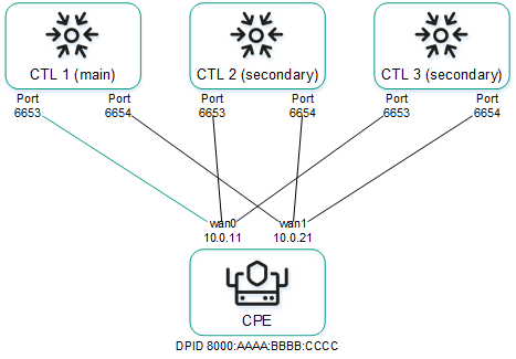
Management sessions between a CPE device and three controller nodes
Management sessions can be configured while configuring the connection of the CPE device to the orchestrator and controller. For example, you can select an SD-WAN interface of the WAN type to prioritize it for the purposes of establishing the primary management session; you can also enable or disable encryption for management sessions.
You can change the IP addresses and TCP port numbers of the controller nodes while configuring the controller nodes of an SD-WAN instance. This automatically changes the IP addresses and TCP port numbers of controller nodes on all CPE devices that are added to the SD-WAN instance. If SD-WAN interfaces of the WAN type of the CPE device are connected to different networks, for example, the internet and a private MPLS network, you can change the IP addresses and TCP port numbers of controller nodes on individual SD-WAN interfaces of the WAN type when you create or edit SD-WAN interfaces of the WAN type. The IP addresses and TCP port numbers specified on the SD-WAN interface of the WAN type take precedence over the IP addresses and TCP port numbers specified when configuring the controller nodes of the SD-WAN instance.
To display the table of CPE devices with information about management sessions, go to the Infrastructure menu section, click Management → Configuration menu next to the controller, and go to the Switches section. Information about management sessions is displayed in the following table columns:
- Name is the name of the CPE device.
- ID is the sequence number of the CPE device. The CPE device with the lowest sequence number was the first to connect to the controller.
- Status is the status of the CPE device in relation to the controller:
- Active means the CPE device can be used to relay traffic.
- Inactive means the CPE device cannot be used to relay traffic.
- Connection is the status of the CPE device connection to the controller:
- Connected means management sessions are established between the CPE device and the controller nodes.
- Disconnected means no management sessions are established between the CPE device and the controller nodes.
- MAC is the MAC address of the CPE device.
- Interface are SD-WAN interfaces of the WAN type from which management sessions are established.
- Primary session is the SD-WAN interface of the WAN type from which the primary management session is established:
- Yes
- No
- IP is the IP address which the SD-WAN interface of the WAN type used to establish the management session.
- Port is the TCP port which the SD-WAN interface of the WAN type used to establish the management session.
- Created is the date and time when the CPE device was registered.
- Location is the address of the CPE device location.
- Latency (ms.) is the latency in milliseconds of the management session.
- Description is a brief description of the CPE device.
Default credentials of KESR CPE devices
All KESR CPE devices have the same default credentials:
- Name of the user account:
root - Password:
123-qwe
You must enter these credentials to connect to an unregistered KESR CPE device over SSH or to establish a console session with it. After registration, the default password of the CPE device is automatically changed. You can view the CPE device password in the orchestrator web interface.
Page top
Scenario: Automatic registration (ZTP) of a CPE device
New CPE devices must be automatically registered using an URL with basic settings. Registration does not require connecting to Kaspersky cloud services. To perform this scenario, you need an administrator device, such as a laptop.
The automatic CPE device registration scenario involves the following steps:
- Creating a CPE template
Create and configure a CPE template. For a description of CPE template tabs, see the Managing CPE templates section. You can use the created CPE template to configure other CPE devices.
- Adding a CPE device
Add a CPE device. When adding the CPE device, assign the created CPE template to it and select whether the CPE device must automatically turn on after registration. The added CPE device has the Waiting status. For a description of CPE device tabs, see the Managing CPE devices section.
- Two-factor authentication
If you want to register your CPE device securely, use two-factor authentication. This step is optional.
- Generating an URL with basic settings
- Automatically registering a CPE device
Do the following:
- Connect the administrator device to the LAN port of the CPE device.
The administrator device gets an IP address and the IP address of the default gateway via DHCP. The received IP address of the default gateway is the IP address of the CPE device.
- Use the generated basic settings URL of the CPE device on the administrator device in one of the following ways:
- In the address bar of the browser, enter the basic settings URL of the CPE device and press Enter.
- Open the HTML file that you saved when generating the basic settings URL of the CPE device.
- On the opened page, click the Apply configuration button.
The CPE device connects to the orchestrator and is matched with the added record in the orchestrator web interface; the CPE device is then registered automatically. A registered CPE device has the Registered status and is in the Enabled or Disabled state.
- Connect the administrator device to the LAN port of the CPE device.
- Enabling the CPE device
If, when adding the CPE device, you specified that it must not be enabled automatically, enable the CPE device. An enabled CPE device has the Registered status and is in the Enabled state. This step is optional.
- Enabling traffic encryption on the device (optional step)
If you need to use traffic encryption on the CPE device, enable it for the entire device or for a specific link.
Scenario: Deployment on the VMware virtualization platform and automatic registration (ZTP) of a vCPE device
You can deploy a vCPE device on the VMware virtualization platform using an OVF template and then automatically register the vCPE device using a URL with basic settings. Registration does not require connecting to Kaspersky cloud services.
The OVF template is the knaas-cpe_<firmware version>.release.<solution version number>.combined.adm64-legacy.vKESR-M1-esxi.tar.gz archive that you can find in the /cpe directory of the distribution kit; the archive includes the following files:
- vKESR.mf contains the SHA256 hash of the OVF template files.
- vKESR.nvram contains the BIOS state of the virtual machine.
- vKESR.ovf is the descriptor containing information about the settings of the virtual machine.
- vKESR.vmdk is the disk image of the virtual machine.
You need to download the OVF template and extract it on your local device before performing this scenario.
The scenario for the deployment on the VMware virtualization platform and automatic registration (ZTP) of a vCPE device involves the following steps:
- Creating a vCPE template
Create and configure a vCPE template. For a description of vCPE template tabs, see the Managing CPE templates section. You can use the created vCPE template to configure other vCPE devices.
- Adding a vCPE device
Add a vCPE device. When adding a vCPE device:
- Specify the created vCPE template.
- Select whether you want the vCPE device to be powered on automatically after registration.
- Specify a temporary DPID of the vCPE device, for example,
temporary DPID.
The added vCPE device has the Waiting status. For a description of vCPE device tabs, see the Managing CPE devices section.
- Two-factor authentication
If you want to register your vCPE device securely, use two-factor authentication. This step is optional.
- Generating an URL with basic settings
- Deploying a vCPE device on the VMware virtualization platform
In the web interface of the VMware virtualization platform, create a virtual machine for deploying the vCPE device. Make sure that the virtual machine you are creating satisfies the hardware and software requirements. When creating the virtual machine:
- Select how you want to create the virtual machine, using the OVF standard or an OVA file.
- When selecting VDMK files, specify the files of the OVF template extracted on the local device.
- When configuring advanced settings, specify the generated URL with basic settings.
For details about creating virtual machines, please refer to the official VMware documentation.
If the settings are applied successfully, the vCPE device connects to the orchestrator and is displayed in the orchestrator web interface with the Unknown status.
- Automatically registering a vCPE device
Change the temporary DPID that you specified when adding the vCPE device to the actual DPID of the vCPE device. The actual DPID of the vCPE device is the host name of the virtual machine on which the vCPE device is deployed. The host name of the virtual machine is displayed in the web interface of the VMware virtualization platform.
The vCPE device with Unknown status is matched to the added vCPE device with the Waiting status in the orchestrator web interface and is automatically registered. A registered vCPE device has the Registered status and is in the Enabled or Disabled state.
- Enabling the vCPE device
If, when adding the vCPE device, you specified that it must not be enabled automatically, enable the vCPE device. An enabled vCPE device has the Registered status and is in the Enabled state. This step is optional.
Scenario: Re-registering a CPE device
If you delete a CPE device, the basic settings are kept on it. Such a CPE device can be re-registered without using the basic settings URL. Registration does not require connecting to Kaspersky cloud services.
When re-registering a CPE device, you cannot use two-factor authentication. If you want to use two-factor authentication, automatically register the CPE device.
The CPE device re-registration scenario involves the following steps:
- Restoring the CPE device firmware to the initial condition
Restore the CPE device firmware to the initial condition:
- Connect to the CPE device over SSH. To connect over SSH, specify the IP address and enter the credentials of the CPE device.
- Run the following command:
firstboot && reboot
- Creating a CPE template
Create and configure a CPE template. For a description of CPE template tabs, see the Managing CPE templates section. You can use the created CPE template to configure other CPE devices.
- Connecting the CPE device to the orchestrator
Disconnect and reconnect the CPE device power cable to have the CPE device reset and connect to the orchestrator. If the connection is successful, the CPE device is displayed in the orchestrator web interface with the Unknown status.
- Manually registering a CPE device
Manually register the CPE device. When manually registering the CPE device, assign the created CPE template to it and select whether the CPE device must automatically turn on after registration. A registered device has the Registered status and is in the Enabled or Disabled state. For a description of CPE device tabs, see the Managing CPE devices section.
- Enabling the CPE device
If, when manually registering the CPE device, you specified that it must not be enabled automatically, turn on the CPE device. An enabled CPE device has the Registered status and is in the Enabled state. This step is optional.
Managing CPE templates
The table of CPE templates is displayed in the SD-WAN → CPE templates section. Information about CPE templates is displayed in the following columns of the table:
- ID is the ID of the CPE template.
- Name is the name of the CPE template.
- Usage indicates whether the CPE template is being used by CPE devices:
- Yes
- No
- Updated is the date and time when the CPE template settings were last modified.
- User is the name of the user which created the CPE template.
- Owner is the tenant to which the CPE template belongs.
The actions that you can perform with the table are described in the Managing solution component tables instructions.
CPE template settings are displayed on the following tabs:
- Information is the basic information about the CPE template. You can edit the name of the CPE template in the Name field.
- Multipathing are the path settings.
- Deactivation are settings for automatically removing and disabling the CPE device.
- Encryption are the traffic encryption settings.
- Scripts are scripts for additional configuration of the CPE device.
- The following tabs are displayed on the SD-WAN settings tab:
- Global settings contains the connection settings of a CPE device to the orchestrator and controller.
- Interfaces contains SD-WAN interfaces.
- Topology contains topology tags for building links between CPE devices.
- Network settings contains network interfaces.
- BGP settings is the BGP protocol for exchanging routes between CPE devices and external network devices. The following tabs are displayed on this tab:
- General settings contains the basic settings of the BGP protocol.
- Neighbors contains BGP peers.
- Peer groups contains BGP peer groups.
- VRF contains virtual routing and forwarding tables.
- OSPF covers the OSPF protocol for route exchange between CPE devices and external network devices. The following tabs are displayed on this tab:
- General settings contains basic settings of the OSPF protocol.
- OSPF areas contains OSPF areas.
- OSPF interface contains OSPF interfaces.
- Routing filters contains settings for filtering routes and traffic packets between CPE devices and external network devices. The following tabs are displayed on this tab:
- Access control lists contains access control lists (ACLs).
- Prefix lists contains prefix lists.
- Route maps contains route maps.
- BFD settings covers the BFD protocol for detecting routing failures between CPE devices and external network devices.
- Static routes contains static routes.
- Multicast contains settings for transmission of multicast traffic between CPE devices and external network devices using the PIM and IGMP protocols. The following tabs are displayed on this tab:
- General settings contains basic PIM settings.
- Interfaces contains multicast interfaces.
- VRRP covers the VRRP protocol for high availability of CPE devices. The following tabs are displayed on this tab:
- VRRP instances contains VRRP instances.
- VRRP instance groups contains VRRP instance groups.
- Monitoring contains CPE device monitoring settings.
- Transport services contains transport services.
- Log files contains logging settings.
- NTP contains NTP servers for time synchronization.
- VIM contains VIM settings. This tab is displayed only if the uCPE type is selected when creating the template.
Creating a CPE template
To create a CPE template:
- In the menu, go to the SD-WAN → CPE templates section.
A table of CPE templates is displayed.
- In the upper part of the page, click + CPE template.
- This opens a window; in that window, in the Name field, enter the name of the CPE template.
- In the Type drop-down list, select the CPE template type:
- CPE for a standard CPE device template. Default value.
- uCPE for a uCPE device template. uCPE devices include a hypervisor, which lets you deploy virtual network functions and VIMs.
- Click Create.
The CPE template is created and displayed in the table.
You need to configure the created CPE template. For a description of CPE template tabs, see the Managing CPE templates section.
Page top
Importing a CPE template
You can export a CPE template and then import it into another CPE template. CPE template settings are specified in accordance with the settings of the imported CPE template. During import, you can select the tabs that you want to leave unchanged. The CPE template into which you are importing another CPE template remains applied to CPE devices, but the settings of those CPE devices are not modified.
To import a CPE template:
- In the menu, go to the SD-WAN → CPE templates section.
A table of CPE templates is displayed.
- Click the CPE template that you want to export.
The settings area is displayed in the lower part of the page. You can expand the settings area to fill the entire page by clicking the expand icon
. By default, the Information tab is selected, which displays general information about the CPE template. - In the upper part of the settings area, under Actions, click Export.
A TAR.GZ archive with the following data is saved on your local device:
- A file with the description of the CPE template in XML format. The version of the template is indicated in the description.
- Script files.
- Files required to run scripts, such as SSL certificates
The archive does not contain information about CPE devices using the CPE template.
- Click the CPE template into which you want to import the CPE template.
The settings area is displayed in the lower part of the page. You can expand the settings area to fill the entire page by clicking the expand icon
. By default, the Information tab is selected, which displays general information about the CPE template. - In the upper part of the settings area, under Actions, click Import.
- This opens a window; in that window, clear the check boxes next to the CPE template tabs that you want to leave unchanged after import.
- In the File field, specify the path to the TAR.GZ archive.
- Click Import.
CPE template settings are modified in accordance with the settings of the imported CPE template.
Page top
Cloning a CPE template
You can clone a CPE template to create an identical CPE template with a different name.
To clone a CPE template:
- In the menu, go to the SD-WAN → CPE templates section.
A table of CPE templates is displayed.
- Click the CPE template that you want to clone.
The settings area is displayed in the lower part of the page. You can expand the settings area to fill the entire page by clicking the expand icon
. By default, the Information tab is selected, which displays general information about the CPE template. - In the upper part of the settings area, under Actions, click Clone.
- This opens a window; in that window, enter the name of the new CPE template.
- Click Clone.
A copy of the CPE template with the new name is created and displayed in the table.
Page top
Exporting orchestrator and controller connection settings and SD-WAN interfaces from a CPE template
To export orchestrator and controller connection settings and SD-WAN interfaces from a CPE template:
- In the menu, go to the SD-WAN → CPE templates section.
A table of CPE templates is displayed.
- Click the CPE template from which you want to export orchestrator and controller connection settings and SD-WAN interfaces.
The settings area is displayed in the lower part of the page. You can expand the settings area to fill the entire page by clicking the expand icon
. By default, the Information tab is selected, which displays general information about the CPE template. - In the upper part of the settings area, under Actions, click Export SD-WAN settings.
A JSON file named <Template name>sdwan-config is saved to your local device.
Exporting network interfaces from a CPE template
To export network interfaces from a CPE template:
- In the menu, go to the SD-WAN → CPE templates section.
A table of CPE templates is displayed.
- Click the CPE template from which you want to export network interfaces.
The settings area is displayed in the lower part of the page. You can expand the settings area to fill the entire page by clicking the expand icon
. By default, the Information tab is selected, which displays general information about the CPE template. - In the upper part of the settings area, under Actions, click Export network interfaces.
A file in JSON format with the name <Template name>-network-config is saved to your local device.
Viewing the usage of a CPE template
You can see which CPE devices are using the CPE template. If a CPE template is in use, it cannot be deleted.
To view CPE template usage:
- In the menu, go to the SD-WAN → CPE templates section.
A table of CPE templates is displayed.
- Click the CPE template for which you want to view usage information.
The settings area is displayed in the lower part of the page. You can expand the settings area to fill the entire page by clicking the expand icon
. By default, the Information tab is selected, which displays general information about the CPE template. - In the upper part of the settings area, under Actions, click Show associated CPEs.
The CPE section is displayed with a table of CPE devices that are using the CPE template.
Page top
Deleting a CPE template
You cannot delete a CPE template if it is being used by at least one CPE device. You need to look up the usage of the CPE template and make sure that it is not in use.
Deleted CPE templates cannot be restored.
To delete a CPE template:
- In the menu, go to the SD-WAN → CPE templates section.
A table of CPE templates is displayed.
- Click the CPE template that you want to delete.
The settings area is displayed in the lower part of the page. You can expand the settings area to fill the entire page by clicking the expand icon
. By default, the Information tab is selected, which displays general information about the CPE template. - In the upper part of the settings area, under Actions, click Delete.
- In the confirmation window, click Delete.
The CPE template is deleted and is no longer displayed in the table.
Page top
Managing CPE devices
The table of CPE devices is displayed in the SD-WAN → CPE section. Information about CPE devices is displayed in the following columns of the table:
- DPID is the DPID of the CPE device.
- S/N is the serial number of the CPE device.
- Model is the model of the CPE device.
- SW version is the firmware version of the CPE device. Outdated firmware is highlighted in orange.
- CPE template is the CPE template used by the CPE device.
- Name is the name of the CPE device.
- Role is the role of the CPE device:
- CPE
- Gateway
- Status is the status of the CPE device.
- Unknown means the CPE device is connected to the orchestrator but is not registered.
- Waiting means the CPE device has been added in the orchestrator web interface, but it is not connected to the orchestrator.
- Registering means the CPE device is being registered.
- Error means an error occurred while registering the CPE device.
- Registered means the CPE device has been registered successfully.
- Configuration means scripts are being run on the CPE device.
- State is the state of the CPE device:
- Enabled means the assigned CPE template has been applied to the CPE device on the orchestrator side. On the controller side, the CPE device can be used to relay traffic.
- Disabled (in the Waiting status) means the assigned CPE template has not been applied to the CPE device on the orchestrator side. On the controller side, the CPE device cannot be used to relay traffic.
- Disabled (in the Registered status) means the orchestrator does not respond to REST API requests from the CPE device. On the controller side, the transmission of traffic through links is blocked for the CPE device.
- Connection indicates whether the CPE device is connected to the controller:
- Connected
- Disconnected
- Topology tags contains topology tags that have been assigned to the CPE device.
- Fragmentation is the result of checking for fragmentation of traffic packets on the CPE device:
- Unsupported means the CPE device cannot transmit fragmented packets.
- Unknown means packet fragmentation cannot be checked on the CPE device.
- Supported means the device can transmit fragmented packets.
- Usage indicates whether the SD-WAN interfaces of the CPE device are being used by transport services:
- Yes
- No
- Transport tenant is the transport tenant to which the CPE device is added. The CPE device connects to the controller of the SD-WAN instance that is deployed for the transport tenant.
- Customer tenant is the customer tenant to which the CPE device is added. The customer tenant can manage the CPE device in its self-service portal.
- Location is the address of the CPE device.
- Management IP is the IP address assigned to the CPE device by the management subnet.
- Controllers are IP addresses and port number of controllers to which the CPE device is connected.
- Gateways are IP addresses and port numbers of gateways to which the CPE device is connected.
- Mobile network is the mobile network to which the CPE device is connected.
- Registered is the date and time when the CPE device was registered.
- Update is the date and time when the CPE device settings were last modified.
- User is the name of the user which created the CPE device.
The actions that you can perform with the table are described in the Managing solution component tables instructions.
CPE device settings are displayed on the following tabs:
- Configuration is the basic information about the CPE device. You can enter a brief description of the CPE device in the Description field and view the tasks being performed by the orchestrator in the Out-of-band management table.
- Monitoring are CPE device monitoring results.
- Problems are problems that occurred while the CPE device was operational. In case of any problems, a red exclamation mark is displayed next to the tab.
- Encryption are the traffic encryption settings.
- Service requests are service requests of the CPE device.
- Tags are tags for grouping CPE devices.
- Scripts are scripts for additional configuration of the CPE device.
- The following tabs are displayed on the SD-WAN settings tab:
- Global settings contains the connection settings of a CPE device to the orchestrator and controller.
- Interfaces contains SD-WAN interfaces.
- Topology contains topology tags for establishing links between CPE devices.
- Network settings contains network interfaces.
- Firewall settings are firewall settings.
- VRF contains virtual routing and forwarding tables.
- BGP settings is the BGP protocol for exchanging routes between CPE devices and external network devices. The following tabs are displayed on this tab:
- General settings contains the basic settings of the BGP protocol.
- Neighbors contains BGP peers.
- Peer groups contains BGP peer groups.
- OSPF covers the OSPF protocol for route exchange between CPE devices and external network devices. The following tabs are displayed on this tab:
- General settings contains basic settings of the OSPF protocol.
- OSPF areas contains OSPF areas.
- OSPF interface contains OSPF interfaces.
- Routing filters contains settings for filtering routes and traffic packets between CPE devices and external network devices. The following tabs are displayed on this tab:
- Access control lists contains access control lists (ACLs).
- Prefix lists contains prefix lists.
- Route maps contains route maps.
- BFD settings covers the BFD protocol for detecting routing failures between CPE devices and external network devices.
- Static routes contains static routes.
- Multicast contains settings for transmission of multicast traffic between CPE devices and external network devices using the PIM and IGMP protocols. The following tabs are displayed on this tab:
- General settings contains basic PIM settings.
- Interfaces contains multicast interfaces.
- VRRP covers the VRRP protocol for high availability of CPE devices. The following tabs are displayed on this tab:
- VRRP instances contains VRRP instances.
- VRRP instance groups contains VRRP instance groups.
- UNIs are UNIs on the CPE device.
- Modems are CPE device modem settings.
- Links contains link settings.
- Multipathing are the path settings.
- Activation are two-factor authentication settings of the CPE device.
- Deactivation are settings for automatically removing and disabling the CPE device.
- Log files contains logging settings.
- NetFlow contains basic NetFlow settings.
- NTP displays NTP servers used for time synchronization.
- Diagnostic information displays requests for CPE device diagnostic information.
- Utilities displays utilities for diagnosing CPE devices.
Adding a CPE device
You need to add a CPE device if you are automatically registering it (ZTP). When adding a CPE device, you must specify the DPID that will be used to match the added record with the CPE device that you will connect later. You can add a CPE device to the current SD-WAN instance, a tenant, or a different SD-WAN instance.
To add a CPE device:
- Add a CPE device in one of the following ways:
- If you want to add a CPE device to the current SD-WAN instance, in the menu, go to the SD-WAN → CPE section and in the upper part of the page, click + CPE.
- If you want to add a CPE device to a tenant, in the menu, go to the Tenants section, under Tenants, select the created tenant, and under CPEs, click + CPE.
- If you want to add a CPE device to a different SD-WAN instance, navigate to the SD-WAN → SD-WAN instances subsection, click a deployed SD-WAN instance, and in the upper part of the settings area, under Actions, click Create.
- This opens a window; in that window, in the Name field, enter the name of the CPE device.
- In the DPID field, enter the DPID of the CPE device. You can find the DPID on the box of the CPE device.
If the CPE device does not have a DPID, you can specify a temporary DPID, for example,
temporary DPID. You can replace the temporary DPID with the actual DPID. - In the State drop-down list, select the CPE device state after registration:
- Enabled to apply a CPE template to the CPE device and use it to relay traffic. Default value.
- Disabled to not apply a CPE template to the CPE device.
- If necessary, in the Description field, enter a brief description of the CPE device.
- If you are adding a CPE device to an SD-WAN instance, in the Tenant drop-down list, select the transport tenant to which you want to add the CPE device. The CPE device connects to the controller of the SD-WAN instance that is deployed for the transport tenant. You can select an SD-WAN instance pool.
- In the Customer tenant drop-down list, select the customer tenant to which you want to add the CPE device. The customer tenant can manage the CPE device in its self-service portal.
- If you want to create a UNI on the CPE device using a UNI template, in the UNI template drop-down list, select the created UNI template.
- In the CPE template drop-down list, select the created CPE template which you want to use to configure the CPE device.
- In the NetFlow template drop-down list, select the created NetFlow template that you want to use to configure basic NetFlow settings on the CPE device.
- In the Firewall template drop-down list, select the created firewall template which you want to use to configure the firewall of the CPE device.
- Click Next and specify the address of the CPE device location in the Address field. As you enter the address, you are prompted to select an address from a drop-down list.
The address is displayed on the map.
- Click Add.
The device is added, its status changes to Waiting, and you get one of the following results:
- If you added the CPE device to the current SD-WAN instance, the CPE device is displayed in the table.
- If you added the CPE device to a tenant, the CPE device is displayed under CPEs.
- If you added the CPE device to a different SD-WAN instance, the self-service portal is opened in a new browser tab. You are automatically logged in to the self-service portal and taken to the CPE subsection. The CPE device is added to the table.
Generating an URL with basic CPE device settings
If you are automatically registering a CPE device, you need to generate a URL with basic CPE device settings. You can specify the template of the generated URL when configuring the connection of the CPE device to the orchestrator and controller. The generated URL contains the following information:
- Network interfaces
- Settings for connecting the CPE device to the orchestrator and controller and SD-WAN interfaces.
- Certificates
- BGP settings
- The token if two-factor authentication is being used
- Virtual routing and forwarding tables.
The maximum size of a URL with basic CPE device settings may not exceed 64 KB.
To generate a URL with basic CPE device settings:
- In the menu, go to the SD-WAN → CPE section.
A table of CPE devices is displayed.
- Click the CPE device for which you want to generate a URL with basic settings.
The settings area is displayed in the lower part of the page. You can expand the settings area to fill the entire page by clicking the expand icon
. By default, the Configuration tab is selected, which displays general information about the CPE device. This tab also displays the table of Out-of-band management tasks being performed by the orchestrator. - In the upper part of the settings area, under Actions, click Get activation URL.
This opens a window with the basic CPE device settings URL.
- Save the URL with basic CPE device settings in one of the following ways:
- If you want to copy the URL, click Copy next to it.
- If you want to save the URL as an HTML file, click Save to HTML next to it.
You need to connect an administrator device to the LAN port of the CPE device and use the saved URL with basic settings to automatically register the CPE device.
- If you want to install certificates on a CPE device with firmware version 23.07:
- In the Version drop-down list, select 23.07.
- Click Copy next to all generated URLs with basic settings.
- Save the generated URLs with basic settings.
You need to visit each of the copied URLs with basic settings in sequence on the CPE device where you want to install certificates.
Manually registering a CPE device
You must manually register the CPE device in the web interface when re-registering the CPE device. Registration does not require connecting to Kaspersky cloud services.
To manually register a CPE device:
- In the menu, go to the SD-WAN → CPE section.
A table of CPE devices is displayed.
- Click the CPE device that you want to manually register.
The settings area is displayed in the lower part of the page. You can expand the settings area to fill the entire page by clicking the expand icon
. By default, the Configuration tab is selected, which displays general information about the CPE device. This tab also displays the table of Out-of-band management tasks being performed by the orchestrator. - In the upper part of the settings area, under Actions, click Register.
- This opens a window; in that window, in the State drop-down list, select the CPE device state after registration:
- Enabled to apply a CPE template to the CPE device and use it to relay traffic. Default value.
- Disabled to not apply a CPE template to the CPE device.
- If necessary, in the Description field, enter a brief description of the CPE device.
- In the Tenant drop-down list, select the transport tenant to which you want to add the CPE device. The CPE device connects to the controller of the SD-WAN instance that is deployed for the transport tenant. You can select an SD-WAN instance pool.
- In the Customer tenant drop-down list, select the customer tenant to which you want to add the CPE device. The customer tenant can manage the CPE device in its self-service portal.
- If you want to create a UNI on the CPE device using a UNI template, in the UNI template drop-down list, select the created UNI template.
- In the CPE template drop-down list, select the created CPE template which you want to use to configure the CPE device.
- In the NetFlow template drop-down list, select the created NetFlow template that you want to use to configure basic NetFlow settings on the CPE device.
- In the Firewall template drop-down list, select the created firewall template which you want to use to configure the firewall of the CPE device.
- Click Next and specify the address of the CPE device location in the Address field. As you enter the address, you are prompted to select an address from a drop-down list.
The address is displayed on the map.
- Click Register.
The CPE device status changes first to Registering, then to Registered.
Page top
Unregistering a CPE device
To unregister a CPE device:
- In the menu, go to the SD-WAN → CPE section.
A table of CPE devices is displayed.
- Click the CPE device that you want to unregister.
The settings area is displayed in the lower part of the page. You can expand the settings area to fill the entire page by clicking the expand icon
. By default, the Configuration tab is selected, which displays general information about the CPE device. This tab also displays the table of Out-of-band management tasks being performed by the orchestrator. - In the upper part of the settings area, under Actions, click Unregister.
- In the confirmation window, click Unregister.
The CPE device is unregistered and the CPE device status changes to Waiting.
Page top
Specifying the address of a CPE device
To specify the address of a CPE device:
- In the menu, go to the SD-WAN → CPE section.
A table of CPE devices is displayed.
- Click the CPE device whose address you want to specify.
The settings area is displayed in the lower part of the page. You can expand the settings area to fill the entire page by clicking the expand icon
. By default, the Configuration tab is selected, which displays general information about the CPE device. This tab also displays the table of Out-of-band management tasks being performed by the orchestrator. - In the upper part of the settings area, under Actions, click Set location.
- This opens a window; in that window, enter the address of the CPE device's location. As you enter the address, you are prompted to select an address from a drop-down list.
The address is displayed on the map.
- Click Save.
The address of the CPE device is specified.
Page top
Enabling and disabling a CPE device
When a CPE device is enabled, a CPE template is applied to it. Disabled CPE devices cannot be used to relay traffic.
To enable or disable a CPE device:
- In the menu, go to the SD-WAN → CPE section.
A table of CPE devices is displayed.
- Click the CPE device that you want to enable or disable.
The settings area is displayed in the lower part of the page. You can expand the settings area to fill the entire page by clicking the expand icon
. By default, the Configuration tab is selected, which displays general information about the CPE device. This tab also displays the table of Out-of-band management tasks being performed by the orchestrator. - In the upper part of the settings area, under Actions, click Activate or Deactivate.
The CPE device is enabled or disabled.
Restarting a CPE device
To restart a CPE device:
- In the menu, go to the SD-WAN → CPE section.
A table of CPE devices is displayed.
- Click the CPE device that you want to restart.
The settings area is displayed in the lower part of the page. You can expand the settings area to fill the entire page by clicking the expand icon
. By default, the Configuration tab is selected, which displays general information about the CPE device. This tab also displays the table of Out-of-band management tasks being performed by the orchestrator. - In the upper part of the settings area, under Actions, click Reboot.
- In the confirmation window, click Reboot.
The CPE device is restarted.
Page top
Shutting down a CPE device
You can power off the CPE device in the orchestrator web interface, or by disconnecting the power cable from the CPE device. When the power is turned off in the orchestrator web interface, the shutdown command is sent to the operating system of the CPE device.
To power off the CPE device in the orchestrator web interface:
- In the menu, go to the SD-WAN → CPE section.
A table of CPE devices is displayed.
- Click the CPE device that you want to shut down.
The settings area is displayed in the lower part of the page. You can expand the settings area to fill the entire page by clicking the expand icon
. By default, the Configuration tab is selected, which displays general information about the CPE device. This tab also displays the table of Out-of-band management tasks being performed by the orchestrator. - In the upper part of the settings area, under Actions, click Shutdown.
- In the confirmation window, click Shutdown.
The CPE device is shut down.
Page top
Connecting to the CPE device console
To connect to the console of a CPE device:
- In the menu, go to the SD-WAN → CPE section.
A table of CPE devices is displayed.
- Click the CPE device to whose console you want to connect.
The settings area is displayed in the lower part of the page. You can expand the settings area to fill the entire page by clicking the expand icon
. By default, the Configuration tab is selected, which displays general information about the CPE device. This tab also displays the table of Out-of-band management tasks being performed by the orchestrator. - In the upper part of the settings area, under Actions, click Open SSH console.
This opens the CPE device console window in a new browser tab.
Page top
Viewing the password of a CPE device
To view the password of a CPE device:
- In the menu, go to the SD-WAN → CPE section.
A table of CPE devices is displayed.
- Click the CPE device whose password you want to view.
The settings area is displayed in the lower part of the page. You can expand the settings area to fill the entire page by clicking the expand icon
. By default, the Configuration tab is selected, which displays general information about the CPE device. This tab also displays the table of Out-of-band management tasks being performed by the orchestrator. - In the upper part of the settings area, under Actions, click Show password.
This opens a window with the CPE device password.
Page top
Exporting orchestrator and controller connection settings and SD-WAN interfaces from a CPE device
To export orchestrator and controller connection settings and SD-WAN interfaces from a CPE device:
- In the menu, go to the SD-WAN → CPE section.
A table of CPE devices is displayed.
- Click the CPE device from which you want to export orchestrator and controller connection settings and SD-WAN interfaces.
The settings area is displayed in the lower part of the page. You can expand the settings area to fill the entire page by clicking the expand icon
. By default, the Configuration tab is selected, which displays general information about the CPE device. This tab also displays the table of Out-of-band management tasks being performed by the orchestrator. - In the upper part of the settings area, under Actions, click Export SD-WAN settings.
A JSON file named <Template name>sdwan-config is saved to your local device.
Exporting network interfaces from a CPE device
To export network interfaces from a CPE device:
- In the menu, go to the SD-WAN → CPE section.
A table of CPE devices is displayed.
- Click the CPE device from which you want to export network interfaces.
The settings area is displayed in the lower part of the page. You can expand the settings area to fill the entire page by clicking the expand icon
. By default, the Configuration tab is selected, which displays general information about the CPE device. This tab also displays the table of Out-of-band management tasks being performed by the orchestrator. - In the upper part, under Actions click Export network interfaces.
A file in JSON format with the name <Template name>-network-config is saved to your local device.
Changing the DPID of a CPE device
You need to change the DPID when deploying a vCPE device on the VMware virtualization platform and automatically registering it.
To change the DPID of a CPE device:
- In the menu, go to the SD-WAN → CPE section.
A table of CPE devices is displayed.
- Click the CPE device whose DPID you want to change.
The settings area is displayed in the lower part of the page. You can expand the settings area to fill the entire page by clicking the expand icon
. By default, the Configuration tab is selected, which displays general information about the CPE device. This tab also displays the table of Out-of-band management tasks being performed by the orchestrator. - In the upper part of the settings area, under Actions, click Change DPID.
- This opens a window; in that window, enter the new DPID of the CPE device.
- Click Save.
The DPID of the CPE device is changed.
Page top
Deleting CPE devices
When you delete a CPE device, all service interfaces created on it are automatically deleted.
Deleted CPE devices cannot be restored.
To delete CPE devices:
- In the menu, go to the SD-WAN → CPE section.
A table of CPE devices is displayed.
- To delete an individual CPE device:
- Click the CPE device that you want to delete.
The settings area is displayed in the lower part of the page. You can expand the settings area to fill the entire page by clicking the expand icon
. By default, the Configuration tab is selected, which displays general information about the CPE device. This tab also displays the table of Out-of-band management tasks being performed by the orchestrator. - In the upper part of the settings area, under Actions, click Delete.
- Click the CPE device that you want to delete.
- To delete multiple CPE devices:
- Select check boxes next to the CPE devices that you want to delete.
- In the upper part of the table, click Actions → Delete.
- In the confirmation window, click Delete.
The CPE devices are deleted and are no longer displayed in the table.
Page top
Two-factor authentication of a CPE device
You can use two-factor authentication to register the CPE device securely. Two-factor authentication records a token (security key) to the orchestrator database; the token is then placed on the CPE device using the URL with basic settings. Registration succeeds if, when the CPE device connects to the orchestrator, the token placed on the device matches the CPE token in the orchestrator database.
To use two-factor authentication for a CPE device:
- In the menu, go to the SD-WAN → CPE section.
A table of CPE devices is displayed.
- Click the CPE device for which you want to use two-factor authentication.
The settings area is displayed in the lower part of the page. You can expand the settings area to fill the entire page by clicking the expand icon
. By default, the Configuration tab is selected, which displays general information about the CPE device. This tab also displays the table of Out-of-band management tasks being performed by the orchestrator. - Select the Activation tab.
Two-factor authentication settings are displayed.
- In the Two-factor authentication drop-down list, select Enabled. The default value is Disabled.
- If you want to generate a new token, click Generate under the Token field.
- In the upper part of the settings area, click Save to save CPE device settings.
Managing certificates
When communicating with the orchestrator, the CPE device checks whether the orchestrator's certificates can be trusted to prevent MITM attacks. By default, the CPE device trusts public certification authorities.
If the orchestrator uses certificates signed by a custom certification authority, you must upload these certificates in the orchestrator web interface and install them on CPE devices. Standalone root certificates as well as certificate chains consisting of a root certificate and multiple intermediate certificates are supported.
30 days before the certificate expires, a notification is displayed when you log into the orchestrator web interface.
The table of certificates is displayed under SD-WAN → Certificates. Information about certificates is displayed in the following columns of the table:
- Common name is the domain name or host name for which the certificate is issued.
- Organization is the name of the organization that issued the certificate.
- Distribute to CPEs is the check box for installing the certificate on CPE devices. Certificates that have their check boxes selected are installed on CPE devices in the following cases:
- Automatic registration (ZTP) of a CPE device
- CPE device restart
- Manual installation of certificates on the CPE device
Selecting certificates incorrectly may cause the CPE device to stop trusting the certificate of the orchestrator and to disconnect from it.
- From is the start date of certificate validity.
- To is the certificate expiration date.
The actions you can perform with the table are described in the Managing solution component tables instructions.
Uploading a certificate using the orchestrator web interface
To upload a certificate in the orchestrator web interface:
- In the menu, go to the SD-WAN → Certificates section.
A table of certificates is displayed.
- In the upper part of the page, click + Certificate.
- Specify the path to the certificate file in PEM format. Maximum file size: 16 KB.
The certificate is uploaded and displayed in the table. The Certificate <certificate name> uploaded message appears.
Page top
Manually installing certificates on CPE devices
To install certificates on CPE devices:
- In the menu, go to the SD-WAN → Certificates section.
A table of certificates is displayed.
- Select the Distribute to CPEs check boxes next to the uploaded certificates that you want to install on CPE devices.
- Click Apply to CPEs.
The certificates are installed on the CPE devices. The Certificates are applied to CPEs message is displayed.
Page top
Scenario: installing certificates on a CPE device with firmware version 23.07
You can install a root certificate or a certificate chain signed by a custom certification authority on a CPE device with firmware version 23.07. Firmware version 23.07 is not fully supported by the current version of the orchestrator, therefore technical issues may occur when using this firmware version. We recommend updating the firmware of all CPE devices to the latest version.
The scenario for installing certificates on CPE devices with firmware version 23.07 involves the following steps:
- Uploading certificates using the orchestrator web interface
- Generating an URL with basic CPE device settings
Generate a URL with basic CPE device settings while doing the following:
- In the Version drop-down list, select 23.07.
- Click Copy next to all generated URLs.
- Save the copied web addresses.
- Installing certificates on a CPE device
Visit each of the copied web address in sequence on the CPE device where you want to install certificates.
The CPE device restarts after installing each certificate.
Exporting a certificate
To export a certificate:
- In the menu, go to the SD-WAN → Certificates section.
A table of certificates is displayed.
- Click the certificate that you want to export.
The settings area is displayed in the lower part of the page. You can expand the settings area to fill the entire page by clicking the expand icon
. - In the upper part of the settings area, under Actions, click Export.
An certificate file in the PEM format is saved on your local device.
Page top
Deleting certificates
Deleted certificates cannot be restored.
To delete certificates:
- In the menu, go to the SD-WAN → Certificates section.
A table of certificates is displayed.
- To delete an individual certificate:
- Click the certificate that you want to delete
The settings area is displayed in the lower part of the page. You can expand the settings area to fill the entire page by clicking the expand icon
. - In the upper part of the settings area, under Actions, click Delete.
- Click the certificate that you want to delete
- To delete multiple certificates:
- Select check boxes next to certificates that you want to delete.
- In the upper part of the table, click Actions → Delete.
- In the confirmation window, click Delete.
The certificates are deleted and are no longer displayed in the table.
Page top
Automatically deleting and disabling CPE devices
In the CPE template or on the CPE device, you can specify the time after which the CPE device is deleted or disabled if the management session with the controller is terminated. Both functions are used to prevent theft of CPE devices. The automatic deletion function is also used to clean up obsolete entries from the orchestrator web interface. Both functions are disabled by default.
The automatic deletion or disabling time specified in a CPE template is automatically applied to all CPE devices that use this CPE template.
To configure automatic deletion and disabling of CPE devices:
- Proceed to configure automatic deletion and disabling in one of the following ways:
- If you want to configure automatic deletion and disabling in a CPE template, go to the SD-WAN → CPE templates menu section, click the CPE template and select the Deactivation tab.
- If you want to configure automatic deletion and disabling on a CPE device, go to the SD-WAN → CPE menu section, click the CPE device, and select the Deactivation tab and select the Override check boxes.
The automatic deletion and disabling settings of the CPE device are displayed.
- Enable automatic deletion of the CPE device:
- Select the Enable check box next to the Delete timeout (sec.) field.
- In the Delete timeout (sec.) field, enter the time in seconds after which the CPE device is deleted if communication with the controller is not possible. Range of values: 60 to 31,536,000. The entered value may not be lower than the value specified for the automatic disabling.
- Enable automatic disabling of the CPE device:
- Select the Enable check box next to the Deactivation timeout (sec.) field.
- In the Deactivation timeout (sec.) field, enter the time in seconds after which the CPE device is disabled if communication with the controller is not possible. Range of values: 60 to 31,536,000. The entered value may not be greater than the value specified for the automatic deletion.
- In the upper part of the settings area, click Save to save the settings of the CPE template or CPE device.
Grouping CPE devices using tags
Tags describe CPE device settings such as model, firmware version, and location address. When you add a CPE device, tags are automatically assigned to it, describing its model and tenant to which the CPE device was added.
You can use tags to group CPE devices and perform actions on groups. For example, you can assign the same tag to CPE devices located at the same location and then update firmware on them all.
To have a tag assigned, the CPE device must have the Registered status. Two identical tags cannot be assigned to the same CPE device.
Assigning a tag to CPE devices
To assign a tag to CPE devices:
- In the menu, go to the SD-WAN → CPE section.
A table of CPE devices is displayed.
- To assign a tag to an individual CPE device:
- Click the CPE device to which you want to assign a tag.
The settings area is displayed in the lower part of the page. You can expand the settings area to fill the entire page by clicking the expand icon
. By default, the Configuration tab is selected, which displays general information about the CPE device. This tab also displays the table of Out-of-band management tasks being performed by the orchestrator. - Select the Tags tab.
The assigned tags are displayed.
- Enter the tag and click the assign icon .
- In the upper part of the settings area, click Save to save CPE device settings.
- Click the CPE device to which you want to assign a tag.
- To assign a tag to multiple CPE devices:
- Select check boxes next to the CPE devices to which you want to assign a tag.
- In the upper part of the table, click Actions → Add tags.
- This opens a window; in that window, enter the tag and click the assign icon .
- Click Add.
The tag is assigned to the CPE devices.
Page top
Removing a CPE device tag
To remove a tag from CPE devices:
- In the menu, go to the SD-WAN → CPE section.
A table of CPE devices is displayed.
- To remove a tag from an individual CPE device:
- Click the CPE device from which you want to remove a tag.
The settings area is displayed in the lower part of the page. You can expand the settings area to fill the entire page by clicking the expand icon
. By default, the Configuration tab is selected, which displays general information about the CPE device. This tab also displays the table of Out-of-band management tasks being performed by the orchestrator. - Select the Tags tab.
The assigned tags are displayed.
- Click the remove icon next to the tag you want to remove.
- In the upper part of the settings area, click Save to save CPE device settings.
- Click the CPE device from which you want to remove a tag.
- To remove a tag from multiple CPE devices:
- Select check boxes next to the CPE devices from which you want to remove a tag.
- In the upper part of the table, click Actions → Delete tags.
- This opens a window; in that window, remove the tags in one of the following ways:
- Click the remove icon next to the tag you want to remove.
- Enter the tag you want to remove and select it from the drop-down list.
- Click the remove icon
- Click Delete.
The CPE device tag is removed.
Page top
Configuring logs on CPE devices
Logs generated on CPE devices are stored locally or sent to an external Syslog server. When storing logs locally, you can specify a maximum size. You can specify a prefix to be assigned to logs before they are sent to the external Syslog server.
To view the local log on the CPE device, you need to request diagnostic information.
You can specify log settings in a CPE template or on the CPE device. Log settings specified in the CPE template are automatically propagated to all CPE devices that use this CPE template.
To configure logs on CPE devices:
- Configure logs in one of the following ways:
- If you want to configure logs in a CPE template, go to the SD-WAN → CPE templates menu section, click the CPE template, and select the Log files tab.
- If you want to configure logs on a CPE device, go to the SD-WAN → CPE menu section, click the CPE device, select the Log files tab, and select the Override check box.
The log settings are displayed.
- In the Log files size (KB) field, enter the size of the logs on the CPE device in kilobytes. Range of values: 64 to 2048. Default value:
64. If the maximum log size is exceeded, new logs overwrite the oldest logs. - If you want the CPE device to send logs to an external Syslog server, specify the Syslog server:
- In the Syslog server IP/FQDN field, enter the IP address of the Syslog server.
- In the Syslog server port field, enter the port number of the Syslog server. Range of values: 0 to 65,353.
- In the Syslog server protocol drop-down list, select the protocol for sending logs to the Syslog server:
- UDP Default value.
- TCP
- In the Log files prefix field, enter the prefix that the CPE device assigns to the logs. Maximum length: 256 characters.
- In the upper part of the settings area, click Save to save the settings of the CPE template or CPE device.
Specifying NTP servers on CPE devices
You must specify an internal or external NTP server, or a pool of servers for CPE devices to make sure accurate time is displayed on these CPE devices. If you need to display accurate time on network devices that are connected to a CPE device, you can use such a CPE device as an NTP server.
You can specify the NTP server in a CPE template or on the CPE device. NTP servers specified in the CPE template are automatically specified on all CPE devices that use this CPE template.
To specify the NTP server on CPE devices:
- Specify the NTP server in one of the following ways:
- If you want to specify the NTP server in a CPE template, go to the SD-WAN → CPE templates section, click the CPE template, and select the NTP tab.
- If you want to specify an NTP server on a CPE device, go to the SD-WAN → CPE menu section, click the CPE device, and select the NTP tab and select the Override check box.
The NTP server connection settings are displayed.
- If you do not want to specify the NTP server for the CPE device, clear the Connect to NTP server check box. This check box is selected by default.
- If you want to use the CPE device as an NTP server, select the Use CPE as NTP server check box. This check box is cleared by default.
- Specify an NTP server or a pool of servers:
- Under NTP servers, click + Add.
- In the displayed field, enter the IP address or FQDN of the NTP server or pool of servers. The following IP address and FQDN formats are supported:
- To specify an NTP server, enter the IP address or FQDN in the
server<IP address or FQDN> format, for example,server 0.pool.ntp.org. - To specify a pool of NTP servers, enter the IP address or FQDN in the
pool<IP address or FQDN> format, for example,pool pool.ntp.org.
- To specify an NTP server, enter the IP address or FQDN in the
The NTP server is specified and displayed in the NTP servers section. You can specify multiple NTP servers or delete a NTP server. To delete an NTP server, click the delete icon
next to it. - In the upper part of the settings area, click Save to save the settings of the CPE template or CPE device.
You can request diagnostic information to view the time synchronization settings on a CPE device.
Page top
Managing modems
A CPE device can have up to four modems for connecting to the cellular network. To display the table of modems, go to the SD-WAN → CPE section, click the CPE device, and select the Modems tab. Information about modems is displayed in the following columns of the table:
- Name is the name of the modem.
- IP is the IP address of the modem.
- Subnet is the subnet to which the modem is connected.
- Gateway is the gateway to which the modem is connected.
- DNS1, DNS2 are DNS servers used by the modem.
- Signal is the signal strength of the modem.
- Data format is the data transfer protocol of the modem.
- Registration is the registration status of the modem.
- Network is the network to which the modem is connected.
- Country is the country in which the modem is registered.
- PLMN MCC is the Mobile Country Code.
- PLMN MNC is the Mobile Network Code.
- Roaming indicates whether roaming is being used on the modem:
- Yes
- No
- HTTP check is the result of the modem using HTTP to check the availability of the Internet.
The actions that you can perform with the table are described in the Managing solution component tables instructions.
Page top
Updating firmware
New versions of CPE device software are distributed by Kaspersky in the form of firmware. You can download a TAR.GZ archive with the firmware from the the /cpe directory of the distribution kit. You can update the firmware on a CPE device in three ways:
- Manually updating the CPE device firmware without using the orchestrator web interface.
- Scheduling firmware updates on selected CPE devices. In this case, you upload the firmware to the orchestrator web interface, select the CPE devices on which you want to update the firmware, and then update the firmware. A firmware update scheduled task is automatically created in the task scheduler.
- Scheduling firmware updates on CPE devices with specific tags. In this case, you upload the firmware to the orchestrator web interface, assign tags to CPE devices on which you want to update the firmware, and then create a firmware update task in the task scheduler. When creating the scheduled task, you need to specify the tags you assigned to CPE devices.
The CPE device restarts during the firmware update process.
The table of the firmware uploaded to the web interface is displayed in the SD-WAN→Firmware section. Information about firmware is displayed in the following columns of the table:
- Version is the firmware version.
- Size (MB) is the size of the firmware archive in megabytes.
- SHA256 is the hash of the firmware.
- Architecture is the instruction set architecture (ISA) of the firmware.
- Release date is the firmware release date.
- Model is the model of CPE devices with which the firmware is compatible.
The actions you can perform with the table are described in the Managing solution component tables instructions.
Manually updating firmware on a CPE device
When following these steps, you are prompted to enter the CPE device credentials. After registration, the default password of the CPE device is automatically changed. You can view the CPE device password in the orchestrator web interface.
To manually update the firmware on a CPE device:
- Download the firmware archive from the /cpe directory of the distribution kit to the administrator device, for example, your laptop. If you do not know which firmware version you need to install on the CPE device, use the table of correspondence of CPE device models with firmware versions.
- Connect the administrator device to the LAN port of the CPE device.
The administrator device gets the IP address of the default gateway via DHCP. The received IP address of the default gateway is the IP address of the CPE device.
- Connect to the CPE device over SCP, for example using WinSCP. To connect over SCP, specify the IP address and enter the credentials of the CPE device.
- Place the firmware archive in the /tmp directory.
- Connect to the CPE device over SSH. To connect over SSH, specify the IP address and enter the credentials of the CPE device.
- Change to the /tmp directory:
cd /tmp/ - Update the firmware on the CPE device in one of the following ways:
- If you want to leave the CPE device settings unchanged after updating the firmware, run the following command:
sysupgrade knaas-<firmware archive name> - If you want to reset the CPE device to factory settings after updating the firmware, run the following command:
sysupgrade -n knaas-cpe<firmware archive name>
When a CPE device is reset to factory settings, it is disconnected from the orchestrator. To reconnect the CPE device to the orchestrator, you need to automatically register (ZTP) the CPE device.
- If you want to leave the CPE device settings unchanged after updating the firmware, run the following command:
The new firmware version is installed on the CPE device, then the CPE device is restarted. By default, the IP address of the CPE device is unchanged, and DHCP is enabled on LAN ports.
Uploading firmware to the orchestrator web interface
To upload firmware in the orchestrator web interface:
- Download the archive with the firmware from the /cpe directory of the distribution kit to your local device. If you do not know which firmware version you need to install on the CPE device, use the table of correspondence of CPE device models with firmware versions.
- In the menu, go to the SD-WAN → Firmware section.
A table of firmware is displayed.
- In the upper part of the page, click + Firmware.
- Enter the path to the archive with the firmware. When specifying a path, you can select multiple archives at the same time.
The firmware is uploaded and displayed in the table.
Page top
Scheduling firmware updates on selected CPE devices
To create a firmware update scheduled task on selected CPE devices:
- In the menu, go to the SD-WAN → CPE section.
A table of CPE devices is displayed.
- Select the check boxes next to the CPE devices on which you want to update the firmware. Obsolete firmware is highlighted in orange in the SW version column of the table of CPE devices. You can also find CPE devices with outdated firmware versions using the Need update filter in the upper part of the table.
- In the upper part of the table, click Actions → Update firmware.
- This opens a window; in that window, in the Name field, enter the name of the scheduled task.
- In the Version drop-down list, select the uploaded firmware. If you do not know which firmware version you need to install on the CPE device, use the table of correspondence of CPE device models with firmware versions.
- In the Completion date and time field, enter the date and time when you want to run the task. By default, the date and time specified is the date and time when you started creating the task.
- If you want to reset the CPE device to factory settings after updating the firmware, clear the Save configuration check box. If the check box is selected, your existing CPE device settings are not modified after a firmware update. This check box is selected by default.
When a CPE device is reset to factory settings, it is disconnected from the orchestrator. To reconnect the CPE device to the orchestrator, you need to automatically register (ZTP) the CPE device.
- The Force update check box lets you force the firmware update, even if the CPE's internal check shows that the new firmware is incompatible with the old one. This check box is cleared by default.
- Click Next.
Two tables of CPE devices are displayed. Firmware of CPE devices in the upper table is updated. Firmware of CPE devices in the lower table is not updated. Information about CPE devices is displayed in the following columns of the table:
- DPID is the DPID of the CPE device.
- Model is the model of the CPE device.
- Name is the name of the CPE device.
- SW version is the firmware version of the CPE device.
- Transport tenant is the transport tenant to which the CPE device is added. The CPE device connects to the controller of the SD-WAN instance that is deployed for the transport tenant.
- Reason is the reason why the firmware cannot be updated. This column is displayed only in the lower table.
If the upper table contains CPE devices on which you do not want to update the firmware, you can move these CPE devices to the lower table.
- Click Schedule.
The scheduled task for updating the firmware is created and displayed in the table of scheduled tasks. The status of the tasks is displayed in the Status column. If the firmware update task finishes successfully, its status changes to Done.
Page top
Scheduling firmware updates on CPE devices with specific tags
To create a firmware update scheduled task on CPE devices with specific tags:
- In the menu, go to the Scheduler section.
The table of scheduled tasks is displayed.
- In the upper part of the page, click + Delayed task.
- This opens a window; in that window, in the Type drop-down list, select Delayed firmware update.
- In the Name field, enter the name of the scheduled task.
- In the Version drop-down list, select the uploaded firmware. If you do not know which firmware version you need to install on the CPE device, use the table of correspondence of CPE device models with firmware versions.
- In the Completion date and time field, enter the date and time when you want to run the task. By default, the date and time specified is the date and time when you started creating the task.
- If you want to reset the CPE device to factory settings after updating the firmware, clear the Save configuration check box. If the check box is selected, your existing CPE device settings are not modified after a firmware update. This check box is selected by default.
When a CPE device is reset to factory settings, it is disconnected from the orchestrator. To reconnect the CPE device to the orchestrator, you need to automatically register (ZTP) the CPE device.
- The Force update check box lets you force the firmware update, even if the CPE's internal check shows that the new firmware is incompatible with the old one. This check box is cleared by default.
- In the Tags field, enter the tags assigned to CPE devices on which you want to update the firmware. Obsolete firmware is highlighted in orange in the SW version column of the table of CPE devices. You can also find CPE devices with outdated firmware versions using the Need update filter in the upper part of the table.
- Click Next.
Two tables of CPE devices are displayed. Firmware of CPE devices in the upper table is updated. Firmware of CPE devices in the lower table is not updated. Information about CPE devices is displayed in the following columns of the table:
- DPID is the DPID of the CPE device.
- Model is the model of the CPE device.
- Name is the name of the CPE device.
- SW version is the firmware version of the CPE device.
- Transport tenant is the transport tenant to which the CPE device is added. The CPE device connects to the controller of the SD-WAN instance that is deployed for the transport tenant.
- Reason is the reason why the firmware cannot be updated. This column is displayed only in the lower table.
If the upper table contains CPE devices on which you do not want to update the firmware, you can move these CPE devices to the lower table.
- Click Create.
The scheduled task for updating the firmware is created and displayed in the table. The status of the tasks is displayed in the Status column. If the firmware update task finishes successfully, its status changes to Done.
Restoring firmware of a KESR-M1 CPE device
You can restore the firmware and reset a KESR-M1 CPE device to factory settings if you have lost the credentials of that CPE or if you encounter a problem with the firmware.
When a CPE device is reset to factory settings, it is disconnected from the orchestrator. To reconnect the CPE device to the orchestrator, you need to automatically register (ZTP) the CPE device.
To restore the firmware of a KESR-M1 CPE device:
- Download the firmware archive from the /cpe directory of the distribution kit to the administrator device, for example, your laptop. If you do not know which firmware version you need to install on the CPE device, use the table of correspondence of CPE device models with firmware versions.
- Extract the firmware archive to get the firmware in BIN format.
- Power on the CPE device with factory firmware:
- Disconnect the power cable of the CPE device.
- Connect the power cable and press and hold the RESET button on the CPE device for 10 seconds.
The CPE device powers on with the factory firmware.
- Connect the administrator device to the LAN port of the CPE device.
The administrator device gets an IP address and the IP address of the default gateway in the 192.168.1.0/24 subnet via DHCP.
- In the address bar of the browser on the administrator device, enter
192.168.1.1and press Enter.This opens the CPE device firmware upload page.
- Click the firmware upload button and specify the path to the firmware in BIN format. You got the firmware in BIN format at step 2 of these instructions.
The new firmware version is installed on the CPE device, then the CPE device is restarted. By default, the IP address of the CPE device is 192.168.7.1, and DHCP is enabled on LAN ports.
Page top
Restoring firmware of a KESR-M2-5 CPE device
You can restore the firmware and reset a KESR-M2-5 CPE device to factory settings if you have lost the credentials of that CPE or if you encounter a problem with the firmware.
When a CPE device is reset to factory settings, it is disconnected from the orchestrator. To reconnect the CPE device to the orchestrator, you need to automatically register (ZTP) the CPE device.
To restore the firmware of a KESR-M2-5 CPE device:
- Download the firmware archive from the /cpe directory of the distribution kit to the administrator device, for example, your laptop. If you do not know which firmware version you need to install on the CPE device, use the table of correspondence of CPE device models with firmware versions.
- Extract the firmware archive to get an archive in IMG.GZ format.
- Unpack the IMG.GZ archive to get the firmware image in IMG format.
- Use the IMG firmware to create a bootable USB drive using disk image writing software such as BalenaEtcher.
- Connect the administrator device to the CPE device with a console cable and insert the USB drive into the USB port of the CPE device.
- Specify the settings for establishing a console session with the CPE device on the administrator device, for example, using the PuTTY application, and do the following:
- Specify the communications port (COM port) number of the administrator device.
- Specify
115200as the session speed.
- Disconnect and reconnect the power cable of the CPE device. Press F7 or F11 while the CPE device is powering on.
- This opens a menu; in the menu, select the USB drive and press Enter.
The CPE device boots from the USB drive.
- Connect the administrator device to the LAN port of the CPE device.
The administrator device gets an IP address and the IP address of the default gateway in the 192.168.7.0/24 subnet via DHCP.
- Connect to the CPE device over SCP, for example using WinSCP. To connect over SCP, specify the IP address and enter the default credentials of the CPE device.
- Place the firmware in IMG format in the /tmp directory.
- Connect to the CPE device over SSH or establish a console session with the CPE device. To connect over SSH or establish a console session, specify the IP address and enter the default credentials of the CPE device.
- Change to the /tmp directory:
cd /tmp/ - Copy the firmware image in IMG format to /dev/sda:
dd if=<name of the firmware IMG file> bs=1M of=/dev/sda - Restart the CPE device by running the following command:
reboot
The new firmware version is installed on the CPE device, then the CPE device is restarted. By default, the IP address of the CPE device is 192.168.7.1, and DHCP is enabled on LAN ports.
Page top
Correspondence of CPE device models with firmware versions
The table below shows the correspondence of CPE device models with the supported firmware versions.
Model of the CPE device |
Supported firmware version |
|---|---|
KESR M1 |
knaas-cpe_<firmware version>.release.<solution version number>.firmware.kesr-m1-r-5g-2l-w-v2_en-US_ru-RU.tar.gz |
KESR M2 (Wi-Fi/LTE) |
knaas-cpe_<firmware version>.release.<solution version number>.efi.amd64-kesr-m2-k-5g-1l-w_en-US_ru-RU.tar.gz |
KESR M2 (SFP) |
knaas-cpe_<firmware version>.release.<solution version number>.efi.amd64-kesr-m2-k-5g-1s _en-US_ru-RU.tar.gz |
KESR M3 |
knaas-cpe_<firmware version>.release.<solution version number>.efi.amd64-kesr-m3-k-4g-4s_en-US_ru-RU.tar.gz |
KESR M4 (SFPx2) |
knaas-cpe_<firmware version>.release.<solution version number>.efi.amd64-kesr-m4-k-2x-1cpu_en-US_ru-RU.tar.gz |
KESR M4 (SFPx4/RJ-45x8) |
knaas-cpe_<firmware version>.release.<solution version number>.efi.amd64-kesr-m4-k-8g-4x-1cpu_en-US_ru-RU.tar.gz |
KESR M5 (SFPx8) |
knaas-cpe_<firmware version>.release.<solution version number>.efi.amd64-kesr-m5-k-8x-2cpu_en-US_ru-RU.tar.gz |
KESR M5 (SFPx4/RJ-45x8) |
knaas-cpe_<firmware version>.release.<solution version number>.efi.amd64-kesr-m5-k-8g-4x-2cpu_en-US_ru-RU.tar.gz |
Deleting firmware
You cannot delete firmware that is being used in a scheduled task.
Deleted firmware cannot be restored.
To delete firmware:
- In the menu, go to the SD-WAN → Firmware section.
A table of firmware is displayed.
- Select check boxes next to firmware that you want to delete.
- In the upper part of the table, click Actions → Delete.
- In the confirmation window, click Delete.
The firmware is deleted and is no longer displayed in the table.
Page top
Additional configuration of CPE devices using scripts
You can use scripts for additional configuration of CPE devices. You can add scripts to a CPE template. Scripts added to the CPE template are automatically added to all CPE devices that use this CPE template. Added scripts can be run automatically or manually. Scripts are run automatically when the conditions specified in the script settings are satisfied, for example, when a CPE device is registered.
Running scripts is the responsibility of VNFM, so network connectivity between VNFM and CPE devices must be ensured before you begin working with scripts. By default, the port number for connecting the VNFM to the device and the user name for running scripts are specified in the CPE template. You can change the port number and user name if necessary.
The table of scripts is displayed in the CPE template and on the CPE device:
- To display the table of scripts in a CPE template, go to the SD-WAN → CPE templates menu section, click the CPE template, and select the Scripts tab.
- To display the table of scripts on a CPE device, go to the SD-WAN → CPE menu section, click the CPE device, and select the Scripts tab.
Information about scripts is displayed in the following columns of the table:
- Name is the script name.
- Executor is the interpreter.
- Authentication is the type of VNFM authentication in the CPE device.
- Custom executor is the path to the custom interpreter.
- Timeout (sec.) is the time in seconds after which the VNFM stops attempting to run a script that could not run the first time.
- Repeat execution indicates whether the script can be re-run:
- Yes
- No
- Stage is the stage of the CPE device operation at which VNFM runs the script.
- Script is name of the script file or the Ansible playbook file.
- File is the name of the archive with additional files that the script requires to run.
- Actions contains the actions that can be performed with the script.
Adding a script to CPE devices
You can add a script to a CPE template. Scripts added to the CPE template are automatically added to all CPE devices that use this CPE template.
To add a script to CPE devices:
- In the menu, go to the SD-WAN → CPE templates section.
A table of CPE templates is displayed.
- Click the CPE template to which you want to add a script.
The settings area is displayed in the lower part of the page. You can expand the settings area to fill the entire page by clicking the expand icon
. By default, the Information tab is selected, which displays general information about the CPE template. - Select the Scripts tab.
This displays the port number that VNFM uses to connect to the CPE device, the user name for running scripts, and the table of script if at least one script has been added.
- Click + Script.
- This opens a window; in that window, in the Name field, enter the name of the script. Maximum length: 255 characters.
- In the Timeout (sec.) field, enter the time in seconds after which the VNFM stops attempting to run a script that could not run the first time. Default value:
360. - In the Executor drop-down list, select one of the following values:
- Ansible. Default value.
- Shell
- Expect
- Custom to use an interpreter on the CPE device. If you s! this value is selected, enter the path to the interpreter in the Custom executor field.
- In the Stage drop-down list, select the stage of CPE device operation at which VNFM runs the script:
- Registration. Default value.
- Deletion
- Manually to run the script only manually.
- If you need to run the script again, select the Repeat execution check box. This check box is cleared by default. Consider the following special considerations for re-running a script:
- If in the Stage drop-down list, you selected Registration, the script is re-run in cases of registration, powering on, and restart of the CPE device.
- If in the Stage drop-down list, you selected Deletion, the script does not run again.
- If in the Stage drop-down list, you selected Manually, the script is re-run in cases of powering on and restart of the CPE device.
- In the Script field, enter the path to the script file or to the Ansible playbook script file.
- If necessary, in the File field, specify the path to the archive with additional files required to run the script. Supported formats of archives with files: TAR.GZ and ZIP.
- Click Save.
The script is created and displayed in the table.
- In the upper part of the settings area, click Save to save CPE template settings.
Manually running a script on CPE devices
You can manually run an individual script or all scripts in a CPE template or on a CPE device. Scripts started in a CPE template are automatically run on all CPE devices that use this CPE template or on CPE devices with specific tags.
Manually running scripts in a CPE template
To manually run scripts in a CPE template:
- In the menu, go to the SD-WAN → CPE templates section.
A table of CPE templates is displayed.
- Click the CPE template in which you want to manually run scripts.
The settings area is displayed in the lower part of the page. You can expand the settings area to fill the entire page by clicking the expand icon
. By default, the Information tab is selected, which displays general information about the CPE template. - Select the Scripts tab.
This displays the port number that VNFM uses to connect to the CPE device, the user name for running scripts, and the table of script if at least one script has been added.
- To manually run an individual script:
- Click Run next to the script that you want to run manually.
- This opens a window; in that window, select the CPE devices on which you want to run the script:
- Run the script <script name> on all related CPEs runs the script on all CPE devices that use the CPE template. Default value.
- Run <script name> on all related CPEs with specified tags runs the script on CPE devices that use the CPE template and have specific tags assigned. If you select this value, specify the tags in the lower part of the window.
- To manually run all scripts:
- In the upper part of the settings area, under Actions, click Run scripts.
- This opens a window; in that window, select the CPE devices on which you want to run the scripts:
- Run all scripts on related CPEs to run the scripts on all CPE devices that use the CPE template. Default value.
- Run all scripts on related CPEs with specified tags to run the scripts on CPE devices that use the CPE template and have specific tags assigned. If you select this value, specify the tags in the lower part of the window.
- Click Run.
The scripts are run.
Manually running scripts on a CPE device
To manually run scripts on a CPE device:
- In the menu, go to the SD-WAN → CPE section.
A table of CPE devices is displayed.
- Click the CPE device on which you want to manually run scripts.
The settings area is displayed in the lower part of the page. You can expand the settings area to fill the entire page by clicking the expand icon
. By default, the Configuration tab is selected, which displays general information about the CPE device. This tab also displays the table of Out-of-band management tasks being performed by the orchestrator. - Select the Scripts tab.
This displays the port number that VNFM uses to connect to the CPE device, the user name for running scripts, and the table of script if at least one script has been added.
- Manually run the scripts in one of the following ways:
- If you want to manually run an individual script, click Run next to the relevant script.
- If you want to manually run all scripts, in the upper part of the settings area, under Actions, click Run scripts.
- This opens a window; in that window, click Run.
The scripts are run.
Page top
Scheduling scripts on CPE devices
Scheduled tasks for running scripts on CPE devices can be created in the task scheduler. When creating a scheduled task, you must select a CPE template, scripts, and CPE devices on which you want to run the scripts.
You can run scripts on all CPE devices that use a CPE template, or constrain the number of CPE devices by specifying tags or manually selecting CPE devices.
To create a scheduled task to run scripts on CPE devices:
- In the menu, go to the Scheduler section.
The table of scheduled tasks is displayed.
- In the upper part of the page, click + Delayed task.
- This opens a window; in that window, in the Type drop-down list selectScript execution.
- In the Name field, enter the name of the scheduled task.
- In the CPEs to run script on drop-down list, select the CPE devices on which you want to run the script:
- Under CPE template, select the CPE template that contains the scripts that you want to run.
- Under Scripts, select the scripts that you want to run.
- In the Completion date and time field, enter the date and time when you want to run the scheduled task. By default, the date and time specified is the date and time when you started creating the scheduled task.
- Click Create.
A scheduled task for running the script is created and displayed in the table. The status of the scheduled tasks is displayed in the Status column. If the scheduled task to run a script finishes successfully, its status changes to Done.
Page top
Editing a script on CPE devices
You can edit a script in the CPE template. A script edited in the CPE template is automatically modified on all CPE devices that use this CPE template.
To edit a script on CPE devices:
- In the menu, go to the SD-WAN → CPE templates section.
A table of CPE templates is displayed.
- Click the CPE template in which you want to edit a script.
The settings area is displayed in the lower part of the page. You can expand the settings area to fill the entire page by clicking the expand icon
. By default, the Information tab is selected, which displays general information about the CPE template. - Select the Scripts tab.
This displays the port number that VNFM uses to connect to the CPE device, the user name for running scripts, and the table of script if at least one script has been added.
- Click Edit next to the script that you want to edit.
- This opens a window; in that window, if necessary, edit the script settings. For a description of the settings, see the instructions for adding a script on CPE devices.
- Click Save.
The script is modified and updated in the table.
- In the upper part of the settings area, click Save to save CPE template settings.
Deleting a script on CPE devices
You can delete a script in the CPE template. A script deleted in the CPE template is automatically deleted on all CPE devices that use this CPE template.
Deleted scripts cannot be restored.
To delete a script on CPE devices:
- In the menu, go to the SD-WAN → CPE templates subsection.
A table of CPE templates is displayed.
- Click the CPE template.
The settings area is displayed in the lower part of the page. You can expand the settings area to fill the entire page by clicking the expand icon
. By default, the Information tab is selected, which displays general information about the CPE template. - Select the Scripts tab.
This displays the port number that VNFM uses to connect to the CPE device, the user name for running scripts, and the table of script if at least one script has been added.
- Click Delete next to the script that you want to delete.
The script is deleted and is no longer displayed in the table.
- In the upper part of the settings area, click Save to save CPE template settings.
Managing network interfaces
Network interfaces correspond to ports and virtual interfaces of the CPE device's operating system that connect to the WAN or the LAN. You must map the network interfaces of the CPE device to the OpenFlow ports of the virtual switch using SD-WAN interfaces.
The table of network interfaces is displayed in the CPE template and on the CPE device:
- To display the table of network interfaces in a CPE template, go to the SD-WAN → CPE templates menu section, click the CPE template, and select the Network settings tab.
- To display the table of network interfaces on a CPE device, go to the SD-WAN → CPE menu section, click the CPE device, and select the Network settings tab.
Information about network interfaces is displayed in the following columns of the table:
- Alias is the name of the network interface for mapping the network interface to an OpenFlow port. You specify this name when creating an SD-WAN interface of the WAN type.
- Inherited indicates whether the network interface is inherited from CPE template:
- Yes
- No
This column is displayed only on the CPE device.
- Interface name is the name of the physical port or virtual interface of the operating system of the CPE device.
- Protocol is the method of assigning an IP address to the network interface:
- DHCP client means the IP address is automatically assigned by DHCP.
- Static IPv4 address means an IPv4 address is statically assigned.
- Static IPv6 address means an IPv6 address is statically assigned.
- QMI means LTE network connection settings are specified manually.
- PPPoE means the PPPoE server connection settings are specified manually.
- None means an IP address is not assigned.
- IP/mask are the IP address, mask, and default gateway of the network interface.
- Enable automatically indicates whether the network interface is automatically enabled when the CPE device is powered on:
Creating network interfaces
You can create a network interface in a CPE template or on a CPE device. A network interface created in the CPE template is automatically created on all CPE devices that use this CPE template.
Creating a network interface with automatic assignment of an IP address via DHCP
To create a network interface with automatic assignment of an IP address via DHCP:
- Create a network interface in one of the following ways:
- If you want to create a network interface in a CPE template, go to the SD-WAN → CPE templates section, click the CPE template, and select the Network settings tab.
- If you want to create a network interface on a CPE device, go to the SD-WAN → CPE section, click the CPE device, and select the Network settings tab.
The table of network interfaces is displayed.
- Click + Network interface.
- This opens a window; in that window, in the Alias field, enter the name of the network interface for mapping the network interface to an OpenFlow port. You must specify this alias when creating an SD-WAN interface of the WAN type. Maximum length: 15 characters.
- If you want to add a network interface to a firewall zone, in the Zone drop-down list, select the created firewall zone.
- In the Interface name field, enter the name of the physical port or virtual interface of the operating system of the CPE device. Maximum length: 256 characters. For example, you can enter
eth0,eth1,eth2, ortun0. To create a bridge from multiple interfaces, enter their names separated by spaces.If you want to assign an outer VLAN tag to a network interface, enter a period (.) after the physical port or virtual interface name of the operating system, and then enter the outer VLAN tag. For example, you can enter
eth2.150. - If you want to create a bridge from physical or virtual interfaces whose names are specified in the Interface name field:
- Select the Bridge check box. This check box is cleared by default.
- If you want to use STP on the bridge to prevent routing loops, select the STP check box. This check box is cleared by default.
- In the Age (sec.) field, enter the duration in seconds for which dynamic records are stored in the MAC table of the bridge. If you want to use the bridge as a hub, enter
0in this field. Range of values: 0 to 86,400.
- If you want to enable the NetFlow protocol on the network interface, select the NetFlow check box. This check box is cleared by default.
- In the Protocol drop-down list, select DHCP client.
- If you do not want the network interface to be automatically enabled when the the CPE device is enabled, clear the Enable automatically check box. This check box is selected by default.
- If you want an IP address, route, and default gateway automatically assigned to the network interface, select the Force IP, route, and gateway check box. This check box is cleared by default.
- If you do not want the route obtained via DHCP to be used by network interface by default, clear the Use default route check box. This check box is selected by default.
- If necessary, specify a DNS server for the network interface:
- Under DNS servers, click + Add.
- In the field that is displayed, enter the IP address of the DNS server.
The DNS server is specified and displayed in the DNS servers section. You can specify multiple DNS servers or delete a DNS server. To delete a DNS server, click the delete icon
next to it. - In the Override MAC field, enter the MAC address of the network interface. The entered value replaces the actual MAC address of the network interface.
- In the Override MTU field, enter the MTU for the network interface. The entered value overrides the default MTU.
- In the Route metric field, enter the default route metric for the network interface. The CPE device uses the default route with the lowest metric. For example, you can specify the following default route metrics for network interfaces:
100for network interface sdwan0101for network interface sdwan1102for network interface sdwan2
In this case, the CPE device uses the default route of the sdwan0 network interface. If the sdwan0 network interface fails, the default route of the sdwan1 network interface is used next, followed by the default route of the sdwan2 network interface.
- Click Create.
The network interface is created and displayed in the table.
- In the upper part of the settings area, click Save to save the settings of the CPE template or CPE device.
Creating a network interface with a static IPv4 address
To create a network interface with a static IPv4 address:
- Create a network interface in one of the following ways:
- If you want to create a network interface in a CPE template, go to the SD-WAN → CPE templates section, click the CPE template, and select the Network settings tab.
- If you want to create a network interface on a CPE device, go to the SD-WAN → CPE section, click the CPE device, and select the Network settings tab.
The table of network interfaces is displayed.
- Click + Network interface.
- This opens a window; in that window, in the Alias field, enter the name of the network interface for mapping the network interface to an OpenFlow port. You must specify this alias when creating an SD-WAN interface of the WAN type. Maximum length: 15 characters.
- If you want to add a network interface to a firewall zone, in the Zone drop-down list, select the created firewall zone.
- In the Interface name field, enter the name of the physical port or virtual interface of the operating system of the CPE device. Maximum length: 256 characters. For example, you can enter
eth0,eth1,eth2, ortun0. To create a bridge from multiple interfaces, enter their names separated by spaces.If you want to assign an outer VLAN tag to a network interface, enter a period (.) after the physical port or virtual interface name of the operating system, and then enter the outer VLAN tag. For example, you can enter
eth2.150. - If you want to create a bridge from physical or virtual interfaces whose names are specified in the Interface name field:
- Select the Bridge check box. This check box is cleared by default.
- If you want to use STP on the bridge to prevent routing loops, select the STP check box. This check box is cleared by default.
- In the Age (sec.) field, enter the duration in seconds for which dynamic records are stored in the MAC table of the bridge. If you want to use the bridge as a hub, enter
0in this field. Range of values: 0 to 86,400.
- If you want to enable the NetFlow protocol on the network interface, select the NetFlow check box. This check box is cleared by default.
- In the Protocol drop-down list, select Static IPv4 address.
- If you do not want the network interface to be automatically enabled when the CPE device is enabled, clear the Enable automatically check box. This check box is selected by default.
- If you want an IP address, route, and default gateway automatically assigned to the network interface, select the Force IP, route, and gateway check box. This check box is cleared by default.
- In the IPv4 address and subnet mask input type drop-down list, select the method for assigning an IPv4 address to the network interface:
- Manually to manually assign an IPv4 address. If you select this option, do the following:
- In the IPv4 address field, enter the IPv4 address of the network interface.
- In the IPv4 netmask field, enter the subnet mask of the network interface.
- From IP pool to assign an IPv4 address from the specified range of IP addresses. If you select this value, in the IP Pool drop-down list, select a created range of IP addresses.
- From subnet pool to assign an IPv4 address from the specified range of subnets. If you select this value, in the Subnet Pool drop-down list, select a created range of subnets.
- Manually to manually assign an IPv4 address. If you select this option, do the following:
- In the IPv4 gateway field, enter the IPv4 address of the default gateway.
- In the IPv4 broadcast field, enter the broadcast address of the network interface. If you do not specify a value for this setting, it is generated automatically.
- If necessary, specify a DNS server for the network interface:
- Under DNS servers, click + Add.
- In the field that is displayed, enter the IP address of the DNS server.
The DNS server is specified and displayed in the DNS servers section. You can specify multiple DNS servers or delete a DNS server. To delete a DNS server, click the delete icon
next to it. - In the Override MAC field, enter the MAC address of the network interface. The entered value replaces the actual MAC address of the network interface.
- In the Override MTU field, enter the MTU for the network interface. The entered value overrides the default MTU.
- In the Route metric field, enter the default route metric for the network interface. The CPE device uses the default route with the lowest metric. For example, you can specify the following default route metrics for network interfaces:
100for network interface sdwan0101for network interface sdwan1102for network interface sdwan2
In this case, the CPE device uses the default route of the sdwan0 network interface. If the sdwan0 network interface fails, the default route of the sdwan1 network interface is used next, followed by the default route of the sdwan2 network interface.
- Under DHCP server, in the Type drop-down list, select the operating mode of the DHCP server for the network interface:
- Disabled. Default value.
- Relay If you select this value, enter the IP address of the DHCP server in the DHCP server IP field.
- Server
- If the Type drop-down list, you selectedServer, specify the DHCP server settings:
- In the First IP field, enter the offset from the base IP address of the network interface for deriving the lowest IP address that can be leased to clients. Default value:
100. You can enter a value greater than 255 for large subnets. - In the Limit field, enter the maximum number of IP addresses that can be leased to clients. Range of values: 1 to 250. Default value:
150. - In the Lease time field, enter the maximum time, in hours, for which an individual IP address can be leased to a client. Range of values: 1 to 250. The value is specified in the following format:
<number of hours>h. For example, if you want the maximum lease time to be 5 hours, enter5h. The default value is12h. - If necessary, specify a DHCP option:
- Under DHCP options, click + Add.
- In the field that is displayed, enter the number of the DHCP option in accordance with the RFC 1533 standard. Maximum length: 250 characters.
The DHCP option is specified and displayed under DHCP options. You can specify multiple DHCP options or delete a DHCP option. To delete a DHCP option, click the delete icon
next to it.
- In the First IP field, enter the offset from the base IP address of the network interface for deriving the lowest IP address that can be leased to clients. Default value:
- Click Create.
The network interface is created and displayed in the table.
- In the upper part of the settings area, click Save to save the settings of the CPE template or CPE device.
Creating a network interface with a static IPv6 address
To create a network interface with a static IPv6 address:
- Create a network interface in one of the following ways:
- If you want to create a network interface in a CPE template, go to the SD-WAN → CPE templates section, click the CPE template, and select the Network settings tab.
- If you want to create a network interface on a CPE device, go to the SD-WAN → CPE section, click the CPE device, and select the Network settings tab.
The table of network interfaces is displayed.
- Click + Network interface.
- This opens a window; in that window, in the Alias field, enter the name of the network interface for mapping the network interface to an OpenFlow port. You must specify this alias when creating an SD-WAN interface of the WAN type. Maximum length: 15 characters.
- If you want to add a network interface to a firewall zone, in the Zone drop-down list, select the created firewall zone.
- In the Interface name field, enter the name of the physical port or virtual interface of the operating system of the CPE device. Maximum length: 256 characters. For example, you can enter
eth0,eth1,eth2, ortun0. To create a bridge from multiple interfaces, enter their names separated by spaces.If you want to assign an outer VLAN tag to a network interface, enter a period (.) after the physical port or virtual interface name of the operating system, and then enter the outer VLAN tag. For example, you can enter
eth2.150. - If you want to create a bridge from physical or virtual interfaces whose names are specified in the Interface name field:
- Select the Bridge check box. This check box is cleared by default.
- If you want to use STP on the bridge to prevent routing loops, select the STP check box. This check box is cleared by default.
- In the Age (sec.) field, enter the duration in seconds for which dynamic records are stored in the MAC table of the bridge. If you want to use the bridge as a hub, enter
0in this field. Range of values: 0 to 86,400.
- If you want to enable the NetFlow protocol on the network interface, select the NetFlow check box. This check box is cleared by default.
- In the Protocol drop-down list, select Static IPv6 address.
- If you do not want the network interface to be automatically enabled when the CPE device is enabled, clear the Enable automatically check box. This check box is selected by default.
- If you want an IP address, route, and default gateway automatically assigned to the network interface, select the Force IP, route, and gateway check box. This check box is cleared by default.
- In the IPv6 address field, enter the IPv6 address of the network interface. You can specify multiple addresses, separating them with spaces.
- In the IPv6 suffix field, enter the IPv6 suffix of the network interface. Maximum length: 30 characters.
- In the IPv6 gateway field, enter the IPv6 address of the default gateway.
- In the Prefix length field, enter the length of the IPv6 prefix of the network interface. Range of values: 12 to 127.
- In the DHCPv6 sub-prefix length field, enter the size of the DHCPv6 sub-prefix of the network interface. Maximum length: 256 characters.
- In the IPv6 prefix field, enter the IPv6 prefix of the network interface. Maximum length: 30 characters.
- If you want the network interface to accept the specified IPv6 prefix class, do the following:
- Under IPv6 class, click + Add.
- Enter the name of the IPv6 prefix class in the field that is displayed. Maximum length: 256 characters.
The IPv6 prefix class is specified and displayed under IPv6 class. You can specify multiple IPv6 prefix classes or delete an IPv6 prefix class. To delete an IPv6 prefix class, click the delete icon
next to it. - If necessary, specify a DNS server for the network interface:
- Under DNS servers, click + Add.
- In the field that is displayed, enter the IP address of the DNS server.
The DNS server is specified and displayed in the DNS servers section. You can specify multiple DNS servers or delete a DNS server. To delete a DNS server, click the delete icon
next to it. - In the Override MAC field, enter the MAC address of the network interface. The entered value replaces the actual MAC address of the network interface.
- In the Override MTU field, enter the MTU for the network interface. The entered value overrides the default MTU.
- In the Route metric field, enter the default route metric for the network interface. The CPE device uses the default route with the lowest metric. For example, you can specify the following default route metrics for network interfaces:
100for network interface sdwan0101for network interface sdwan1102for network interface sdwan2
In this case, the CPE device uses the default route of the sdwan0 network interface. If the sdwan0 network interface fails, the default route of the sdwan1 network interface is used next, followed by the default route of the sdwan2 network interface.
- Under DHCP server, in the Type drop-down list, select the operating mode of the DHCP server for the network interface:
- Disabled. Default value.
- Relay If you select this value, enter the IP address of the DHCP server in the DHCP server IP field.
- Server
- If the Type drop-down list, you selectedServer, specify the DHCP server settings:
- In the First IP field, enter the offset from the base IP address of the network interface for deriving the lowest IP address that can be leased to clients. Default value:
100. You can enter a value greater than 255 for large subnets. - In the Limit field, enter the maximum number of IP addresses that can be leased to clients. Range of values: 1 to 250. Default value:
150. - In the Lease time field, enter the maximum time, in hours, for which an individual IP address can be leased to a client. Range of values: 1 to 250. The value is specified in the following format:
<number of hours>h. For example, if you want the maximum lease time to be 5 hours, enter5h. The default value is12h. - If necessary, specify a DHCP option:
- Under DHCP options, click + Add.
- In the field that is displayed, enter the number of the DHCP option in accordance with the RFC 1533 standard. Maximum length: 250 characters.
The DHCP option is specified and displayed under DHCP options. You can specify multiple DHCP options or delete a DHCP option. To delete a DHCP option, click the delete icon
next to it.
- In the First IP field, enter the offset from the base IP address of the network interface for deriving the lowest IP address that can be leased to clients. Default value:
- Click Create.
The network interface is created and displayed in the table.
- In the upper part of the settings area, click Save to save the settings of the CPE template or CPE device.
Creating a network interface for connecting to an LTE network
To create a network interface for connecting to an LTE network:
- Create a network interface in one of the following ways:
- If you want to create a network interface in a CPE template, go to the SD-WAN → CPE templates section, click the CPE template, and select the Network settings tab.
- If you want to create a network interface on a CPE device, go to the SD-WAN → CPE section, click the CPE device, and select the Network settings tab.
The table of network interfaces is displayed.
- Click + Network interface.
- This opens a window; in that window, in the Alias field, enter the name of the network interface for mapping the network interface to a logical WAN interface. Maximum length: 15 characters. The default value is
eth1. - In the Zone drop-down list, select a created firewall zone to which you want to add the network interface.
- In the Protocol drop-down list, select QMI.
- In the QMI name field, enter the path to the modem on the CPE device. Maximum length: 30 characters. For example, you can enter
/dev/cdc-wdm0. - In the APN field, enter the APN ID of the service provider that issued the SIM card installed in the modem. Maximum length: 30 characters.
- In the Authentication type drop-down list, select the authentication type on the network interface:
- PAP (Password Authentication Protocol).
- CHAP (Challenge-Handshake Authentication Protocol).
- PAP and CHAPmeans that both types of authentication are used on the network interface.
- Nonemeans that authentication is not used on the network interface.
- In the Username for PAP/CHAP authentication field, enter the user name for PAP/CHAP authentication. Maximum length: 30 characters. If you do not want to use authentication, do not specify a value for this setting.
- In the Password for PAP/CHAP authentication field, enter the password for PAP/CHAP authentication. Maximum length: 30 characters. If you do not want to use authentication, do not specify a value for this setting.
- In the PIN code field, enter the PIN code of the SIM card installed in the modem. Maximum length: 4 digits.
- In the Delay field, enter the time in seconds after which the network interface begins to communicate with the modem. Maximum value: 30. This setting is used when the modem takes too long to start.
- If necessary, specify a network mode for the network interface:
- Under Modes, click + Add.
- In the drop-down list, select one of the following values:
- All (use all available network modes).
- LTE.
- UMTS.
- GSM.
- CDMA.
- TD-SCDMA.
The network mode is specified and displayed under Modes. You can specify multiple network modes or delete a network mode. To delete a network mode, click the delete icon
next to it. - In the Connection profile field, enter the connection profile index that the network interface uses instead of the APN ID. Maximum length: 30 characters.
- In the IP stack drop-down list, select the IP stack that you is used on the network interface:
- IPv4 to use the IPv4 protocol stack on the network interface. Default value.
- IPV6 to use the IPv6 protocol stack on the network interface.
- Dual stack (IPv4 and IPv6) to use IPv4 and IPv6 dual stack on the network interface.
- Clear the IPv4 over DHCP check box if you do not want to assign an IPv4 address to the network interface via DHCP. To select this check box simultaneously with the IPv6 over DHCP check box, select Dual stack (IPv4 and IPv6) (for dual stack) in the IP stack drop-down list. This check box is selected by default.
- Select the IPv6 over DHCP check box to assign an IPv6 address to the network interface via DHCP. To select this check box simultaneously with the IPv4 over DHCP check box, select Dual stack (IPv4 and IPv6) in the IP stack drop-down list. This check box is cleared by default.
- Clear the Autoconnect check box if you do not want the modem to automatically connect to the network. This check box is selected by default.
- In the PLMN field, enter the PLMN ID of the service provider. The first three digits of the PLMN ID are the country code, and the next three digits are the mobile network code.
- In the Timeout field, enter the time in seconds for the network interface to wait for the completion of the SIM card operations on the modem. Maximum value: 20. Default value:
10. - In the Serial field, enter the serial port of the modem. Maximum length: 50 characters.
- In the Route metric field, enter the default route metric for the network interface. The CPE device uses the default route with the lowest metric. For example, you can specify the following default route metrics for network interfaces:
100for network interface sdwan0101for network interface sdwan1102for network interface sdwan2
In this case, the CPE device uses the default route of the sdwan0 network interface. If the sdwan0 network interface fails, the default route of the sdwan1 network interface is used next, followed by the default route of the sdwan2 network interface.
- Click Create.
The network interface is created and displayed in the table.
- In the upper part of the settings area, click Save to save the settings of the CPE template or CPE device.
Creating a network interface for connecting to a PPPoE server
To create a network interface for connecting to a PPPoE server:
- Create a network interface in one of the following ways:
- If you want to create a network interface in a CPE template, go to the SD-WAN → CPE templates section, click the CPE template, and select the Network settings tab.
- If you want to create a network interface on a CPE device, go to the SD-WAN → CPE section, click the CPE device, and select the Network settings tab.
The table of network interfaces is displayed.
- Click + Network interface.
- This opens a window; in that window, in the Alias field, enter the name of the network interface for mapping the network interface to an OpenFlow port. You must specify this alias when creating an SD-WAN interface of the WAN type. Maximum length: 15 characters.
- If you want to add a network interface to a firewall zone, in the Zone drop-down list, select the created firewall zone.
- In the Interface name field, enter the name of the physical port or virtual interface of the operating system of the CPE device. Maximum length: 256 characters. For example, you can enter
eth0,eth1,eth2, ortun0. To create a bridge from multiple interfaces, enter their names separated by spaces.If you want to assign an outer VLAN tag to a network interface, enter a period (.) after the physical port or virtual interface name of the operating system, and then enter the outer VLAN tag. For example, you can enter
eth2.150. - In the Protocol drop-down list, select PPPoE.
- In the Access concentrator field, enter the IP address or host name of the access concentrator to which the network interface connects. Maximum length: 30 characters. If you do not enter a value in this field, the Point-to-Point Protocol Daemon (PPPD) uses the first access concentrator it detects.
- In the Service field, enter the name of the PPPoE service to which the network interface connects. Maximum length: 30 characters. If you do not enter a value in this field, PPPD uses the first service it detects.
- In the Authentication type drop-down list, select which authentication is used on the network interface:
- PAP and CHAP if PAP and CHAP authentication is used on the network interface. If you select this option, do the following:
- In the Username for PAP/CHAP authentication field, enter the user name for PAP/CHAP authentication. Maximum length: 30 characters.
- In the Password for PAP/CHAP authentication field, enter the password for PAP/CHAP authentication. Maximum length: 30 characters.
- Nonemeans that authentication is not used on the network interface.
- PAP and CHAP if PAP and CHAP authentication is used on the network interface. If you select this option, do the following:
- In the Failed pings maximum field, enter the number of unsuccessful ICMP requests before the network interface considers the PPPoE server unavailable. Range of values: 1 to 3600. Default value:
5. - In the Ping interval (sec.) field, enter the interval in seconds that the network interface must wait for before sending ICMP requests to the PPPoE server. Range of values: 1 to 3600. Default value:
1. - If you want the network interface to terminate an inactive PPPoE connection after the specified time, in the Timeout (sec.) field, enter the time in seconds. Range of values: 1 to 3600.
- If necessary, in the Host-Uniq field, enter the Host-Uniq tag for the PPPoE connection. Maximum length: 30 characters. If you do not enter a value in this field, the value of the Host-Uniq tag is the same as the PPPD process identifier.
- In the Override MTU field, enter the MTU for the network interface. The entered value overrides the default MTU.
- In the Route metric field, enter the metric of the network interface. Specify the following metric values for the network interfaces mapped to SD-WAN interfaces of the WAN type:
100for the network interface mapped to the SD-WAN interface of the WAN type sdwan0.101for the network interface mapped to the SD-WAN interface of the WAN type sdwan1.102for the network interface mapped to the SD-WAN interface of the WAN type sdwan2.
- If necessary, clear the following check boxes:
- Clear the Keepalive adaptive check box if you want the network interface that has not received Link Control Protocol (LCP) control packets from the PPPoE server to terminate the PPPoE connection, even if traffic has arrived from the PPPoE server.
- Clear the Use default route check box if you do not want to use the route obtained from the PPPoE server as the default route on the network interface.
- Clear the Peer-assigned DNS server check box if you do not want the network interface to use DNS servers assigned to its neighbors.
By default, the check boxes are selected.
- If you want to pass additional command line arguments when starting PPPD (Point-to-Point Protocol Daemon), in the Pppd field, enter the command line arguments. For example, you can pass authentication parameters, IP addresses, and scripts to PPPD.
- If necessary, specify a DNS server for the network interface:
- Under DNS servers, click + Add.
- In the field that is displayed, enter the IP address of the DNS server.
The DNS server is specified and displayed in the DNS servers section. You can specify multiple DNS servers or delete a DNS server. To delete a DNS server, click the delete icon
next to it. - Click Create.
The network interface is created and displayed in the table.
- In the upper part of the settings area, click Save to save the settings of the CPE template or CPE device.
Creating a network interface without an IP address
To create a network interface without an IP address:
- Create a network interface in one of the following ways:
- If you want to create a network interface in a CPE template, go to the SD-WAN → CPE templates section, click the CPE template, and select the Network settings tab.
- If you want to create a network interface on a CPE device, go to the SD-WAN → CPE section, click the CPE device, and select the Network settings tab.
The table of network interfaces is displayed.
- Click + Network interface.
- This opens a window; in that window, in the Alias field, enter the name of the network interface for mapping the network interface to an OpenFlow port. You must specify this alias when creating an SD-WAN interface of the WAN type. Maximum length: 15 characters.
- If you want to add a network interface to a firewall zone, in the Zone drop-down list, select the created firewall zone.
- In the Interface name field, enter the name of the physical port or virtual interface of the operating system of the CPE device. Maximum length: 256 characters. For example, you can enter
eth0,eth1,eth2, ortun0. To create a bridge from multiple interfaces, enter their names separated by spaces.If you want to assign an outer VLAN tag to a network interface, enter a period (.) after the physical port or virtual interface name of the operating system, and then enter the outer VLAN tag. For example, you can enter
eth2.150. - If you want to create a bridge from physical or virtual interfaces whose names are specified in the Interface name field:
- Select the Bridge check box. This check box is cleared by default.
- If you want to use STP on the bridge to prevent routing loops, select the STP check box. This check box is cleared by default.
- In the Age (sec.) field, enter the duration in seconds for which dynamic records are stored in the MAC table of the bridge. If you want to use the bridge as a hub, enter
0in this field. Range of values: 0 to 86,400.
- If you want to enable the NetFlow protocol on the network interface, select the NetFlow check box. This check box is cleared by default.
- In the Protocol drop-down list, select None.
- If you want the network interface to be automatically enabled when the CPE device is enabled, select the Enable automatically check box. This check box is cleared by default.
- If you want an IP address, route, and default gateway automatically assigned to the network interface, select the Force IP, route, and gateway check box. This check box is cleared by default.
- In the Override MAC field, enter the MAC address of the network interface. The entered value replaces the actual MAC address of the network interface.
- In the Override MTU field, enter the MTU for the network interface. The entered value overrides the default MTU.
- Click Create.
The network interface is created and displayed in the table.
- In the upper part of the settings area, click Save to save the settings of the CPE template or CPE device.
Editing a network interface
You can edit a network interface in a CPE template or on a CPE device. A network interface edited in the CPE template is automatically modified on all CPE devices that use this CPE template.
To edit a network interface:
- Edit a network interface in one of the following ways:
- If you want to edit a network interface in a CPE template, go to the SD-WAN → CPE templates menu section, click the CPE template, and select the Network settings tab.
- If you want to edit a network interface on a CPE device, go to the SD-WAN → CPE menu section, click the CPE device, and select the Network settings tab. If you want to edit a network interface inherited from the CPE template, select the Override check box next to the network interface.
The table of network interfaces is displayed.
- Click Edit next to the network interface that you want to edit.
- This opens a window; in that window, edit the network interface settings, if necessary. For a description of the settings, see the instructions for creating a network interface.
- Click Save.
The network interface is modified and updated in the table.
- In the upper part of the settings area, click Save to save the settings of the CPE template or CPE device.
Disabling or enabling a network interface
You can disable or enable a network interface in a CPE template or on a CPE device. A network interface enabled or disabled in a CPE template is automatically enabled or disabled on all CPE devices that use this CPE template.
To disable or enable a network interface:
- Disable or enable a network interface in one of the following ways:
- If you want to enable or disable a network interface in a CPE template, go to the SD-WAN → CPE templates menu section, click the CPE template, and select the Network settings tab.
- If you want to enable or disable a network interface on a CPE device, go to the SD-WAN menu section, click the CPE device, and select the Network settings tab. If you want to disable or enable a network interface inherited from the CPE template, select the Override check box next to the network interface.
The table of network interfaces is displayed.
- Click Disable or Enable next to the network interface that you want to disable or enable.
The network interface is disabled or enabled.
- In the upper part of the settings area, click Save to save the settings of the CPE template or CPE device.
Canceling the application of network interface settings to a CPE device
If you do not want to apply network interface settings to a CPE device:
- In the menu, go to the SD-WAN → CPE section.
A table of CPE devices is displayed.
- Click the CPE device to which you do not want to apply network interface settings.
The settings area is displayed in the lower part of the page. You can expand the settings area to fill the entire page by clicking the expand icon
. By default, the Configuration tab is selected, which displays general information about the CPE device. This tab also displays the table of Out-of-band management tasks being performed by the orchestrator. - Select the Network settings tab.
The table of network interfaces is displayed.
- Select the Ignore network settings check box. This check box is cleared by default.
- In the upper part of the settings area, click Save to save CPE device settings.
Network interface settings are not applied to the CPE device.
If you want to apply network interface settings to the CPE device, clear the Ignore network settings check box.
Page top
Deleting a network interface
You can delete a network interface in a CPE template or on a CPE device. A network inerface deleted in the CPE template is automatically deleted on all CPE devices that use this CPE template. You cannot delete a network interface that is inherited from a CPE template on a CPE device.
Deleted network interfaces cannot be restored.
To delete a network interface:
- Delete a network interface in one of the following ways:
- If you want to delete a network interface in a CPE template, go to the SD-WAN → CPE templates menu section, click the CPE template, and select the Network settings tab.
- If you want to delete a network interface on a CPE device, go to the SD-WAN → CPE menu section, click the CPE device, and select the Network settings tab.
The table of network interfaces is displayed.
- Click Delete next to the network interface that you want to delete.
- In the confirmation window, click Delete.
The network interface is deleted and is no longer displayed in the table.
- In the upper part of the settings area, click Save to save the settings of the CPE template or CPE device.
Configuring the connection of a CPE device to the orchestrator and controller
When a CPE device is being registered, it connects to the orchestrator and controller. You can configure the connection in the CPE template. Orchestrator and controller connection settings specified in the CPE template are automatically propagated to all CPE devices that use this CPE template. Certain connection settings can also be specified on the CPE device, such as enabling automatic restart of the CPE device if management sessions with all controller nodes are interrupted for a long time.
To configure the connection of a CPE device to the orchestrator and controller:
- Configure the connection in one of the following ways:
- If you want to configure automatic connection to the orchestrator and controller in a CPE template, go to the SD-WAN → CPE templates menu section, click the CPE template, and select the SD-WAN settings → General settings tab.
- If you want to configure automatic connection to the orchestrator and controller in a CPE template, go to the SD-WAN → CPE menu section, click the CPE device, and select the SD-WAN settings → General settings tab and select the Override check box.
This displays settings for connecting to the orchestrator and controller.
- If you are configuring a connection to the orchestrator and controller in a CPE template:
- In the Orchestrator IP/FQDN field, enter the IP address or FQDN of the orchestrator. Maximum length: 50 characters.
- In the Orchestrator protocol drop-down list, select the protocol for connecting the CPE device to the orchestrator:
- http
- https Default value.
- In the Orchestrator port field, enter the port number of the orchestrator. Range of values: 0 to 65,535.
- In the OpenFlow transport drop-down list, select whether the management sessions between the CPE device and controller nodes is encrypted:
- TCP for unencrypted management sessions.
- SSL for encrypted management sessions. Default value.
These settings can only be specified in the CPE template. The rest of the settings in these instructions can be configured both in the CPE template and on the CPE device.
- In the Auto-reboot drop-down list, select whether you want the CPE device to restart when management sessions with controller nodes are interrupted for a long time:
- Yes If you select this option, in the Reboot timeout (sec.) field, enter the time in seconds after which the CPE device is automatically restarted when management sessions with controller nodes are interrupted. Range of values: 60 to 2,073,600.
- No Default value.
- In the Prioritized control plane interface drop-down list, select the SD-WAN interface of the WAN type that is prioritized when establishing the primary management session:
- Random means that the primary management session is established from a randomly chosen SD-WAN interface of the WAN type. Default value.
- <SD-WAN interface of the WAN type> means that the specified SD-WAN interface of the WAN type is prioritized when establishing the primary management session. If the specified SD-WAN interface of the WAN type is not available, the primary management session established from a randomly chosen SD-WAN interface of the WAN type.
If the SD-WAN interface of the WAN type from which the primary management session was established fails, the primary management session is terminated. A new primary management session is randomly chosen among the previously established management sessions. If in the Prioritized control plane interface drop-down list, you selected <SD-WAN interface of the WAN type> and you want the management session established from the specified SD-WAN interface of the WAN type to become the primary session again when that interface recovers, follow these steps:
- Select the Preemption check box. This check box is cleared by default.
- In the Timeout field, enter the time in seconds after which the management session established from the specified SD-WAN interface of the WAN type becomes primary again when that interface recovers. Range of values: 0 to 86,400.
- In the Update interval (sec.) field, enter the period in seconds for sending REST API requests from the CPE device to the orchestrator. Range of values: 5 to 300. Default value:
30. - In the URL ZTP field, enter the URL template for the basic settings of the CPE device. When entering a template, consider the following limitations:
{config}is a mandatory part which is replaced with settings for the CPE device when a link is generated from the template.- Maximum length: 128 characters.
- You must specify
httporhttps.
By default, the following URL template is used:
http://192.168.7.1/cgi-bin/config?payload={config}. - In the Interactive update interval (sec.) field, enter the period in seconds for sending REST API requests from the CPE device to the orchestrator in interactive mode. Range of values: 1 to 10. You can enable interactive mode for CPE device diagnostics.
- In the Interactive mode timeout (sec.) field, enter the time in seconds after which interactive mode is automatically disabled on the CPE device. Range of values: 30 to 180.
- In the upper part of the settings area, click Save to save the settings of the CPE template or CPE device.
Managing SD-WAN interfaces
SD-WAN interfaces are logical interfaces on top of the network interfaces of the CPE device and OpenFlow ports of the virtual switch, which form an additional level of abstraction. Each SD-WAN interface is mapped to a network interface by the network interface name and an OpenFlow port by the OpenFlow port number. The following types of SD-WAN interfaces are possible:
- SD-WAN interfaces of the LAN type are SD-WAN interfaces created by default and mapped to network interfaces that are connected to the LAN. You cannot delete and create an SD-WAN interface of the LAN type, but you can edit it to specify the maximum speed and configure traffic queues.
- SD-WAN interfaces of the WAN type are SD-WAN interfaces mapped to network interfaces that are connected to the WAN.
- An SD-WAN interface of the management type is an SD-WAN interface created by default and mapped to a network interface that is used by the Zabbix monitoring system for passive monitoring of the CPE device, as well as by the orchestrator for connecting to the CPE device over SSH. You cannot delete and create an SD-WAN interface of the management type.
The table of SD-WAN interfaces is displayed in the CPE template and on the CPE device:
- To display the table of SD-WAN interfaces in a CPE template, go to the SD-WAN → CPE templates menu section, click the CPE template, and select the SD-WAN settings → Interfaces tab.
- To display the table of SD-WAN interfaces on a CPE device, go to the SD-WAN → CPE menu section, click the CPE device, and select the SD-WAN settings → Interfaces tab.
Information about SD-WAN interfaces is displayed in the following columns of the table:
- Type is the type of the SD-WAN interface:
- WAN
- LAN
- Management
- Inherited indicates whether the SD-WAN interface is inherited from a CPE template:
- Yes
- No
This column is displayed only on the CPE device.
- Port is the OpenFlow port number.
- Alias is the name of the network interface.
- Maximum rate is the maximum speed of the SD-WAN interface in Mbps.
Additional information about WAN checks to which SD-WAN interfaces of the WAN type are connected is displayed in the following columns of the table:
- IP for tracking are the IP addresses of hosts for checking WAN availability.
- Reliability is the minimum number of successful checks that makes the WAN available.
- Count is the number of requests to hosts within one WAN check.
- Timeout is time to wait for a response from hosts, in milliseconds.
- Interval interval in seconds for checking the WAN.
- Down is the number of unsuccessful checks that makes the WAN unavailable.
- Up is the number of successful checks that makes the WAN available.
- Speed monitoring indicates whether the speed of the SD-WAN interface of the WAN type is being measured:
- Yes
- No
About sending information about SD-WAN interfaces of the WAN type to the controller
When creating or editing SD-WAN interfaces of the WAN type, you can specify what information must be sent to the controller.
Sending public IP addresses and UDP ports of SD-WAN interfaces to the controller
To establish links between CPE devices, the controller must obtain information about the public IP addresses of SD-WAN interfaces of the WAN type. By default, the controller obtains this information through a management session. In that case, the source IP address is used as the public IP address.
You can manually specify the IP addresses and UDP ports of SD-WAN interface of the WAN type. In the figure below, CPE 1 and the controller are on the same local network and gain access to the Internet through the same firewall that does IP address forwarding.
When establishing a session between the SD-WAN interface of the WAN type of CPE 1 and the public IP address of the controller (1.1.1.2), if the firewall cannot be configured in a way that would involve the Controller forwarding the private IP address to the public IP address (10.0.1.1 > 1.1.1.1), the Controller is unable to obtain information about the public IP address of the SD-WAN interface of the WAN type and provide it to other CPE devices in the topology (CPE 2).
As a result, a link cannot be created between CPE 1 and CPE 2; CPE 1 becomes isolated and cannot be added to the common control plane.
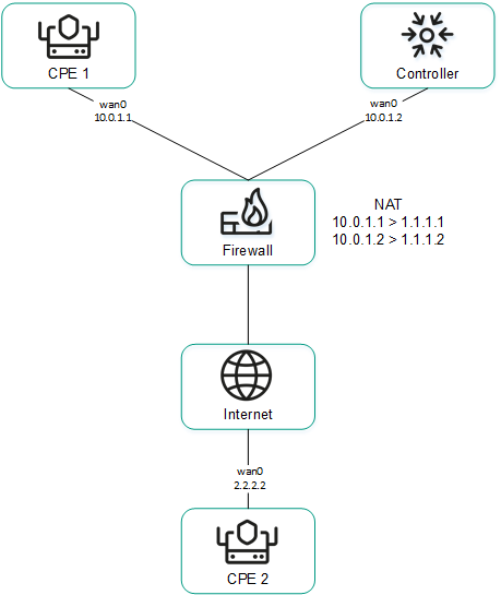
CPE 1 and the controller are behind NAT and are connected to CPE 2
Sending IP addresses of SD-WAN interfaces of the WAN type located in an isolated network to the controller
SD-WAN interfaces of the WAN type may be on an isolated network without the possibility of establishing a management session with the controller, but they can be used to establish links. In this case, the controller cannot obtain information about the IP addresses of isolated SD-WAN interfaces of the WAN type and use it to establish links between CPE devices.
In the figure below, CPE 1 and CPE 2 have two SD-WAN interface of the WAN type each, but they can establish a management session with the controller only through wan0 because wan1 is on an isolated network (MPLS) that does not have access to the controller. However, both wan1 interfaces can be used to establish links.
If the link used to interact with the controller fails for one of the CPE devices, all other links also cannot be used, even if they remain operational, because the Controller eliminates the device from the topology.
The IP addresses of isolated SD-WAN interfaces of the WAN type are sent to the controller through the orchestrator.
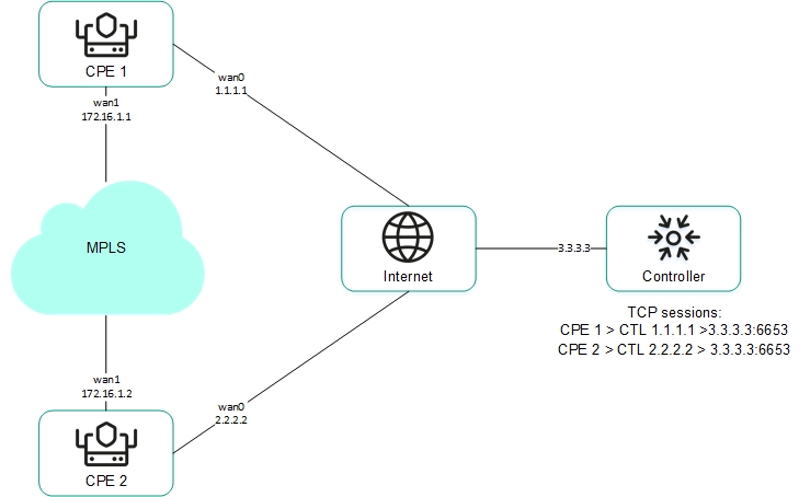
CPE 1 and CPE 2 are connected with each other through MPLS and with the controller through the Internet.
Page top
Package fragmentation
Kaspersky SD-WAN checks whether fragmentation of traffic packets is supported on CPE devices. A packet fragmentation test is started automatically. When each CPE device is enabled, it sends two ICMP requests to the IP addresses that you specified when creating or editing SD-WAN interfaces of the WAN type.
The ICMP requests have a packet size of 1600 bytes. If at least one of these requests receives a response, a conclusion is made that the CPE device supports packet fragmentation. You can view the fragmentation test result in the Fragmentation column of the CPE device table or the link table.
Page top
Traffic queues on SD-WAN interfaces
A maximum of 8 traffic queues can be used on SD-WAN interfaces. For each traffic queue, you must specify the minimum and maximum bandwidth as a percentage of the total bandwidth set for the SD-WAN interface. The sum total of all minimum bandwidth values specified for traffic queues may not exceed 100%.
The traffic queues are strict priority and unreserved bandwidth is first offered to traffic from the higher-priority queue. Each traffic queue is guaranteed certain minimum bandwidth in accordance with its specified minimum bandwidth value. An upper limit on the maximum bandwidth for higher-priority queues is necessary to allow traffic from lower-priority traffic queues to still be transmitted.
You can configure traffic queues when creating SD-WAN interfaces of the WAN type or editing SD-WAN interfaces of the WAN or LAN type.
Service providers can use different quality of service policies to mark traffic queues in their networks and meet SLA requirements for the passage of client traffic. Therefore, when simultaneously connecting to the networks of different service providers, CPE devices can relabel traffic of different queues for each SD-WAN interface of the WAN type. To configure relabeling, you must change the type of service (ToS) when configuring queues on an SD-WAN interface.
You can only change the ToS values of external headers of traffic packets originating from SD-WAN interfaces of the WAN type. ToS values of internal traffic packet headers cannot be edited.
Page top
Creating an SD-WAN interface of the WAN type
You can create an SD-WAN interface of the WAN type in a CPE template or on a CPE device. An SD-WAN interface of the WAN type created in a CPE template is automatically created on all CPE devices that are using this CPE template.
To create an SD-WAN interface of the WAN type:
- Create an SD-WAN interface of the WAN type in one of the following ways:
- If you want to create an SD-WAN interface of the WAN type in a CPE template, go to the SD-WAN → CPE templates menu section, click the CPE template, and select the SD-WAN settings → Interfaces tab.
- If you want to create an SD-WAN interface of the WAN type on a CPE device, go to the SD-WAN → CPE menu section, click the CPE device, and select the SD-WAN settings → Interfaces tab.
A table of SD-WAN interfaces is displayed.
- Click + SD-WAN interface.
- This opens a window; in that window, in the OpenFlow interface field, enter the number of the OpenFlow port that you are creating on the virtual switch.
- In the Interface (alias) field, enter the name of the created network interface, which the SD-WAN interface of the WAN type is mapped to.
- In the Maximum rate field, enter the maximum speed of the SD-WAN interface of the WAN type in Mbps. Range of values: 1 to 100,000. Default value:
1000. - Configure the availability check of the WAN to which the SD-WAN interface of the WAN type is connected:
- Specify the host for checking WAN availability. To do so, under IP for tracking, enter the IP address of the host and click + Add.
The host is specified and displayed under IP for tracking. You can specify multiple hosts or delete a host. To delete a host, click the delete icon
next to it. - In the IP for fragmentation check field, enter the IPv4 address of the host up to which fragmentation support is checked. Default value: 1.1.1.1.
- In the Reliability field, enter the minimum number of successful checks that makes the WAN available. Default value:
1.Make sure that the number of hosts does not exceed the number of IP addresses specified under IP for tracking. Otherwise, the WAN will always be considered unavailable.
- In the Interval field, enter the WAN check interval in seconds. Range of values: 1 to 600. Default value:
2. - In the Count field, enter the number of requests to hosts within one WAN check. Range of values: 1 to 600. Default value:
2. - In the Timeout field, enter the time to wait for a response from hosts, in milliseconds. Range of values: 1 to 100,000. Default value:
2000. - In the Down field, enter the number of unsuccessful checks that makes the WAN unavailable. Range of values: 1 to 600. Default value:
3. - In the Up field, enter the number of successful checks that makes the WAN available. Range of values: 1 to 600. Default value:
2. - In the Speed monitoring drop-down list, select whether the speed of the SD-WAN interface of the WAN type is being measured:
- Yes
- No Default value.
- Specify the host for checking WAN availability. To do so, under IP for tracking, enter the IP address of the host and click + Add.
- If you want to configure traffic queues on the SD-WAN interface of the WAN type:
- Select the QoS tab.
A table of traffic queues is displayed.
- In the Remap ToS column, select the Type of Service value of external headers of traffic packets for each queue.
- In the Minimum rate (%) column, specify the minimum traffic bandwidth for the queue as a percentage of the maximum speed of the SD-WAN interface of the WAN type. The sum total in a column may not exceed 100.
- In the Maximum rate (%) column, specify the maximum traffic bandwidth for the queue as a percentage of the maximum speed of the SD-WAN interface of the WAN type. This setting is used to prevent traffic of high-priority queues from indefinitely preempting traffic of low-priority queues.
The maximum speed of the SD-WAN interface of the WAN type is specified at step 5 of these instructions.
- Select the QoS tab.
- If you want to configure the sending of information about the SD-WAN interface of the WAN type to the controller:
- Select the NAT and disjoint WAN underlay tab.
- In the State drop-down list, select one of the following values:
- Disabled if you do not want information about the SD-WAN interface of the WAN type to be sent to the controller.
- NAT/PAT if the SD-WAN interface of the WAN type is behind NAT or PAT and needs to be assigned a public IP address and UDP port number, which must be sent to the controller.
- Disjoint WAN underlay if the SD-WAN interface of the WAN type is connected to an isolated network and its IP address must be communicated to the controller.
- If in the State drop-down list, you selected NAT/PAT, follow these steps:
- In the Real IP field, enter the public IPv4 address of the SD-WAN interface of the WAN type.
- In the Real GENEVE UDP port field, enter the UDP port number of the SD-WAN interface of the WAN type. Range of values: 1 to 65,535.
- If in the State drop-down list you selected Disjoint WAN underlay, enter the IPv4 address of the SD-WAN interface of the WAN type in the IP address field.
- If SD-WAN interfaces of the WAN type of the CPE device are connected to different networks, for example, the internet and a private MPLS network, you can change the IP addresses and TCP port numbers of controller nodes on individual SD-WAN interfaces of the WAN type. You can change the IP addresses and TCP port numbers of the controller nodes while configuring the controller nodes of an SD-WAN instance. This automatically changes the IP addresses and TCP port numbers of controller nodes on all CPE devices that are added to the SD-WAN instance. The IP addresses and TCP port numbers specified on the SD-WAN interface of the WAN type take precedence over the IP addresses and TCP port numbers specified when configuring the controller nodes of the SD-WAN instance.
To change the IP addresses and TCP port numbers of controller nodes on the SD-WAN interface of the WAN type:
- Select the Controllers tab.
- Select the Rewrite controllers IP/port check box. This check box is cleared by default.
- In the Number of controllers drop-down list, select the number of controller nodes.
You need to specify the number of controller nodes that you deployed when you deployed the SD-WAN instance. Otherwise, an error occurs and the settings remain unchanged.
- In the IP address field, enter the IPv4 address of the controller node. The number of fields corresponds to the value that you selected in the Number of controllers drop-down list.
- In the Port field, enter the base port number of the controller node. Range of values: 1 to 65,535. Default value:
6653. The number of fields corresponds to the value that you selected in the Number of controllers drop-down list.Along with the base port of the controller node, ports with the next three consecutive numbers are automatically specified. For example, if you enter the
6653as the base port number, ports 6654, 6655, and 6656 are automatically specified.
For the changes to take effect, you need to restart the CPE device after changing the IP addresses and TCP port numbers of controller nodes on the SD-WAN interface of the WAN type.
- Click Create.
The SD-WAN interface of the WAN type is created and displayed in the table.
- In the upper part of the settings area, click Save to save the settings of the CPE template or CPE device.
Editing an SD-WAN interface
You can edit an SD-WAN interface in a CPE template or on a CPE device. You cannot edit the name of an SD-WAN interface. When editing an SD-WAN interface of the LAN type, you can only configure the maximum speed and traffic queues. An SD-WAN interface edited in the CPE template is automatically modified on all CPE devices that use this CPE template.
To edit an SD-WAN interface:
- Edit an SD-WAN interface in one of the following ways:
- If you want to edit an SD-WAN interface in a CPE template, go to the SD-WAN → CPE templates menu section, click the CPE template, and select the SD-WAN settings → Interfaces tab.
- If you want to edit an SD-WAN interface on a CPE device, go to the SD-WAN → CPE menu section, click the CPE device, and select the SD-WAN settings → Interfaces tab. If you want to edit an SD-WAN interface inherited from the CPE template, select the Override check box next to that interface.
A table of SD-WAN interfaces is displayed.
- Click Edit next to the SD-WAN interface that you want to edit.
- This opens a window; in that window, edit the SD-WAN interface settings, if necessary. For a description of the settings, see the instructions for creating an interface of the WAN type.
- Click Save.
The SD-WAN interface is edited and updated in the table.
- In the upper part of the settings area, click Save to save the settings of the CPE template or CPE device.
Disabling or enabling an SD-WAN interface
You can disable or enable an SD-WAN interface in a CPE template or on a CPE device. An SD-WAN interface enabled or disabled in a CPE template is automatically enabled or disabled on all CPE devices that use this CPE template.
To disable or enable an SD-WAN interface:
- Disable or enable an SD-WAN interface in one of the following ways:
- If you want to enable or disable an SD-WAN interface in a CPE template, go to the SD-WAN → CPE templates menu section, click the CPE template, and select the SD-WAN settings → Interfaces tab.
- If you want to enable or disable an SD-WAN interface on a CPE device, go to the SD-WAN → CPE menu section, click the CPE device, and select the SD-WAN settings → Interfaces tab. If you want to disable or enable an SD-WAN interface inherited from the CPE template, select the Override check box next to that SD-WAN interface.
A table of SD-WAN interfaces is displayed.
- Click Disable or Enable next to the SD-WAN interface that you want to disable or enable.
The SD-WAN interface is disabled or enabled and updated in the table.
- In the upper part of the settings area, click Save to save the settings of the CPE template or CPE device.
Deleting an SD-WAN interface of the WAN type
You can delete an SD-WAN interface of the WAN type in a CPE template or on a CPE device. An SD-WAN interface of the WAN type deleted in a CPE template is automatically deleted on all CPE devices that are using this CPE template. You cannot delete an SD-WAN interface inherited from the CPE template on a CPE device, or delete an SD-WAN interface of the LAN type.
Deleted SD-WAN interfaces of the WAN type cannot be restored.
To delete an SD-WAN interface of the WAN type:
- Delete an SD-WAN interface of the WAN type in one of the following ways:
- If you want to delete an SD-WAN interface of the WAN type in a CPE template, go to the SD-WAN → CPE templates menu section, click the CPE template, and select the SD-WAN settings → Interfaces tab.
- If you want to delete an SD-WAN interface of the WAN type on a CPE device, go to the SD-WAN → CPE menu section, click the CPE device, and select the SD-WAN settings → Interfaces tab.
A table of SD-WAN interfaces is displayed.
- Click Delete next to the SD-WAN interface of the WAN type that you want to delete.
- In the confirmation window, click Delete.
The SD-WAN interface of the WAN type is deleted and is no longer displayed in the table.
- In the upper part of the settings area, click Save to save the settings of the CPE template or CPE device.
Managing service interfaces
Service interfaces are mapped to OpenFlow ports and are used to connect a CPE device to transport services. A service interface cannot be mapped to an OpenFlow port that is already mapped to an SD-WAN interface of the WAN type.
If you want to filter traffic packets on a service interface, you can create an Access Control List (ACL) interface that is mapped to this service interface. The ACL interface applies the specified traffic filter to the service interface. A single service interface can be mapped to at most four ACL interfaces.
To display the table of service interfaces, go to the Infrastructure menu section, click Management → Configuration menu next to the controller, and go to the Service interfaces section. Information about service interfaces is displayed in the following columns of the table:
- Port is the number of the OpenFlow port to which the service interface is mapped to.
- Type is the traffic classification type on the service interface.
- Access
- VLAN
- Q-in-Q
- ACL
- Description is a brief description of the service interface.
- VLAN is the outer VLAN tag of the service interface. The value in this column is only displayed for service interfaces with traffic classification types VLAN and Q-in-Q.
- Inner VLAN is the inner VLAN tag of the service interface. The value in this column is only displayed for service interfaces with traffic classification type Q-in-Q.
- Filter is the traffic filter for the ACL interface. The value in this column is only displayed for service interfaces with traffic classification type ACL.
- Name is the name of the service interface.
The actions you can perform with the table are described in the Managing solution component tables instructions.
Creating a service interface
To create a service interface:
- In the menu, go to the Infrastructure section.
This opens the resource management page. By default, the Network resources tab is selected, which displays the table of controllers.
- Click Management → Configuration menu next to the controller.
This opens the controller configuration menu. By default, you are taken to the Controller nodes section, which displays a table of controller nodes.
- Go to the Service interfaces section.
A table of service interfaces and ACL interfaces is displayed.
- In the Switch and Port drop-down lists, select the CPE device and the OpenFlow port to which the service interface is mapped.
- Click Create service interface.
- This opens a window; in that window, in the Type drop-down list, select the type of traffic classification on the service interface:
- Access Default value.
- VLAN If you select this option, in the VLAN ID field, enter the outer VLAN tag of the service interface. Range of values: 1 to 4094.
- Q-in-Q If you select this option, do the following:
- In the VLAN ID field, enter the outer VLAN tag of the service interface. Range of values: 1 to 4094.
- In the Inner VLAN ID field, enter the inner VLAN tag of the service interface. Range of values: 1 to 4094.
- ACL is used when creating an ACL interface.
- If necessary, enter a brief description of the service interface in the Description field.
- Click Create.
The service interface is created and displayed in the table.
Page top
Creating an ACL interface
To create an ACL interface:
- In the menu, go to the Infrastructure section.
This opens the resource management page. By default, the Network resources tab is selected, which displays the table of controllers.
- Click Management → Configuration menu next to the controller.
This opens the controller configuration menu. By default, you are taken to the Controller nodes section, which displays a table of controller nodes.
- Go to the Service interfaces section.
A table of service interfaces and ACL interfaces is displayed.
- In the Switch and Port drop-down lists, select the CPE device and the OpenFlow port to which the created service interface is mapped.
- Click + Create service interface.
- This opens a window; in that window, in the Type drop-down list, select ACL.
- In the Service interface drop-down list, select the service interface to which the ACL interface is mapped.
- In the Traffic fliter drop-down list, select the created traffic filter for the ACL interface. You can use the same traffic filter for multiple ACL interfaces.
- In the Sequence drop-down list, select the sequential number of the ACL interface. Traffic is directed first to the ACL interface with the lowest number. If the filter used on an ACL interface does not take in the traffic, the traffic is sent to the second ACL interface, and so on.
Range of values: 1 to 4. Two ACL interfaces with the same serial number cannot be mapped to the same service interface.
- If necessary, enter a brief description of the ACL interface in the Description field.
- Click Create.
The ACL interface is created and displayed in the table.
Viewing the usage of a service interface and an ACL interface
You can view which transport services are using a service interface or an ACL interface. A service interface or ACL interface that is in use cannot be deleted.
To view the usage of a service interface or ACL interface:
- In the menu, go to the Infrastructure section.
This opens the resource management page. By default, the Network resources tab is selected, which displays the table of controllers.
- Click Management → Configuration menu next to the controller.
- Go to the Service interfaces section.
A table of service interfaces and ACL interfaces is displayed.
- Click Management → Show usage next to the service interface or ACL interface for which you want to view usage information.
This opens a window with a table of transport services that are using the service interface or ACL interface.
tPage top
Deleting a service interface and an ACL interface
You cannot delete a service interface or an ACL interface if it is being used by at least one transport service. You must view the usage of a service interface or ACL interface and make sure that it is not being used.
Deleted service interfaces and ACL interfaces cannot be restored.
To delete a service interface or an ACL interface:
- In the menu, go to the Infrastructure section.
This opens the resource management page. By default, the Network resources tab is selected, which displays the table of controllers.
- Click Management → Configuration menu next to the controller.
- Go to the Service interfaces section.
A table of service interfaces and ACL interfaces is displayed.
- Click Management → Delete next to the service interface or ACL interface that you want to delete.
- In the confirmation window, click Delete.
The service interface or ACL interface is deleted and is no longer displayed in the table.
Page top
Managing OpenFlow port groups
OpenFlow ports are interfaces of the overlay SDN that are automatically created at the same time as the SD-WAN interfaces. The controller uses OpenFlow ports to control network traffic. You can create service interfaces and UNIs that are mapped to OpenFlow ports.
OpenFlow ports can be combined into OpenFlow port groups and used when creating P2M and M2M transport services. When you add an OpenFlow port group to a transport service, this automatically creates service interfaces mapped to the OpenFlow ports, and then these service interfaces are added to the transport service. Using groups of OpenFlow ports eliminates the need to manually create service interfaces and add them to transport services.
To display the table of OpenFlow port groups, go to the Infrastructure menu section, click Management → Configuration menu next to the controller, and go to the OpenFlow groups section. Information about groups of OpenFlow ports is displayed in the following columns of the table:
- Name is the name of the OpenFlow port group.
- Ports are OpenFlow ports that have been added to the OpenFlow ports group.
The actions you can perform with the table are described in the Managing solution component tables instructions.
Creating an OpenFlow port group
To create a group of OpenFlow ports:
- In the menu, go to the Infrastructure section.
This opens the resource management page. By default, the Network resources tab is selected, which displays the table of controllers.
- Click Management → Configuration menu next to the controller.
- Go to the OpenFlow groups section.
A table of groups of OpenFlow ports is displayed.
- In the upper part of the page, click + OpenFlow group.
- This opens a window; in that window, in the Name field, enter the name of the OpenFlow port group.
- In the Switch and Port drop-down lists, select the CPE device and OpenFlow port that you want to add to the OpenFlow port group.
- Click Create.
The group of OpenFlow interfaces is created and displayed in the table.
Page top
Editing an OpenFlow port group
To edit a group of OpenFlow ports:
- In the menu, go to the Infrastructure section.
This opens the resource management page. By default, the Network resources tab is selected, which displays the table of controllers.
- Click Management → Configuration menu next to the controller.
- Go to the OpenFlow groups section.
A table of groups of OpenFlow ports is displayed.
- Click Management → Edit next to the group of OpenFlow ports that you want to edit.
- This opens a window; in that window, if necessary, edit the name of the OpenFlow port group and add or delete OpenFlow ports.
- Click Save.
The OpenFlow port group is modified and updated in the table.
Page top
Deleting an OpenFlow port group
Deleted groups of OpenFlow ports cannot be restored.
To delete a group of OpenFlow ports:
- In the menu, go to the Infrastructure section.
This opens the resource management page. By default, the Network resources tab is selected, which displays the table of controllers.
- Click Management → Configuration menu next to the controller.
- Go to the OpenFlow groups section.
A table of groups of OpenFlow ports is displayed.
- Click Management → Delete next to the group of OpenFlow ports that you want to delete.
- In the confirmation window, click Delete.
The group of OpenFlow ports is deleted and is no longer displayed in the table.
Page top
Configuring a UNI for connecting CPE devices to network services
UNIs are mapped to OpenFlow ports and are used to connect a CPE device to network services. A UNI cannot be mapped to an OpenFlow port that is already mapped to an SD-WAN interface of the WAN type.
To avoid creating an UNI on each individual CPE device, you can create a UNI in a UNI template and then apply the UNI template to CPE devices when adding or manually registering them. If you edit a UNI in a UNI template, the UNI is automatically modified on all CPE devices that are using this UNI template.
When creating a UNI, a service interface is automatically created for it.
Managing UNI templates
The table of UNI templates is displayed in the SD-WAN → UNI templates section. Information about UNI templates is displayed in the following columns of the table:
- ID is the ID of the UNI template.
- Name is the name of the UNI template.
- Used indicates whether the UNI template is being used by CPE devices:
- Yes
- No
- Updated is the date and time when the UNI template settings were last modified.
- User is the name of the user which created the UNI template.
- Owner is the tenant to which the UNI template belongs.
The actions that you can perform with the table are described in the Managing solution component tables instructions.
UNI template settings are displayed on the following tabs:
- Information is the basic information about the UNI template. You can edit the name of the UNI template in the Name field.
- UNIs are UNIs that were created in the UNI template.
Creating a UNI template
To create a UNI template:
- In the menu, go to the SD-WAN → UNI templates subsection.
A table of UNI templates is displayed.
- In the upper part of the page, click + UNI template.
- This opens a window; in that window, enter the name of the UNI template.
- Click Create.
The UNI template is created and displayed in the table.
You need to configure the created UNI template. For a description of UNI template tabs, see the Managing UNI templates section.
Page top
Deleting a UNI template
Deleted UNI templates cannot be restored.
To delete a UNI template:
- In the menu, go to the SD-WAN → UNI templates subsection.
A table of UNI templates is displayed.
- Click the UNI template that you want to delete.
The settings area is displayed in the lower part of the page. You can expand the settings area to fill the entire page by clicking the expand icon
. By default, the Information tab is selected, which displays the UNI template name and the tenant to which the UNI template is assigned. - In the upper part of the settings area, under Actions, click Delete.
- In the confirmation window, click Delete.
The UNI template is deleted and is no longer displayed in the table.
Page top
Managing UNIs
Managing UNIs in a UNI template
To display the table of UNIs in a UNI template, go to the SD-WAN → UNI templates menu section, click the UNI template, and select the UNIs tab. Information about UNIs is displayed in the following columns of the table:
- Name is the name of the UNI.
- OpenFlow interface is the number of the OpenFlow port mapped to the UNI.
- Encapsulation is the traffic classification type on the UNI:
- Access
- VLAN
- Q-in-Q
- Actions contains the actions can be performed with the UNI.
Managing UNIs on a CPE device
To display the list of UNIs on a CPE device, go to the SD-WAN → CPE menu section, click the CPE device, and select the UNIs tab.
Creating a UNI
You can create a UNI in a UNI template or on a CPE device. A UNI created in the UNI template is automatically created on all CPE devices that use this UNI template.
To create a UNI:
- Create a UNI in one of the following ways:
- If you want to create a UNI in a UNI template, go to the SD-WAN → UNI templates menu section, click the UNI template, and select the UNIs tab.
- If you want to create an UNI on a CPE device, go to the SD-WAN → CPE menu section, click the CPE device, and select the UNIs tab.
A table or list of UNIs is displayed.
- Click + UNI.
- This opens a window; in that window, in the Name field, enter the name of the UNI.
- Specify the OpenFlow port to which the UNI is mapped in one of the following ways:
- If you are creating a UNI in a UNI template, enter the OpenFlow port number in the OpenFlow interface field.
- If you are creating a UNI on a CPE device, select the OpenFlow port in the Port drop-down list.
- In the Encapsulation drop-down list, select the traffic classification type on the UNI:
- Access Default value.
- VLAN If you select this option, in the VLAN ID field, enter the outer VLAN tag of the UNI. Range of values: 1 to 4094.
- Q-in-Q If you select this option, do the following:
- In the VLAN ID field, enter the outer VLAN tag of the UNI. Range of values: 1 to 4094.
- In the Inner VLAN ID field, enter the inner VLAN tag of the UNI. Range of values: 1 to 4094.
- If you are creating a UNI on a CPE device, in the QoS drop-down list, select a created quality of service rule for the UNI.
- Click Create.
The UNI is created and displayed in the table or list.
- In the upper part of the settings area, click Save to save the settings of the UNI template or CPE device.
Viewing UNI usage
You can see which network services are using the UNI on a CPE device. If a UNI template is in use, it cannot be deleted.
To view UNI usage:
- In the menu, go to the SD-WAN → CPE section.
A table of CPE devices is displayed.
- Click the CPE device on which you want to view UNI usage.
The settings area is displayed in the lower part of the page. You can expand the settings area to fill the entire page by clicking the expand icon
. By default, the Configuration tab is selected, which displays general information about the CPE device. This tab also displays the table of Out-of-band management tasks being performed by the orchestrator. - Select the UNIs tab.
A list of UNIs is displayed.
- Click Management → Show usage next to the UNI whose usage you want to view.
This opens a window with a table of network services that are using the UNI.
Page top
Editing a UNI
You can edit a UNI in a UNI template. A UNI edited in the UNI template is automatically modified on all CPE devices that use this UNI template.
To edit a UNI:
- In the menu, go to the SD-WAN → UNI templates subsection.
A table of UNI templates is displayed.
- Click the UNI template in which you want to edit a UNI.
The settings area is displayed in the lower part of the page. You can expand the settings area to fill the entire page by clicking the expand icon
. By default, the Information tab is selected, which displays the UNI template name and the tenant to which the UNI template is assigned. - Select the UNI tab.
A table of UNIs is displayed.
- Click Edit next to the UNI that you want to edit.
- This opens a window; in that window, if necessary, edit the UNI settings. For a description of the settings, see the instructions for creating a UNI.
- Click Save.
The UNI is modified and updated in the table.
- In the upper part of the settings area, click Save to save UNI template settings.
Deleting a UNI
You can delete a UNI in a UNI template or on a CPE device. A UNI deleted in the UNI template is automatically deleted on all CPE devices that use this UNI template.
Deleted UNIs cannot be restored.
Deleting a UNI in a UNI template
To delete a UNI in a UNI template:
- In the menu, go to the SD-WAN → UNI templates subsection.
A table of UNI templates is displayed.
- Click the UNI template in which you want to delete a UNI.
The settings area is displayed in the lower part of the page. You can expand the settings area to fill the entire page by clicking the expand icon
. By default, the Information tab is selected, which displays the UNI template name and the tenant to which the UNI template is assigned. - Select the UNIs tab.
A table of UNIs is displayed.
- Click Delete next to the UNI that you want to delete.
The UNI is deleted and is no longer displayed in the table.
- In the upper part of the settings area, click Save to save UNI template settings.
Deleting an UNI on a CPE device
You cannot delete a UNI if it is being used by at least one network service. You need to look up the usage of the UNI and make sure that it is not in use.
To delete a UNI on a CPE device:
- In the menu, go to the SD-WAN → CPE section.
A table of CPE devices is displayed.
- Click the CPE device on which you want to delete a UNI.
The settings area is displayed in the lower part of the page. You can expand the settings area to fill the entire page by clicking the expand icon
. By default, the Configuration tab is selected, which displays general information about the CPE device. This tab also displays the table of Out-of-band management tasks being performed by the orchestrator. - Select the UNIs tab.
A list of UNIs is displayed.
- Click Management → Delete next to the UNI that you want to delete.
- In the confirmation window, click Delete.
The UNI is deleted and is no longer displayed in the table.
- In the upper part of the settings area, click Save to save CPE device settings.
Adding a static route
In addition to dynamic route exchange between CPE devices and external network devices via BGP and OSPF protocols, Kaspersky SD-WAN supports static IPv4 routes. You can add a static route in a CPE template or on a CPE device. A static route added to the CPE template is automatically added to all CPE devices that use this CPE template.
To add a static route:
- Add a static route in one of the following ways:
- If you want to add a static route in a CPE template, go to the SD-WAN → CPE templates menu section, click the CPE template, and select the Static routes tab.
- If you want to add a static route on a CPE device, go to the SD-WAN → CPE menu section, click the CPE device, and select the Static routes tab and select the Override check box.
A table of static routes is displayed.
- Click the add static route icon .
- In the Interface drop-down list, select the created source network interface of the static route.
- In the Target field, enter the destination IPv4 address of the static route.
- If necessary, in the IPv4 netmask field, enter the IPv4 address of the destination subnet of the static route.
- In the Gateway field, enter the IP address of the gateway of the static route.
- In the Metric field, enter a metric for the static route. Default value:
0. - In the MTU field, enter the MTU value for the static route.
- In the Type drop-down list, select the type of the static route:
- unicast. Default value.
- local
- broadcast
- multicast
- unreachable
- prohibit
- blackhole
- anycast
- If you want to add a static route in a virtual routing and forwarding table, in the VRF drop-down list, select a created virtual routing and forwarding table. You must add the static route to the virtual routing table that contains the network interface of the source of the static route.
The static route is added and displayed in the table. You can add multiple static routes or delete a static route. To remove a static route, click the delete icon
 next to it.
 - In the upper part of the settings area, click Save to save the settings of the CPE template or CPE device.
Filtering routes and traffic packets
You can use the following mechanisms for route filtering when working with the BGP and OSPF protocols, and for filtering traffic packets when working with the PIM protocol:
- Access control lists (ACL) allow or deny the specified IPv4 prefixes.
- Prefix lists are an extended version of access control lists. These additionally allow or block IPv4 prefixes in the specified prefix length range. You can use prefix lists in route maps.
- Route maps are an extended version of prefix lists. Route maps additionally modify attribute values.
You can create rules in access control lists, prefix lists, and route maps. Each rule is numbered. The rule with the lowest sequence number is the first to be applied to an IPv4 prefix. If none of the rules can be applied, the IPv4 prefix is denied.
Managing access control lists (ACLs)
The table of access control lists is displayed in the CPE template and on the CPE device:
- To display the table of access control lists in a CPE template, go to the SD-WAN → CPE templates menu section, click the CPE template, and select the Routing filters → Access control lists tab.
- To display the table of access control lists on a CPE device, go to the SD-WAN → CPE menu section, click the CPE device, and select the Routing filters → Access control lists tab.
Information about access control lists is displayed in the following columns of the table:
- Name is the name of the access control list.
- Inherited indicates whether the access control list is inherited from the CPE template:
- Yes
- No
This column is displayed only on the CPE device.
- Sequence is the sequence number of the rule in the access control list. The rule with the lowest sequence number is the first to be applied to the IPv4 prefix by the access control list.
- Network is the IPv4 prefix to which the access control list applies the rule.
- Action is the action that the rule performs on the IPv4 prefix:
- Permit allows the IPv4 prefix.
- Deny — deny the IPv4 prefix.
- Management contains the actions that can be performed on the access control list.
Creating an access-control list
You can create an access control list in a CPE template or on a CPE device. An access control list created in the CPE template is automatically created on all CPE devices that use this CPE template.
To create an access control list:
- Create an access control list in one of the following ways:
- If you want to create an access control list in a CPE template, go to the SD-WAN → CPE templates menu section, click the CPE template, and select the Routing filters → Access control lists tab.
- If you want to create an access control list on a CPE device, go to the SD-WAN → CPE menu section, click the CPE device, and select the Routing filters → Access control lists tab and select the Override check box.
A table of access control lists is displayed.
- Click + Access control list.
- This opens a window; in that window, in the Name field, enter the name of the access control list. Maximum length: 50 characters. Do not use spaces in this field.
- Create a rule in the access control list:
- Click + Rule.
- In the Sequence field, enter the sequential number of the rule. The rule with the lowest sequence number is the first to be applied to the IPv4 prefix by the access control list. Range of values: 1 to 4,294,967,295.
- In the Network drop-down list, select the type of the rule:
- Any network for a rule that allows or denies all IPv4 prefixes.
- IP/mask for a rule that allows or denies the specified IPv4 prefix. Default value. If you select this value, enter the IPv4 prefix in the field that is displayed.
- In the Action drop-down list, select the action that the rule performs with the IPv4 prefix:
The rule is created. You can create multiple rules or delete a rule.
To delete a rule, click the delete icon next to it. - Click Create.
The access control list is created and displayed in the table.
- In the upper part of the settings area, click Save to save the settings of the CPE template or CPE device.
Editing an access control list
You can edit an access control list in the CPE template or on a CPE device. An access control list edited in the CPE template is automatically modified on all CPE devices that use this CPE template.
To edit an access control list:
- Edit an access control list in one of the following ways:
- If you want to edit an access control list in a CPE template, go to the SD-WAN → CPE templates menu section, click the CPE template, and select the Routing filters → Access control lists tab.
- If you want to edit an access control list on a CPE device, go to the SD-WAN → CPE menu section, click the CPE device, and select the Routing filters → Access control lists tab and select the Override check box.
A table of access control lists is displayed.
- Click Edit next to the access control list that you want to edit.
- This opens a window; in that window, if necessary, edit the settings of the access control list. For a description of the settings, see the instructions for creating an access control list.
- Click Save.
The access control list is modified and updated in the table.
- In the upper part of the settings area, click Save to save the settings of the CPE template or CPE device.
Deleting an access control list
You can delete an access control list in the CPE template or on a CPE device. An access control list deleted in the CPE template is automatically deleted on all CPE devices that use this CPE template.
Deleted access control lists cannot be restored.
To delete an access control list:
- Delete an access control list in one of the following ways:
- If you want to delete an access control list in a CPE template, go to the SD-WAN → CPE templates menu section, click the CPE template, and select the Routing filters → Access control lists tab.
- If you want to delete an access control list on a CPE device, go to the SD-WAN → CPE menu section, click the CPE device, and select the Routing filters → Access control lists tab and select the Override check box.
A table of access control lists is displayed.
- Click Delete next to the access control list that you want to delete.
- In the confirmation window, click Delete.
The access control list is deleted and is no longer displayed in the table.
- In the upper part of the settings area, click Save to save the settings of the CPE template or CPE device.
Managing prefix lists
The table of prefix lists is displayed in the CPE template and on the CPE device:
- To display the table of prefix lists in a CPE template, go to the SD-WAN → CPE templates menu section, click the CPE template, and select the Routing filters → Prefix lists tab.
- To display the table of prefix lists on a CPE device, go to the SD-WAN → CPE menu section, click the CPE device, and select the Routing filters → Prefix lists tab.
Information about prefix lists is displayed in the following columns of the table:
- Name is the name of the prefix list.
- Inherited indicates whether the prefix list is inherited from the CPE template:
- Yes
- No
This column is displayed only on the CPE device.
- Sequence is the sequence number of the rule in the prefix list. The rule with the lowest sequence number is the first to be applied to the IPv4 prefix by the prefix list.
- Network is the IPv4 prefix to which the prefix list applies the rule.
- Action is the action that the rule performs on the IPv4 prefix:
- Permit allows the IPv4 prefix.
- Deny blocks the IPv4 prefix.
- Greater or equal is starting value of the prefix length range to which the prefix list applies the rule.
- Less or equal is the ending value of the prefix length range to which the prefix list applies the rule.
- Management contains the actions that can be performed on the prefix list.
Creating a prefix list
You can create a prefix list in the CPE template or on a CPE device. A prefix list created in the CPE template is automatically created on all CPE devices that use this CPE template.
To create a prefix list:
- Create a prefix list in one of the following ways:
- If you want to create a prefix list in a CPE template, go to the SD-WAN → CPE templates menu section, click the CPE template, and select the Routing filters → Prefix lists tab.
- If you want to create a prefix list on a CPE device, go to the SD-WAN menu section, click the CPE device, select the Routing filters → Prefix lists tab, and select the Override check box.
A table of prefix lists is displayed.
- Click + Prefix list.
- This opens a window; in that window, in the Name field, enter the name of the prefix list. Maximum length: 50 characters. Do not use spaces in this field.
- Create a rule in the prefix list:
- Click + Rule.
- In the Sequence field, enter the sequential number of the rule. The rule with the lowest sequence number is the first to be applied to the IPv4 prefix by the prefix list. Range of values: 1 to 4,294,967,295.
- In the Network drop-down list, select the type of the rule:
- Any network for a rule that allows or denies all IPv4 prefixes.
- IP/mask for a rule that allows or denies the specified IPv4 prefix. Default value. If you select this value, enter the IPv4 prefix in the field that is displayed.
- In the Action drop-down list, select the action that the rule performs with the IPv4 prefix:
- In the Greater or equal field, enter the starting value of the prefix length range to which the prefix list applies the rule. Range of values: 0 to 32.
- In the Less or equal field, enter the ending value of the prefix length range to which the prefix list applies the rule. Range of values: 0 to 32.
The rule is created. You can create multiple rules or delete a rule.
To delete a rule, click the delete icon next to it. - Click Create.
The prefix list is created and displayed in the table.
- In the upper part of the settings area, click Save to save the settings of the CPE template or CPE device.
Editing a prefix list
You can edit a prefix list in a CPE template or on a CPE device. An prefix list edited in the CPE template is automatically modified on all CPE devices that use this CPE template.
To edit a prefix list:
- Edit a prefix list in one of the following ways:
- If you want to edit a prefix list in a CPE template, go to the SD-WAN → CPE templates menu section, click the CPE template, and select the Routing filters → Prefix lists tab.
- If you want to edit a prefix list on a CPE device, go to the SD-WAN menu section, click the CPE device, select the Routing filters → Prefix lists tab, and select the Override check box.
A table of prefix lists is displayed.
- Click Edit next to the prefix list that you want to edit.
- This opens a window; in that window, if necessary, edit the settings of the prefix list. For a description of the settings, see the instructions for creating a prefix list.
- Click Save.
The prefix list is modified and updated in the table.
- In the upper part of the settings area, click Save to save the settings of the CPE template or CPE device.
Deleting a prefix list
You can delete a prefix list in a CPE template or on a CPE device. A prefix list deleted in the CPE template is automatically deleted on all CPE devices that use this CPE template.
Deleted prefix lists cannot be restored.
To delete a prefix list:
- Delete a prefix list in one of the following ways:
- If you want to delete a prefix list in a CPE template, go to the SD-WAN → CPE templates menu section, click the CPE template, and select the Routing filters → Prefix lists tab.
- If you want to delete a prefix list on a CPE device, go to the SD-WAN → CPE menu section, click the CPE device, select the Routing filters → Prefix lists tab, and select the Override check box.
A table of prefix lists is displayed.
- Click Delete next to the prefix list that you want to delete.
- In the confirmation window, click Delete.
The prefix list is deleted and is no longer displayed in the table.
- In the upper part of the settings area, click Save to save the settings of the CPE template or CPE device.
Managing route maps
The table of route maps is displayed in the CPE template and on the CPE device:
- To display the table of route maps lists in a CPE template, go to the SD-WAN → CPE templates menu section, click the CPE template, and select the Routing filters → Route maps tab.
- To display the table of route maps on a CPE device, go to the SD-WAN → CPE menu section, click the CPE device, and select the Routing filters → Route maps tab.
Information about route maps is displayed in the following columns of the table:
- Name is the name of the route map.
- Inherited indicates whether the route map inherited from CPE template:
- Yes
- No
This column is displayed only on the CPE device.
- Sequence is the sequence number of the rule in the route map. The rule with the lowest sequence number is the first to be applied to the IPv4 prefix by the route map.
- Action is the action that the rule performs on the IPv4 prefix:
- Permit allows the IPv4 prefix.
- Deny blocks the IPv4 prefix.
- Match type is the criterion that makes the route map apply the rule to the IPv4 prefix:
- None applies the rule to all IPv4 prefixes.
- Prefix-List applies the rule to IPv4 prefixes allowed by the specified prefix list.
- Value is a prefix list that must allow the IPv4 prefix to let the route map apply the rule to this IPv4 prefix. This column displays a value only if the Match type column displays Prefix-List.
- Change attribute is the attribute whose value changes the rule.
- New value is the value that the rule sets for the attribute.
- Management contains the actions that can be performed with the route map.
Creating a route map
You can create a route map in a CPE template or on a CPE device. A route map created in the CPE template is automatically created on all CPE devices that use this CPE template.
To create a route map:
- Create a route map in one of the following ways:
- If you want to create a route map in a CPE template, go to the SD-WAN → CPE templates menu section, click the CPE template, and select the Routing filters → Route maps tab.
- If you want to create a route map on a CPE device, go to the SD-WAN → CPE menu section, click the CPE device, select the Routing filters → Route maps tab, and select the Override check box.
A table of route maps is displayed.
- Click + Route map.
- This opens a window; in that window, in the Name field, enter the name of the route map. Maximum length: 50 characters. Do not use spaces in this field.
- Create a rule in the route map:
- Click + Rule.
- In the Sequence field, enter the sequential number of the rule. The rule with the lowest sequence number is the first to be applied to the IPv4 prefix by the route map. Range of values: 1 to 4,294,967,295.
- In the Action drop-down list, select the action that the rule performs with the IPv4 prefix:
- In the Match type drop-down list, select the criterion that makes the route map apply the rule to the IPv4 prefix:
- If in the Match type drop-down list, you selected Prefix-List, in the Change attribute drop-down list, select the attribute that the rule modifies:
The rule is created. You can create multiple rules or delete a rule.
To delete a rule, click the delete icon next to it. - Click Create.
The route map is created and displayed in the table.
- In the upper part of the settings area, click Save to save the settings of the CPE template or CPE device.
Editing a route map
You can edit a route map in a CPE template or on a CPE device. A route map edited in the CPE template is automatically edited on all CPE devices that use this CPE template.
If you want the changes you make to a route map to be immediately applied to the BGP peers or BGP peer groups that use that route map, select the BFD or Soft-reconfiguration inbound check box when creating or editing the BGP peer or BGP peer group.
To edit a route map:
- Edit a route map in one of the following ways:
- If you want to edit a route map in a CPE template, go to the SD-WAN → CPE templates menu section, click the CPE template, and in the displayed settings area, select the Routing filters → Route maps tab.
- If you want to edit a route map on a CPE device, go to the SD-WAN → CPE menu section, click the CPE device, and in the displayed settings area, select the Routing filters → Route maps tab and select the Override check box.
A table of route maps is displayed.
- Click Edit next to the route map that you want to edit.
- This opens a window; in that window, if necessary, edit the route map settings. For a description of the settings, see the instructions for creating a route map.
- Click Save.
The route map is modified and updated in the table.
- In the upper part of the settings area, click Save to save the settings of the CPE template or CPE device.
Deleting a route map
You can delete a route map in a CPE template or on a CPE device. A route map deleted in the CPE template is automatically deleted on all CPE devices that use this CPE template.
Deleted route maps cannot be restored.
To delete a route map:
- Delete a route map in one of the following ways:
- If you want to delete a route map in a CPE template, go to the SD-WAN → CPE templates menu section, click the CPE template, and select the Routing filters → Route maps tab.
- If you want to delete a route map on a CPE device, go to the SD-WAN → CPE menu section, click the CPE device, select the Routing filters → Route maps tab, and select the Override check box.
A table of route maps is displayed.
- Click Delete next to the route map that you want to delete.
- In the confirmation window, click Delete.
The route map is deleted and is no longer displayed in the table.
- In the upper part of the settings area, click Save to save the settings of the CPE template or CPE device.
Route exchange over BGP
Kaspersky SD-WAN supports the BGP (Border Gateway Protocol) dynamic routing protocol for exchanging routing information between CPE devices and external network devices. You can establish internal iBGP (internal BGP) sessions as well as external eBGP (external BGP) sessions.
Creation of individual BGP peers and BGP peer groups is also supported. Dynamic TCP sessions are established with BGP peer groups.
The figures below show examples of BGP being used in the solution:
- Connecting multiple client locations to the L3 SD-WAN network via BGP.
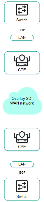
- Connecting CPE devices to the service provider's IP/MPLS network via BGP.
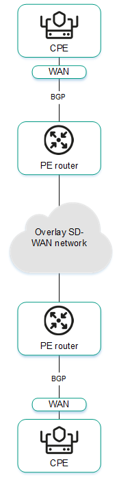
- Using BGP to configure the connectivity of CPE devices within the domain.
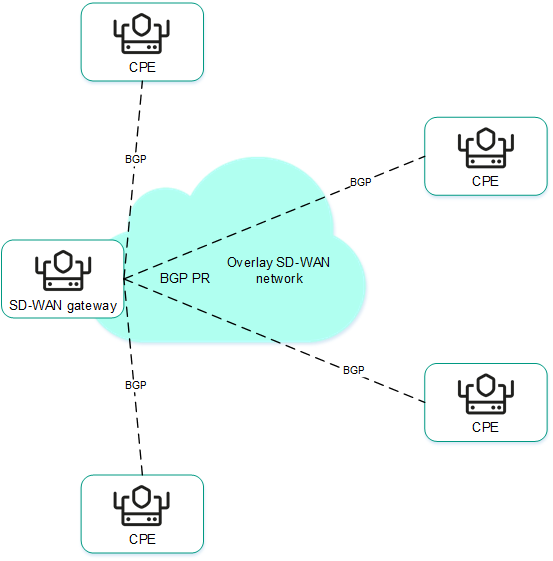
Basic BGP settings
You can specify basic BGP settings in a CPE template or on a CPE device. BGP settings specified in the CPE template are automatically propagated to all CPE devices that use this CPE template.
To modify the basic BGP settings:
- Specify basic BGP settings in one of the following ways:
- If you want to edit the basic BGP settings in a CPE template, go to the SD-WAN → CPE templates menu section, click the CPE template, and select the BGP settings → General settings tab.
- If you want to edit the basic BGP settings on a CPE device, go to the SD-WAN → CPE menu section, click the CPE device, select the BGP settings → General settings tab, and select the Override check box.
Basic BGP settings are displayed.
- In the BGP drop-down list, select Enabled. The default value is Disabled.
- If you want to add BGP routes to the specified virtual routing and forwarding table, in the VRF drop-down list, select a created virtual routing and forwarding table.
- In the AS field, enter the autonomous system number of the CPE device. Range of values: 1 to 4,294,967,295.
- In the Router ID field, enter the IPv4 address that you want to assign to the router ID of the CPE device. If you want to assign an IPv4 address from a specified range of IP addresses:
- Select the Get router ID from IP pool check box. This check box is cleared by default.
- In the IP Pool drop-down list, select a created range of IP addresses.
- If necessary, in the Maximum paths field, enter the maximum number of entries in the routing and forwarding table of the CPE device. Range of values: 1 to 8.
- If necessary, select the following check boxes:
- Select the Always compare MED check box. This check box allows the CPE device to compare the multi-exit discriminator (MED) of routes advertised from different autonomous systems.
You must make sure that this check box is selected on all CPE devices in your autonomous system. Otherwise, exchange of routing information may result in routing loops.
- Select the Graceful restart (helper mode) check box to enable Graceful restart on the CPE device.
These check boxes are cleared by default.
- Select the Always compare MED check box. This check box allows the CPE device to compare the multi-exit discriminator (MED) of routes advertised from different autonomous systems.
- If you do not want the CPE device to exchange IPv4 routes with BGP peers by default, clear the Use default IPv4 unicast routes check box. This check box is selected by default.
- If you want to configure BGP timers:
- Select the BGP timers check box. This check box is cleared by default.
- In the Keepalive field, enter the time interval in seconds that the CPE device uses to send control packets to BGP peers. Range of values: 0 to 65,535.
- In the Holdtime field, enter the time interval in seconds that the CPE device uses when receiving control packets from BGP peers. If no control packets are received from the BGP peer within the specified time, the CPE device considers the peer unavailable. Range of values: 0 to 65,535.
- If you want to configure route redistribution in BGP, under Route redistribution, do the following:
- Select the check boxes next to the route types:
- Kernel to redistribute Kernel routes generated by the operating system of the CPE device.
- Connected to redistribute routes directly connected to network interfaces of CPE device.
- Static to redistribute static routes.
- OSPF to redistribute OSPF routes.
These check boxes are cleared by default.
- In the Route map drop-down list, select a created route map for redistributed routes.
- In the Metric field, enter a metric of redistributed routes. Range of values: 0 to 16,777,214.
- Select the check boxes next to the route types:
- If you want the CPE device to advertise the specified subnet to BGP peers:
- Under Networks, click + Network.
- In the Network field, enter the IPv4 prefix of the subnet.
- In the Route map drop-down list, select a created route map for the subnet.
The subnet is specified and displayed under Networks. You can specify multiple subnets or delete a subnet. To delete a subnet, click the delete icon
next to it. - In the upper part of the settings area, click Save to save the settings of the CPE template or CPE device.
Managing BGP peers
The table of BGP peers is displayed in the CPE template and on the CPE device:
- To display the table of BGP peers in a CPE template, go to the SD-WAN → CPE templates menu section, click the CPE template, and select the BGP settings → Neighbors tab.
- To display the table of BGP peers on a CPE device, go to the SD-WAN → CPE menu section, click the CPE device, and select the BGP settings → Neighbors tab.
Information about BGP peers is displayed in the following columns of the table:
- Neighbor IP is the IPv4 address of the BGP peer.
- Name is the name of the BGP peer.
- Description is a brief description of the BGP peer.
- Inherited indicates whether the BGP peer is inherited from the CPE template:
- Yes
- No
This column is displayed only on the CPE device.
- Remote AS is the autonomous system number of the BGP peer.
- Shutdown indicates whether the BGP peer is disabled and no TCP session is established with it:
- Yes
- No
- Weight is the weight of routes advertised by the BGP peer.
- Management contains the actions that can be performed with the BGP peer.
Creating a BGP peer
You can create a BGP peer in a CPE template or on a CPE device. A BGP peer created in the CPE template is automatically created on all CPE devices that use this CPE template. The maximum number of dynamic BGP peers is 512.
To create a BGP peer:
- Create a BGP peer in one of the following ways:
- If you want to create a BGP peer in a CPE template, go to the SD-WAN → CPE templates menu section, click the CPE template, and select the BGP settings → Neighbors tab.
- If you want to create a BGP peer on a CPE device, go to the SD-WAN → CPE menu section, click the CPE device, select the BGP settings → Neighbors tab, and select the Override check box.
A table of BGP peers is displayed.
- Click + BGP neighbor.
- This opens a window; in that window, in the Name field, enter the name of the BGP peer. Maximum length: 50 characters.
- If you want to disable a BGP peer and prevent establishing a TCP session with it, select the Disable BGP peer check box. This check box is cleared by default.
- In the Neighbor IP field, enter the IPv4 address of the BGP peer.
- In the Remote AS field, enter the autonomous system number of the BGP peer. Range of values: 1 to 4,294,967,295.
- If necessary, enter a brief description of the BGP peer in the Description field.
- If you want the CPE device to use a password when establishing a TCP session with the BGP peer, in the Password field, enter the password. For a TCP session to be successfully established between two BGP peers, they must use the same password. To see the entered password, you can click the show icon .
- If necessary, in the Loopback interface field, enter the IPv4 address of the loopback interface that the CPE device sends to the BGP peer when establishing a TCP session.
- If the TCP session is not established directly between the CPE device and the BGP peer, in the eBGP hops field, enter the number of hops between the CPE device and the BGP peer. Range of values: 1 to 255.
- If you want to configure BGP timers:
- Select the Custom BGP timers check box. This check box is cleared by default.
- In the Keepalive field, enter the time interval in seconds that the CPE device uses to send control packets to the BGP peer. Range of values: 0 to 65,535.
- In the Holdtime field, enter the time interval in seconds that the CPE device uses when receiving control packets from the BGP peer. If no control packets are received from the BGP peer within the specified time, the CPE device considers the peer unavailable. Range of values: 0 to 65,535.
- If you want to use the BFD protocol to detect loss of connectivity, select the BFD check box. This check box is cleared by default. When the check box is selected, changes you make to the route map are immediately applied to a BGP peer if the BGP peer uses this route map. You can select a route map for the BGP peer at step 14 of these instructions.
- If you want to specify advanced settings for the BGP peer:
- Select the Advanced settings tab.
Advanced settings of the BGP peer are displayed.
- If necessary, select the following check boxes:
- Select the Soft-reconfiguration inbound check box to store routes advertised by the BGP peer locally on the CPE device. Using this feature reduces the amount of memory available on the CPE device. When the check box is selected, changes you make to the route map are immediately applied to a BGP peer if the BGP peer uses this route map. You can select a route map for the BGP peer at step 14 of these instructions.
- Select the Attribute unchanged AS path check box to prevent modifying the 'AS path' attribute of routes that the CPE device advertises to the BGP peer.
- Select the Allow AS in check box to let BGP peers advertise routes to the CPE device with the 'AS path' attribute, whose value is the autonomous system number of the CPE device.
- Select the Attribute unchanged next-hop check box to prevent modifying the 'next hop' attribute of routes that the CPE device advertises to the BGP peer.
- Select the Next-hop self check box to use the IPv4 address of the CPE device as the 'next-hop' attribute value when advertising routes to the BGP peer.
- Select the Attribute unchanged MED check box to prevent modifying the 'MED' attribute of routes that the CPE device advertises to the BGP peer.
- Select the Route reflector client check box to assign the Route Reflector role to the CPE device and the Route Reflector Client role to the BGP peer. You can only select this check box for a BGP peer that is in the same autonomous system as the CPE device.
These check boxes are cleared by default.
- In the Local AS field, enter the number of the local autonomous system that the CPE device must send to the BGP peer. Range of values: 1 to 4,294,967,295.
- In the Weight field, enter the weight of the routes advertised by the BGP peer. The greater the weight of a route, the higher its priority. Range of values: 0 to 65,535.
- In the Maximum prefix field, enter the maximum number of routes that the BGP peer can advertise to a CPE device. Range of values: 1 to 4,294,967,295.
- If you want a CPE device to advertise routes with the 'community' attribute to its BGP peer, select the Send community check box and select the type of the attribute in the drop-down list:
- All covers all available types of the 'community' attribute.
- Standard and extended community.
- Extended community.
- Large community.
- Standard community.
This check box is cleared by default.
- If you want the CPE device to advertise the default 0.0.0.0/0 route to the BGP peer, select the Default originate check box. This check box is cleared by default. You can select the Set route map check box and in the drop-down list that is displayed, select the created route map for the 0.0.0.0/0 default route.
- Select the Advanced settings tab.
- If you want to configure route filtering for the BGP peer:
- Select the Filtering tab.
The route filtering settings are displayed.
- Under Route map, select the created route maps:
- In the Inbound drop-down list, select a route map for the routes that the BGP peer advertises to the CPE device.
- In the Outbound drop-down list, select a route map for the routes that the CPE device advertises to the BGP peer.
- Under Prefix list, select the created prefix lists:
- In the Inbound drop-down list, select a prefix list for the routes that the BGP peer advertises to the CPE device.
- In the Outbound drop-down list, select a prefix list for the routes that the CPE device advertises to the BGP peer.
- Under Access control list, select the created access control lists:
- In the Inbound drop-down list, select an access control list for the routes that the BGP peer advertises to the CPE device.
- In the Outbound drop-down list, select an access control list for the routes that the CPE device advertises to the BGP peer.
- Select the Filtering tab.
- Click Create.
The BGP peer is created and displayed in the table.
- In the upper part of the settings area, click Save to save the settings of the CPE template or CPE device.
Editing a BGP peer
You can edit a BGP peer in a CPE template or on a CPE device. A BGP peer edited in the CPE template is automatically modified on all CPE devices that use this CPE template. You cannot edit a BGP peer that is inherited from a CPE template on a CPE device.
To edit a BGP peer:
- Edit a BGP peer in one of the following ways:
- If you want to edit a BGP peer in a CPE template, go to the SD-WAN → CPE templates menu section, click the CPE template, and select the BGP settings → Neighbors tab.
- If you want to edit a BGP peer on a CPE device, go to the SD-WAN → CPE menu section, click the CPE device, select the BGP settings → Neighbors tab, and select the Override check box.
A table of BGP peers is displayed.
- Click Edit next to the BGP peer that you want to edit.
- This opens a window; in that window, if necessary, edit the BGP peer settings. For a description of the settings, see the instructions for creating a BGP peer.
- Click Save.
The BGP peer is modified and updated in the table.
- In the upper part of the settings area, click Save to save the settings of the CPE template or CPE device.
Deleting a BGP peer
You can delete a BGP peer in a CPE template or on a CPE device. A BGP peer deleted in the CPE template is automatically deleted on all CPE devices that use this CPE template. You cannot delete a BGP peer that is inherited from a CPE template on a CPE device.
Deleted BGP peers cannot be restored.
To delete a BGP peer:
- Delete a BGP peer in one of the following ways:
- If you want to delete a BGP peer in a CPE template, go to the SD-WAN → CPE templates menu section, click the CPE template, and select the BGP settings → Neighbors tab.
- If you want to delete a BGP peer on a CPE device, go to the SD-WAN → CPE menu section, click the CPE device, select the BGP settings → Neighbors tab, and select the Override check box.
A table of BGP peers is displayed.
- Click Delete next to the BGP peer that you want to delete.
- In the confirmation window, click Delete.
The BGP peer is deleted and is no longer displayed in the table.
- In the upper part of the settings area, click Save to save the settings of the CPE template or CPE device.
Managing BGP peer groups
The table of BGP peer groups is displayed in the CPE template and on the CPE device:
- To display the table of BGP peer groups in a CPE template, go to the SD-WAN → CPE templates menu section, click the CPE template, and select the BGP settings → Peer groups tab.
- To display the table of BGP peer groups on a CPE device, go to the SD-WAN → CPE menu section, click the CPE device, select the BGP settings → Peer groups tab, and select the Override check box.
Information about BGP peer groups is displayed in the following columns of the table:
- Name is the name of the BGP peer group.
- BGP range is the IPv4 prefix of the BGP peer group.
- Description is a brief description of the BGP peer group.
- Inherited indicates whether the BGP peer group is inherited from the CPE template:
- Yes
- No
This column is displayed only on the CPE device.
- Remote AS is the autonomous system number of the BGP peer group.
- Shutdown indicates whether the BGP peer group is disabled and no TCP session is established with it.
- Yes
- No
- Weight is the weight of routes advertised by the BGP peer group.
- Management contains the actions that can be performed with the BGP peer group.
Creating a BGP peer group
You can create a BGP peer group in a CPE template or on a CPE device. A BGP peer group created in the CPE template is automatically created on all CPE devices that use this CPE template.
To create a BGP peer group:
- Create a BGP peer group in one of the following ways:
- If you want to create a BGP peer group in a CPE template, go to the SD-WAN → CPE templates menu section, click the CPE template, and select the BGP settings → Peer groups tab.
- If you want to create a BGP peer group on a CPE device, go to the SD-WAN → CPE menu section, click the CPE device, select the BGP settings → Peer groups tab, and select the Override check box.
A table of BGP peer groups is displayed.
- Click + Peer group.
- This opens a window; in that window, in the Name field, enter the name of the BGP peer group. Maximum length: 50 characters.
- If you want to disable a BGP peer group and prevent establishing a TCP session with it, select the Disable BGP peer group check box. This check box is cleared by default.
- In the BGP range field, enter the IPv4 prefix of the BGP peer group.
- In the Remote AS field, enter the autonomous system number of the BGP peer group. Range of values: 1 to 4,294,967,295.
- If necessary, enter a brief description of the BGP peer group in the Description field.
- If you want the CPE device to use a password when establishing a TCP session with the BGP peer group, in the Password field, enter the password. For a TCP session to be successfully established between two BGP peers, they must use the same password. To see the entered password, you can click the show icon .
- In the Loopback interface field, enter the IPv4 address of the loopback interface that the CPE device sends to the BGP peer group when establishing a TCP session.
- If the TCP session is not established directly between the CPE device and the BGP peer group, in the eBGP hops field, enter the number of hops between the CPE device and the BGP peer group. Range of values: 1 to 255.
- If you want to configure BGP timers:
- Select the Custom BGP timers check box. This check box is cleared by default.
- In the Keepalive field, enter the time interval in seconds that the CPE device uses to send control packets to the BGP peer group. Range of values: 0 to 65,535.
- In the Holdtime field, enter the time interval in seconds that the CPE device uses when receiving control packets from the BGP peer group. If no control packets are received from the BGP peer within the specified time, the CPE device considers the peer unavailable. Range of values: 0 to 65,535.
- If you want to use the BFD protocol to detect loss of connectivity, select the BFD check box. This check box is cleared by default. When the check box is selected, changes you make to the route map are immediately applied to a BGP peer group if the BGP peer group uses this route map. You can select a route map for the BGP peer group at step 14 of these instructions.
- If you want to specify advanced settings for the BGP peer group:
- Select the Advanced settings tab.
Advanced settings of the BGP peer group are displayed.
- If necessary, select the following check boxes:
- Select the Soft-reconfiguration inbound check box to store routes advertised by the BGP peer group locally on the CPE device. Using this feature reduces the amount of memory available on the CPE device. When the check box is selected, changes you make to the route map are immediately applied to a BGP peer group if the BGP peer group uses this route map. You can select a route map for the BGP peer group at step 14 of these instructions.
- Select the Attribute unchanged AS path check box to prevent modifying the 'AS path' attribute of routes that the CPE device advertises to the BGP peer group.
- Select the Allow AS in check box to let the BGP peer group advertise routes to the CPE device with the 'AS path' attribute, whose value is the autonomous system number of the CPE device.
- Select the Attribute unchanged next-hop check box to prevent modifying the 'next hop' attribute of routes that the CPE device advertises to the BGP peer group.
- Select the Next-hop self check box to use the IPv4 address of the CPE device as the 'next-hop' attribute value when advertising routes to the BGP peer group.
- Select the Attribute unchanged MED check box to prevent modifying the 'MED' attribute of routes that the CPE device advertises to the BGP peer group.
- Select the Route reflector client check box to assign the Route Reflector role to the CPE device and the Route Reflector Client role to the BGP peer group. You can only select this check box for a BGP peer group that is in the same autonomous system as the CPE device.
These check boxes are cleared by default.
- In the Local AS field, enter the number of the local autonomous system that the CPE device sends to the BGP peer group. Range of values: 1 to 4,294,967,295.
- In the Weight field, enter the weight of the routes advertised by the BGP peer group. The greater the weight of a route, the higher its priority. Range of values: 0 to 65,535.
- In the Maximum prefix field, enter the maximum number of routes that the BGP peer group can advertise to a CPE device. Range of values: 1 to 4,294,967,295.
- If you want a CPE device to advertise routes with the 'community' attribute to the BGP peer group, select the Send community check box and select the type of attribute to be sent in the drop-down list:
- All covers all available types of the 'community' attribute.
- Standard and extended community.
- Extended community.
- Large community.
- Standard community.
This check box is cleared by default.
- If you want the CPE device to advertise the default 0.0.0.0/0 route to the BGP peer group, select the Default originate check box. This check box is cleared by default. You can select the Set route map check box and in the drop-down list that is displayed, select the created route map for the 0.0.0.0/0 default route.
- Select the Advanced settings tab.
- If you want to configure route filtering for the BGP peer group:
- Select the Filtering tab.
The route filtering settings are displayed.
- Under Route map, select the created route maps:
- In the Inbound drop-down list, select a route map for the routes that the BGP peer group advertises to the CPE device.
- In the Outbound drop-down list, select a route map for the routes that the CPE device advertises to the BGP peer group.
- Under Prefix list, select the created prefix lists:
- In the Inbound drop-down list, select a list of prefixes that the BGP peer group advertises to the CPE device.
- In the Outbound drop-down list, select a prefix list for the routes that the CPE device advertises to the BGP peer group.
- Under Access control list, select the created access control lists:
- In the Inbound drop-down list, select an access control list for the routes that the BGP peer group advertises to the CPE device.
- In the Outbound drop-down list, select an access control list for the routes that the CPE device advertises to the BGP peer group.
- Select the Filtering tab.
- Click Create.
The BGP peer group is created and displayed in the table.
- In the upper part of the settings area, click Save to save the settings of the CPE template or CPE device.
Editing a BGP peer group
You can edit a BGP peer group in a CPE template or on a CPE device. A BGP peer group edited in the CPE template is automatically modified on all CPE devices that use this CPE template. You cannot edit a BGP peer group that is inherited from a CPE template on a CPE device.
To edit a BGP peer group:
- Edit a BGP peer group in one of the following ways:
- If you want to edit a BGP peer group in a CPE template, go to the SD-WAN → CPE templates menu section, click the CPE template, and select the BGP settings → Peer groups tab.
- If you want to edit a BGP peer group on a CPE device, go to the SD-WAN → CPE menu section, click the CPE device, select the BGP settings → Peer groups tab, and select the Override check box.
A table of BGP peer groups is displayed.
- Click Edit next to the BGP peer group that you want to edit.
- This opens a window; in that window, if necessary, edit the BGP peer group settings. For a description of the settings, see the instructions for creating a BGP peer group.
- Click Save.
The BGP peer group is modified and updated in the table.
- In the upper part of the settings area, click Save to save the settings of the CPE template or CPE device.
Deleting a BGP peer group
You can delete a BGP peer group in a CPE template or on a CPE device. A BGP peer group deleted in the CPE template is automatically deleted on all CPE devices that use this CPE template. You cannot delete a BGP peer group that is inherited from a CPE template on a CPE device.
Deleted BGP peer groups cannot be restored.
To delete a BGP peer group:
- Delete a BGP peer group in one of the following ways:
- If you want to delete a BGP peer group in a CPE template, go to the SD-WAN → CPE templates menu section, click the CPE template, and select the BGP settings → Peer groups tab.
- If you want to delete a BGP peer group on a CPE device, go to the SD-WAN → CPE menu section, click the CPE device, select the BGP settings → Peer groups tab, and select the Override check box.
A table of BGP peer groups is displayed.
- Click Delete next to the BGP peer group that you want to delete.
- In the confirmation window, click Delete.
The BGP peer group is deleted and is no longer displayed in the table.
- In the upper part of the settings area, click Save to save the settings of the CPE template or CPE device.
Route exchange over OSPF
Kaspersky SD-WAN supports the OSPF (Open Shortest Path First) dynamic routing protocol for exchanging routing information between CPE devices and external network devices. When configuring the OSPF protocol, you can use OSPF areas and OSPF interfaces.
Basic OSPF settings
You can specify basic OSPF settings in a CPE template or on a CPE device. Basic OSPF settings specified in the CPE template are automatically propagated to all CPE devices that use this CPE template.
To modify the basic OSPF settings:
- Specify basic OSPF settings in one of the following ways:
- If you want to edit the basic OSPF settings in a CPE template, go to the SD-WAN → CPE templates menu section, click the CPE template, and select the OSPF → General settings tab.
- If you want to edit the basic OSPF settings on a CPE device, go to the SD-WAN → CPE menu section, click the CPE device, select the OSPF → General settings tab, and select the Override check box.
The OSPF settings are displayed.
- In the OSPF drop-down list, select Enabled. The default value is Disabled.
- In the Router ID field, enter the IPv4 address that you want to assign to the router ID of the CPE device.
- In the Maximum paths field, enter the maximum number of entries in the routing and forwarding table of the CPE device. Range of values: 1 to 16.
- If you want to use the CPE device as an Area Border Router (ABR), in the ABR type drop-down list, select one of the following implementations:
- IBM (default implementation)
- CISCO
- SHORTCUT
- STANDARD
- In the Auto cost reference bandwidth field, enter the reference bandwidth for calculating the cost of links on the CPE device. Range of values: 1 to 4,294,967.
- If you want to switch all OSPF interfaces of the CPE device to passive mode, select the Passive interface default check box. In passive mode, OSPF interfaces do not exchange traffic packets. This check box is cleared by default.
- If you want to keep an OSPF log, select the Log adjacency changes check box. You can select the Log adjacency changes check box to keep a more verbose OSPF log. These check boxes are cleared by default.
- If you want to configure route redistribution in OSPF, under Route redistribution, do the following:
- Select the check boxes next to the route types:
- BGP to redistribute BGP routes.
- Connected to redistribute routes directly connected to network interfaces of CPE device.
- Kernel to redistribute Kernel routes generated by the operating system of the CPE device.
- Static to redistribute static routes.
These check boxes are cleared by default.
- In the Route map drop-down list, select a created route map for redistributed routes.
- In the Metric field, enter a metric of redistributed routes. Range of values: 0 to 16,777,214.
- In the Metric type drop-down list, select the type of the metric:
- Type 1 (or "internal metric")
- Type 2 (or "external metric")
- Select the Filtering check box and in the Access control list drop-down list, select a created access control list for reallocated routes. This check box is cleared by default.
- Select the check boxes next to the route types:
- In the Default metric field, enter the default metric of OSPF routes. Range of values: 0 to 16,777,214.
- If you want to configure the CPE device to advertise the default route 0.0.0.0/0 to OSPF neighbors:
- Select the Default originate check box. This check box is cleared by default.
- Select the Always check box to always advertise the default 0.0.0.0/0 route, even if it is not present in the route table of the CPE device. This check box is cleared by default.
- In the Metric type drop-down list, select the type of metric for the 0.0.0.0/0 default route:
- Type 1
- Type 2
- In the Metric field, enter a metric for the 0.0.0.0/0 default route. Range of values: 0 to 16,777,214.
- In the Route map drop-down list, select a created route map for the 0.0.0.0/0 default route.
- In the Distance field, enter the administrative distance for all OSPF routes. The lower the administrative distance specified for a protocol, the higher the priority its route have. For example, if you want OSPF routes to always be preferred over BGP routes, specify the administrative distance of 1 for OSPF and 2 for BGP. Range of values: 1 to 255.
- If you want to configure administrative distances for individual OSPF routes:
- Select the Distance OSPF check box. This check box is cleared by default.
- In the External field, enter the administrative distance for routes from external OSPF domains or routing protocols. Range of values: 1 to 255.
- In the Inter-area field, enter the administrative distance for routes from different OSPF areas of the same OSPF domain. Range of values: 1 to 255.
- In the Intra-area field, enter the administrative distance for routes from the same OSPF area. Range of values: 1 to 255.
- If you want to enable Graceful restart on the CPE device:
- Select the Graceful restart check box. This check box is cleared by default.
- In the Grace period (sec.) field, enter the length of time, in seconds, during which the CPE device announces its intention to restart to OSPF peers. Range of values: 1 to 1800.
- If you want to configure timers for the Shortest Path First (SPF) algorithm calculations:
- Select the Timers throttle SPF check box. This check box is cleared by default.
- In the Delay (sec.) field, enter the length in seconds of the delay before starting the calculations of the SPF algorithm. Range of values: 0 to 600,000.
- In the Initial hold-time (ms.) field, enter the minimum retention time in milliseconds between two calculations of the SPF algorithm. Range of values: 0 to 600,000.
- In the Maximum hold-time (ms.) field, enter the maximum retention time in milliseconds between two calculations of the SPF algorithm. Range of values: 0 to 600,000.
- If you want to configure Link State Advertisement (LSA) to OSPF neighbors for the CPE device:
- Select the Administrative check box to have the CPE device use the maximum metric in link state advertisements to OSPF neighbors.
- If you want to specify the time during which the CPE device must use the maximum metric in link state advertisement to OSPF neighbors when the OSPF protocol is started or restarted:
- Select the On startup check box. This check box is cleared by default.
- In the Timer (sec.) field, enter the time in seconds. Range of values: 5 to 86,400.
- If you want to specify the time during which the CPE device must use the maximum metric in link state advertisement to OSPF neighbors when the OSPF protocol is disabled:
- Select the On shutdown check box. This check box is cleared by default.
- In the Timer (sec.) field, enter the time in seconds. Range of values: 5 to 100.
- In the upper part of the settings area, click Save to save the settings of the CPE template or CPE device.
Managing OSPF areas
The table of OSPF areas is displayed in the CPE template and on the CPE device:
- To display the table of OSPF areas in a CPE template, go to the SD-WAN → CPE templates menu section, click the CPE template, and select the OSPF → OSPF areas tab.
- To display the table of OSPF areas on a CPE device, go to the SD-WAN → CPE menu section, click the CPE device, and select the OSPF → OSPF areas tab.
Information about OSPF areas is displayed in the following columns of the table:
- OSPF area is the ID of the OSPF area in IPv4 address format or an integer.
- Area type is the type of the OSPF stub area:
- Stub
- Stub NO-SUMMARY
- NSSA
- NSSA NO-SUMMARY
This value is displayed only for stub areas.
- OSPF ranges specifies OSPF ranges.
- Management contains the actions that can be performed with the OSPF area.
Creating an OSPF area
You can create an OSPF area in a CPE template or on a CPE device. An OSPF are created in the CPE template is automatically created on all CPE devices to which this CPE template is applied.
To create an OSPF area:
- Create an OSPF area in one of the following ways:
- If you want to create an OSPF area in a CPE template, go to the SD-WAN → CPE templates menu section, click the CPE template, and select the OSPF → OSPF areas tab.
- If you want to create an OSPF area on a CPE device, go to the SD-WAN → CPE menu section, click the CPE device, select the OSPF → OSPF areas tab, and select the Override check box.
A table of OSPF areas is displayed.
- Click + OSPF area.
- This opens a window; in that window, in the OSPF area field, enter the OSPF area ID as an IPv4 address or an integer number.
- If you want to make the OSPF area a stub area:
- Select the Stub check box. This check box is cleared by default.
- In the Area type drop-down list, select the type of the stub OSPF area:
- If the Area type drop-down list, you selectedNSSA or NSSA NO-SUMMARY, if you need to prevent the advertisement of the 0.0.0.0/0 default route to the NSSA area, select the NSSA suppress FA check box. This check box is cleared by default.
- In the Default cost field, enter a metric for the default route or for summary routes. Range of values: 0 to 16,777,215.
- If you want to use the shortcut method for SPF calculations, select the Shortcut check box. This check box is cleared by default.
- In the Authentication drop-down list, select the OSPF authentication method:
- Message digest to use the MD5 algorithm.
- Simple password to use an unencrypted password. This authentication method is less secure than MD5 algorithm, however, it can provide authentication when used in a trusted network environment.
- If you want to specify OSPF ranges:
- Under OSPF ranges, click + Range.
- In the Range field, enter the IPv4 prefix of the routes.
- In the Action drop-down list, select the action to be performed with routes:
- If in the Action drop-down list, you selected Advertise or Substitute, in the Cost field, enter a metric for routes. Range of values: 0 to 16,777,215.
The OSPF range is specified and displayed under OSPF ranges. You can specify multiple OSPF ranges or delete an OSPF range. To delete an OSPF range, click the delete icon
next to it. - If you want to connect an OSPF area to another OSPF area through a transit OSPF area, specify the virtual link:
- Under Virtual links, click + Virtual link.
- In the Address field, enter the IPv4 address of the network interface of the router in the transit area.
The virtual link is specified and displayed under OSPF ranges. You can specify multiple virtual links or delete a virtual link. To delete a virtual link, click the delete icon
next to it. - If you want to configure route filtering for the OSPF area, under Filtering, do the following:
- Select the created access control lists:
- In the Export list drop-down list, select an access control list for routes that are advertised from the OSPF area to other OSPF areas.
- In the Import list drop-down list, select an access control list for routes that are advertised from other OSPF area to the given OSPF area.
- Select the created access lists:
- In the Outbound filter list drop-down list, select a prefix list for routes that are advertised from the OSPF area to other OSPF areas.
- In the Inbound filter list drop-down list, select a prefix list for routes that are advertised from other OSPF area to the given OSPF area.
- Select the created access control lists:
- Click Save.
The OSPF area is created and displayed in the table.
- In the upper part of the settings area, click Save to save the settings of the CPE template or CPE device.
Editing an OSPF area
You can edit an OSPF area in a CPE template or on a device. An OSPF area edited in the CPE template is automatically edited on all CPE devices that use this CPE template.
To edit an OSPF area:
- Edit an OSPF area in one of the following ways:
- If you want to edit an OSPF area in a CPE template, go to the SD-WAN → CPE templates menu section, click the CPE template, and select the OSPF → OSPF areas tab.
- If you want to edit an OSPF area on a CPE device, go to the SD-WAN → CPE menu section, click the CPE device, select the OSPF → OSPF areas tab, and select the Override check box.
A table of OSPF areas is displayed.
- Click Edit next to the OSPF area that you want to edit.
- This opens a window; in that window, if necessary, edit the OSPF area settings. For a description of the settings, see the instructions for creating an OSPF area.
- Click Save.
The OSPF area is modified and updated in the table.
- In the upper part of the settings area, click Save to save the settings of the CPE template or CPE device.
Deleting an OSPF area
You can delete an OSPF area in a CPE template or on a CPE device. An OSPF area deleted in the CPE template is automatically deleted on all CPE devices that use this CPE template.
Deleted OSPF areas cannot be restored.
To delete an OSPF area:
- Delete an OSPF area in one of the following ways:
- If you want to delete an OSPF area in a CPE template, go to the SD-WAN → CPE templates menu section, click the CPE template, and select the OSPF → OSPF areas tab.
- If you want to delete an OSPF area on a CPE device, go to the SD-WAN → CPE menu section, click the CPE device, select the OSPF → OSPF areas tab, and select the Override check box.
A table of OSPF areas is displayed.
- Click Delete next to the OSPF area that you want to delete.
- In the confirmation window, click Delete.
The OSPF area is deleted and is no longer displayed in the table.
- In the upper part of the settings area, click Save to save the settings of the CPE template or CPE device.
Managing OSPF interfaces
The table of OSPF interfaces is displayed in the CPE template and on the CPE device:
- To display the table of OSPF interfaces in a CPE template, go to the SD-WAN → CPE templates menu section, click the CPE template, and select the OSPF → OSPF interface tab.
- To display the table of OSPF interfaces on a CPE device, go to the SD-WAN → CPE menu section, click the CPE device, and select the OSPF → OSPF interface tab.
Information about OSPF interfaces is displayed in the following columns of the table:
- Interface is the network interface used as an OSPF interface.
- OSPF area is the ID of the OSPF area to which the OSPF interface belongs.
- Authentication is the authentication method.
- Network type is the type of network to which the OSPF interface is connected.
- Management contains the actions that can be performed with the OSPF interface.
Creating an OSPF interface
You can create an OSPF interface in a CPE template or on a CPE device. An OSPF interface created in the CPE template is automatically created on all CPE devices that use this CPE template.
To create an OSPF interface:
- Create an OSPF interface in one of the following ways:
- If you want to create an OSPF interface in a CPE template, go to the SD-WAN → CPE templates menu section, click the CPE template, and select the OSPF → OSPF interface tab.
- If you want to create an OSPF interface on a CPE device, go to the SD-WAN → CPE menu section, click the CPE device, select the OSPF → OSPF interface tab, and select the Override check box.
A table of OSPF interfaces is displayed.
- Click + OSPF interface.
- This opens a window, in that window, in the Interface drop-down list, select the created network interface which you want to use as an OSPF interface.
- In the OSPF area field, enter the ID of the OSPF area to which the OSPF interface belongs, as an IPv4 address or an integer number.
- If you want to specify OSPF authentication:
- In the Authentication drop-down list, select an authentication method:
- Message digest to use the MD5 algorithm.
- Simple password to use an unencrypted password. This authentication method is less secure than MD5 algorithm, however, it can provide authentication when used in a trusted network environment. If you select this option, enter the authentication password in the Password field.
- If in the Authentication drop-down list, you selected Message digest, follow these steps:
- In the Key ID field, enter the MD5 hash. Range of values: 1 to 255.
- In the Key field, enter the MD5 key.
- In the Authentication drop-down list, select an authentication method:
- In the Cost field, enter the metric of the OSPF interface. Range of values: 1 to 65,535.
- In the Network type drop-down list, select the type of network to which the OSPF interface is connected:
- Broadcast
- Non-broadcast
- Point-to-multipoint
- Point-to-point
- In the Priority field, enter the priority of the OSPF interface. The greater the value, the higher the priority of the OSPF interface.
The highest-priority OSPF interface becomes the designated router of the network segment. The OSPF interface with the second highest priority becomes the backup designated router.
- If you want to switch the OSPF interface to passive mode, select the Passive interface check box. In passive mode, OSPF interfaces do not exchange traffic packets.
- If you want to use the BFD protocol to detect loss of connectivity, select the BFD check box. This check box is cleared by default.
- If you want to configure OSPF timers:
- Select the OSPF timers check box. This check box is cleared by default.
- In the Hello (sec.) field, enter the time interval in seconds that the OSPF interface uses to send control packets to OSPF neighbors. Range of values: 1 to 65,535.
- In the Dead (sec.) field, enter the time interval in seconds that the OSPF interface uses to receive control packets from OSPF neighbors. If no control packets are received from an OSPF neighbor within the specified time, the OSPF interface considers this OSPF peer unavailable. Range of values: 1 to 65,535.
- In the Retransmit interval (sec.) field, enter the time after which the OSPF resends lost traffic packets. Range of values: 1 to 65,535.
- Click Create.
The OSPF interface is created and displayed in the table.
- In the upper part of the settings area, click Save to save the settings of the CPE template or CPE device.
Editing an OSPF interface
You can edit an OSPF interface in a CPE template or on a CPE device. An OSPF interface edited in the CPE template is automatically modified on all CPE devices that use this CPE template.
To edit an OSPF interface:
- Edit an OSPF interface in one of the following ways:
- If you want to edit an OSPF interface in a CPE template, go to the SD-WAN → CPE templates menu section, click the CPE template, and select the OSPF → OSPF interface tab.
- If you want to edit an OSPF interface on a CPE device, go to the SD-WAN → CPE menu section, click the CPE device, select the OSPF → OSPF interface tab, and select the Override check box.
A table of OSPF interfaces is displayed.
- Click Edit next to the OSPF interface that you want to edit.
- This opens a window; in that window, if necessary, edit the OSPF interface settings. For a description of the settings, see the instructions for creating an OSPF interface.
- Click Save.
The OSPF interface is modified and updated in the table.
- In the upper part of the settings area, click Save to save the settings of the CPE template or CPE device.
Deleting an OSPF interface
You can delete an OSPF interface in a CPE template or on a CPE device. An OSPF inerface deleted in the CPE template is automatically deleted on all CPE devices that use this CPE template.
Deleted interfaces cannot be restored.
To delete an OSPF interface:
- Delete an OSPF interface in one of the following ways:
- If you want to delete an OSPF interface in a CPE template, go to the SD-WAN → CPE templates menu section, click the CPE template, and select the OSPF → OSPF interface tab.
- If you want to delete an OSPF interface on a CPE device, go to the SD-WAN → CPE menu section, click the CPE device, select the OSPF → OSPF interface tab, and select the Override check box.
A table of OSPF interfaces is displayed.
- Click Delete next to the OSPF interface that you want to delete.
- In the confirmation window, click Delete.
The OSPF interface is deleted and is no longer displayed in the table.
- In the upper part of the settings area, click Save to save the settings of the CPE template or CPE device.
Using BFD to detect routing failures
Kaspersky SD-WAN supports the Bidirectional Forwarding Detection (BFD) protocol for fast (within one second) detection of network connectivity problems on links. When a problem is detected, BFD relays information about the problem from the data plane to the control plane.
Between BFD peers, a BFD session is established, as part of which they exchange control packets to detect network connectivity problems. If problems with network connectivity occur, the BFD session on the SD-WAN interface of the CPE device is terminated, after which route tables are rebuilt.
The table of BFD peers is displayed in the CPE template and on the CPE device:
- To display the table of BFD peers in a CPE template, go to the SD-WAN → CPE templates menu section, click the CPE template, and select the BFD settings tab.
- To display the table of BFD peers on a CPE device, go to the SD-WAN → CPE menu section, click the CPE device, and select the BFD settings tab.
Information about BFD peers is displayed in the following columns of the table:
- Name is the name of the BFD peer.
- IP address is the IPv4 address of the BFD peer.
- Transmit interval (msec.) is the time interval in milliseconds for sending control packets from the CPE device to the BFD peer.
- Receive interval (msec.) is the time interval in milliseconds for receiving control packets from the BFD peer on the CPE device. If no control packets are received from the BFD peer within the specified time, the CPE device considers this BFD peer unavailable.
- Multiplier is the multiplier of the time interval for sending control packets specified in the BFD peer settings. This multiplier determines the number of milliseconds for which the CPE device waits for receipt of control packets from the BFD peer. If no control packets are received from the BFD peer within this time, the CPE device announces a network connectivity problem.
- Management contains the actions that can be performed with the BFD peer.
Enabling or disabling the BFD protocol
You can enable or disable the BFD protocol in a CPE template or on a CPE device. BFD protocol enabled or disabled in the CPE template is automatically enabled or disabled on all CPE devices that use this CPE template.
To enable or disable the BFD protocol:
- Enable or disable the BFD protocol in one of the following ways:
- If you want to enable or disable the BFD protocol in a CPE template, go to the SD-WAN → CPE templates menu section, click the CPE template, and select the BFD settings tab.
- If you want to enable or disable the BFD protocol on a CPE device, go to the SD-WAN → CPE menu section, click the CPE device, select the BFD settings tab, and select the Override check box.
A table of BFD peers is displayed.
- In the BFD drop-down list, select one of the following values:
- Enabled
- Disabled Default value.
- In the upper part of the settings area, click Save to save the settings of the CPE template or CPE device.
Creating a BFD peer
You can create a BFD peer in a CPE template or on a CPE device. A BFD peer created in the CPE template is automatically created on all CPE devices that use this CPE template. Before creating a BFD peer, you must enable the BFD protocol.
To create a BFD peer:
- Create a BFD peer in one of the following ways:
- If you want to create a BFD peer in a CPE template, go to the SD-WAN → CPE templates menu section, click the CPE template, and select the BFD settings tab.
- If you want to create a BFD peer on a CPE device, go to the SD-WAN → CPE menu section, click the CPE device, select the BFD settings tab, and select the Override check box.
A table of BFD peers is displayed.
- Click + BFD peer.
- This opens a window; in that window, in the Name field, enter the name of the BFD peer. Maximum length: 255 characters.
- In the IP address field, enter the IPv4 address of the BFD peer.
- In the Transmit interval (msec.) field, enter the time interval in milliseconds for sending control packets from the CPE device to the BFD peer. Range of values: 60 to 10,000.
- In the Receive interval (msec.) field, enter the time interval in milliseconds for receiving control packets from the BFD peer on the CPE device. If no control packets are received from the BFD peer within the specified time, the CPE device considers this BFD peer unavailable. Range of values: 60 to 10,000.
- In the Multiplier enter the multiplier of the time interval for sending control packets specified in the BFD peer settings. This multiplier determines the number of milliseconds for which the CPE device waits for receipt of control packets from the BFD peer. If no control packets are received from the BFD peer within this time, the CPE device announces a network connectivity problem. Range of values: 2 to 255.
For example, if the time interval for sending control packets in the BFD peer settings is 200 milliseconds, and you specify a multiplier of 2, then, if after 400 milliseconds no control packets are received from that BFD peer, the CPE device announces a network connectivity problem.
- Click Create.
The BFD peer is created and displayed in the table.
- In the upper part of the settings area, click Save to save the settings of the CPE template or CPE device.
Editing a BFD peer
You can edit a BFD peer in a CPE template or on a CPE device. A BFD peer edited in the CPE template is automatically modified on all CPE devices that use this CPE template.
To edit a BFD peer:
- Edit a BFD peer in one of the following ways:
- If you want to edit a BFD peer in a CPE template, go to the SD-WAN → CPE templates menu section, click the CPE template, and select the BFD settings tab.
- If you want to edit a BFD peer on a CPE device, go to the SD-WAN → CPE menu section, click the CPE device, select the BFD settings tab, and select the Override check box.
A table of BFD peers is displayed.
- Click Edit next to the BFD peer that you want to edit.
- This opens a window; in that window, if necessary, edit the BFD peer settings. For a description of the settings, see the instructions for creating a BFD peer.
- Click Save.
The BFD peer is modified and updated in the table.
- In the upper part of the settings area, click Save to save the settings of the CPE template or CPE device.
Deleting a BFD peer
You can delete a BFD peer in a CPE template or on a CPE device. A BFD peer deleted in the CPE template is automatically deleted on all CPE devices that use this CPE template.
Deleted BFD peers cannot be restored.
To delete a BFD peer:
- Delete a BFD peer in one of the following ways:
- If you want to delete a BFD peer in a CPE template, go to the SD-WAN → CPE templates menu section, click the CPE template, and select the BFD settings tab.
- If you want to delete a BFD peer on a CPE device, go to the SD-WAN → CPE menu section, click the CPE device, select the BFD settings tab, and select the Override check box.
A table of BFD peers is displayed.
- Click Delete next to the BFD peer that you want to delete.
- This opens a window; in that window, click Delete.
The BFD peer is deleted and is no longer displayed in the table.
- In the upper part of the settings area, click Save to save the settings of the CPE template or CPE device.
Ensuring high availability with VRRP
Kaspersky SD-WAN supports the Virtual Router Redundancy Protocol (VRRP) for combining network interfaces of multiple CPE devices into virtual routers. When network interfaces are combined into a virtual router, they share a virtual IP address. One network interface is primary and the others are secondary. A virtual IP address is assigned to the primary network interface.
Network interfaces in a virtual router exchange control packets to determine which network interfaces have failed. If a primary network interface fails, a new primary network interface is elected and a virtual IP address is assigned to it. Traffic that was relayed to the virtual IP address through the failed network interface is automatically taken over by the new primary network interface.
You can create VRRP instances to combine network interfaces into virtual routers. When creating a VRRP instance, you must specify a network interface, a Virtual Router ID (VRID), and a virtual IP address. Network interfaces are combined into a virtual router if the same virtual router ID and virtual IP address are specified in the VRRP instances created for them.
If you need to synchronously change the primary network interface in multiple virtual routers, you can create groups of VRRP instances. If the primary network interface changes in one of the VRRP instances, this change also occurs in all other VRRP instances in the VRRP instance group.
Enabling or disabling the VRRP protocol
You can enable or disable the VRRP protocol in a CPE template or on a CPE device. VRRP protocol enabled or disabled in the CPE template is automatically enabled or disabled on all CPE devices that use this CPE template.
To enable or disable the VRRP protocol:
- Enable or disable the VRRP protocol in one of the following ways:
- If you want to enable or disable the VRRP protocol in a CPE template, go to the SD-WAN → CPE templates menu section, click the CPE template, and select the VRRP → VRRP instances tab.
- If you want to enable or disable the VRRP protocol on a CPE device, go to the SD-WAN → CPE menu section, click the CPE device, select the VRRP → VRRP instances tab, and select the Override check box.
A table of VRPP instances is displayed.
- In the VRRP drop-down list, select one of the following values:
- Enabled
- Disabled Default value.
When enabling VRRP, you must create at least one VRRP instance.
- In the upper part of the settings area, click Save to save the settings of the CPE template or CPE device.
Managing VRRP instances
The table of VRRP instances is displayed in the CPE template and on the CPE device:
- To display the table of VRRP instances in a CPE template, go to the SD-WAN → CPE templates menu section, click the CPE template, and select the VRRP instances → VRRP tab.
- To display the table of VRRP instances on a CPE device, go to the SD-WAN → CPE menu section, click the CPE device, and select the VRRP → VRRP instances tab.
Information about VRRP instances is displayed in the following table columns:
- Name is the name of the VRRP instance.
- VRID is the virtual router ID.
- Interface is the network interface that has been added to the virtual router.
- VIP is the virtual IP address assigned to the network interface.
- State is the role of the network interface:
- Backup is the backup network interface.
- Master is the primary network interface.
- Priority is the priority of the network interface. The greater the value, the higher the priority. When the primary network interface fails, it is replaced by the backup network interface with the highest priority. If, when selecting the new primary network interface, all backup network interfaces have the same priority, the new primary network interface is selected at random.
- Advertise interval (sec.) is the time interval in seconds for sending control packets from a network interface to other network interfaces.
- Nopreempt specifies if the role of the network interface that became the primary must change if the previous primary network interface recovers:
- Yes
- No
- Management contains the actions that can be performed with the VRRP instance.
Creating a VRRP instance
You can create a VRRP instance in a CPE template or on a CPE device. A VRRP instance created in the CPE template is automatically created on all CPE devices that use this CPE template.
To create a VRRP instance:
- Create a VRRP instance in one of the following ways:
- If you want to create a VRRP instance in a CPE template, go to the SD-WAN → CPE templates menu section, click the CPE template, and select the VRRP → VRRP instances tab.
- If you want to create a VRRP instance on a CPE device, go to the SD-WAN → CPE menu section, click the CPE device, select the VRRP → VRRP instances tab, and select the Override check box.
A table of VRPP instances is displayed.
- Click + VRRP instance.
- This opens a window; in that window, in the Name field, enter the name of the VRRP instance. Maximum length: 16 characters.
- In the VRID field, enter the ID of the virtual router. You must specify the same ID when creating VRRP instances for all network interfaces that you want to combine into a virtual router. Range of values: 1 to 255.
- In the Interface drop-down list, select the created network interface that you want to add to the virtual router.
- In the VIP field, enter the virtual IP address that you want to assign to this network interface. You must assign the same virtual IP address to all network interfaces that you want to combine into a virtual router.
- In the State drop-down list, select the role of the network interface:
- Backup is the backup network interface. Default value.
- Master is the primary network interface.
- In the Priority field, enter the priority of the network interface. The greater the value, the higher the priority. When the primary network interface fails, it is replaced by the backup network interface with the highest priority. If, when selecting the new primary network interface, all backup network interfaces have the same priority, the new primary network interface is selected at random. Range of values: 1 to 1000. Default value:
100. - In the Advertise interval (sec.) field, enter the time interval in seconds for sending control packets from a network interface to other network interfaces. Range of values: 1 to 60. Default value:
5. - If you do not want to change the role of the backup network interface that has become the primary router, even if the old primary network interface becomes operational again, select the Nopreempt check box. This check box is cleared by default.
- If you want to configure unicast sending of control packets by the network interface:
- Select the Unicast check box. This check box is cleared by default.
- In the Main VRPP router IP field, enter the IP address of the source network interface for sending control packets.
- In the Backup VRRP router IP field, enter the IP address of the destination network interface for sending control packets.
By default, the network interface uses multicast to send control packets.
- If you want to use a password for authentication of control packets on the network interface:
- Select the Authentication check box. This check box is cleared by default.
- Enter a password in the field that is displayed. Maximum length of the password: 16 characters. You must specify the same password for all network interfaces that you want to combine into a virtual router. To see the entered password, you can click the show icon .
- Click Create.
The VRRP instance is created and displayed in the table.
- In the upper part of the settings area, click Save to save the settings of the CPE template or CPE device.
Editing a VRRP instance
You can edit a VRRP instance in a CPE template or on a CPE device. A VRRP instance edited in the CPE template is automatically modified on all CPE devices that use this CPE template. You cannot edit a VRRP instance that is inherited from a CPE template on a CPE device.
To edit a VRRP instance:
- Edit a VRRP instance in one of the following ways:
- If you want to edit a VRRP instance in a CPE template, go to the SD-WAN → CPE templates menu section, click the CPE template, and select the VRRP → VRRP instances tab.
- If you want to edit a VRRP instance on a CPE device, go to the SD-WAN → CPE menu section, click the CPE device, select the VRRP → VRRP instances tab, and select the Override check box.
A table of VRPP instances is displayed.
- Click Edit next to the VRRP instance that you want to edit.
- This opens a window; in that window, if necessary, edit the VRRP instance settings. For a description of the settings, see the instructions for creating a VRRP instance.
- Click Save.
The VRRP instance is modified and updated in the table.
- In the upper part of the settings area, click Save to save the settings of the CPE template or CPE device.
Deleting a VRRP instance
You can delete a VRRP instance in a CPE template or on a CPE device. A VRRP instance deleted in the CPE template is automatically deleted on all CPE devices that use this CPE template. You cannot delete a VRRP instance that is inherited from a CPE template on a CPE device.
Deleted VRRP instances cannot be restored.
To delete a VRRP instance:
- Delete a VRRP instance in one of the following ways:
- If you want to delete a VRRP instance in a CPE template, go to the SD-WAN → CPE templates menu section, click the CPE template, and select the VRRP → VRRP instances tab.
- If you want to delete a VRRP instance on a CPE device, go to the SD-WAN → CPE menu section, click the CPE device, select the VRRP → VRRP instances tab, and select the Override check box.
A table of VRPP instances is displayed.
- Click Delete next to the VRRP instance that you want to delete.
- In the confirmation window, click Delete.
The VRRP instance is deleted and is no longer displayed in the table.
- In the upper part of the settings area, click Save to save the settings of the CPE template or CPE device.
Managing VRRP instance groups
The table of VRRP instance groups is displayed in the CPE template and on the CPE device:
- To display the table of VRRP instance groups in a CPE template, go to the SD-WAN → CPE templates menu section, click the CPE template, and select the VRRP → VRRP instance groups tab.
- To display the table of VRRP instance groups on a CPE device, go to the SD-WAN → CPE menu section, click the CPE device, and select the VRRP → VRRP instance groups tab.
Information about VRRP instance groups is displayed in the following columns of the table:
- Name is the name of the VRRP instance group.
- VRRP instances are VRRP instances that have been added to the VRRP instance group.
- Management contains the actions that can be performed with the VRRP instance group.
Creating a group of VRRP instances
You can create a VRRP instance group in a CPE template or on a CPE device. A VRRP instance group created in the CPE template is automatically created on all CPE devices that use this CPE template.
To create a VRRP instance group:
- Create a VRRP instance group in one of the following ways:
- If you want to create a VRRP instance group in a CPE template, go to the SD-WAN → CPE templates menu section, click the CPE template, and select the VRRP → VRRP instance groups tab.
- If you want to create a VRRP instance group on a CPE device, go to the SD-WAN → CPE menu section, click the CPE device, select the VRRP → VRRP instance groups tab, and select the Override check box.
A table of VRRP instance groups is displayed.
- Click + VRRP instance group.
- This opens a window; in that window, in the Name field, enter the name of the VRRP instance group. Maximum length: 16 characters. Default value:
1. - In the VRRP instances drop-down list, select the created VRRP instance that you want to add to the VRRP instance group.
The VRRP instance is added and displayed in the lower part of the window. You can add multiple VRRP instances or delete a VRRP instance. To delete a VRRP instance, click Delete next to it.
- Click Create.
The VRRP instance group is created and displayed in the table.
- In the upper part of the settings area, click Save to save the settings of the CPE template or CPE device.
Editing a VRRP instance group
You can edit a VRRP instance group in a CPE template or on a CPE device. A VRRP instance group edited in the CPE template is automatically modified on all CPE devices that use this CPE template. You cannot edit a VRRP instance group that is inherited from a CPE template on a CPE device.
To edit a group of VRRP instances:
- Edit a VRRP instance group in one of the following ways:
- If you want to edit a VRRP instance group in a CPE template, go to the SD-WAN → CPE templates menu section, click the CPE template, and select the VRRP → VRRP instance groups tab.
- If you want to edit a VRRP instance group on a CPE device, go to the SD-WAN → CPE menu section, click the CPE device, select the VRRP → VRRP instance groups tab, and select the Override check box.
A table of VRRP instance groups is displayed.
- Click Edit next to the VRRP instance group that you want to edit.
- This opens a window; in that window, if necessary, edit the name of the VRRP instance group and add or delete created VRRP instances.
- Click Save.
The VRRP instance group is modified and updated in the table.
- In the upper part of the settings area, click Save to save the settings of the CPE template or CPE device.
Deleting a VRRP instance group
You can delete a VRRP instance group in a CPE template or on a CPE device. A VRRP instance group deleted in the CPE template is automatically deleted on all CPE devices that use this CPE template. You cannot delete a VRRP instance group that is inherited from a CPE template on a CPE device.
Deleted VRRP instance groups cannot be restored.
To delete a VRRP instance group:
- Delete a VRRP instance group in one of the following ways:
- If you want to delete a VRRP instance group in a CPE template, go to the SD-WAN → CPE templates menu section, click the CPE template, and select the VRRP → VRRP instance groups tab.
- If you want to delete a VRRP instance group on a CPE device, go to the SD-WAN → CPE menu section, click the CPE device, select the VRRP → VRRP instance groups tab, and select the Override check box.
A table of VRRP instance groups is displayed.
- Click Delete next to the VRRP instance group that you want to delete.
- In the confirmation window, click Delete.
The VRRP instance group is deleted and is no longer displayed in the table.
- In the upper part of the settings area, click Save to save the settings of the CPE template or CPE device.
Transmission of multicast traffic using PIM and IGMP protocols
Kaspersky SD-WAN supports transmission of multicast traffic between CPE devices and external network devices using the PIM and IGMP protocols. You can specify the basic settings of the PIM protocol on CPE devices, for example, the rendezvous points to be used, and then create multicast interfaces for interaction with other CPE devices. The created network interfaces are used as multicast interfaces.
If PIM connectivity is established between CPE devices and rendezvous points are defined for these devices, multicast interfaces can receive IGMP requests from clients over IGMP. IGMP requests contain IP addresses of sources from which clients want to receive multicast traffic packets. When sources send multicast packets to a rendezvous point, clients receive these multicast traffic packets.
If necessary, you can use the PIM protocol to connect CPE devices to external routers. To do so, you must enable the PIM protocol on the mulitcast interface to which the external router is connected.
Basic PIM settings
You can specify basic PIM settings in a CPE template or on the CPE device. Basic PIM settings specified in the CPE template are automatically propagated to all CPE devices that use this CPE template.
To modify the basic PIM settings:
- Specify basic PIM settings in one of the following ways:
- If you want to edit the basic PIM settings in a CPE template, go to the SD-WAN → CPE templates menu section, click the CPE template, and select the Multicast → General settings tab.
- If you want to edit the basic PIM settings on a CPE device, go to the SD-WAN → CPE menu section, click the CPE device, and select the Multicast → General settings tab.
Basic PIM settings are displayed.
- In the Multicast drop-down list, select Enabled. The default value is Disabled.
- Specify the rendezvous point for multicast traffic packet sources and clients that are connected to the CPE device:
- Under RP IP, click + Add and enter the IPv4 address of the rendezvous point.
- If you want to specify a multicast group associated with the rendezvous point, under RP group, enter the IPv4 prefix of your multicast group. Each rendezvous point can be associated with a dedicated multicast group.
The rendezvous point is specified and displayed in the RP IP and RP group sections. You can specify multiple rendezvous points or delete a rendezvous point. To delete a rendezvous point, click the delete icon
next to it. - In the RP keepalive timer (sec.) field, enter the lifetime in seconds of traffic streams between the source and the multicast group (S,G). The countdown is reset if the CPE device receives a register packet. Range of values: 31 to 60,000. Default value:
185. - If you want to filter multicast traffic packets with the specified source IPv4 addresses on the CPE device, in the PIM register accept list drop-down list, select a created prefix list.
- If a CPE device is on the last hop and you want to prevent this CPE device from switching over from the shared tree to the shortest path tree (SPT) when transmitting multicast traffic packets:
- Select the SPT switchover check box. This check box is cleared by default.
- If you want to deny or allow switchover from the Rendezvous Point Tree (RPT) to the shortest path tree when transmitting traffic packets from multicast groups with specified source IPv4 prefixes, select a created prefix list in the SPT prefix list drop-down list. Whether switchover is denied or allowed is determined as follows:
- If the prefix list allows the IPv4 prefix, switchover does not occur.
- If the prefix list denies the IPv4 prefix, switchover does occur.
- If you want to perform ECMP balancing on a CPE device to distribute multicast traffic streams over multiple routes:
- Select the ECMP check box. This check box is cleared by default. For ECMP balancing, multiple routes must exist. If ECMP balancing is disabled, traffic is transmitted along one route.
- If you want to balance all traffic among the remaining routes in case one of the multicast interfaces fails, select the ECMP rebalance check box. By default, the check box is cleared, and if one of the multicast interfaces fails, only the traffic that was transmitted through that multicast interface is redistributed.
- In the PIM join/prune interval (sec.) field, enter the time interval in seconds for multicast interfaces to send join/prune packets to PIM peers. Range of values: 60 to 600. Default value:
60. - In the PIM keepalive timer (sec.) field, enter the lifetime in seconds of traffic streams between the source and the multicast group (S,G). The countdown is reset if the CPE device receives a join/prune packet. Range of values: 31 to 60,000. Default value:
210. - If you want to have the CPE device relay traffic packets with specified source IPv4 prefixes from multicast groups upon request from the client (Source Specific Multicast; SSM), in the SSM prefix list drop-down list, select a created prefix list.
- In the RPF lookup mode drop-down list, select a Reverse Path Forwarding (RPF) lookup mode on the CPE device:
- longer-prefix
- lower-distance
- mrib-only
- mrib-then-urib. Default value.
- urib-only
- If you want to add a static IPv4 route to the multicast routing table of the CPE device:
- Under Static multicast route, click + Add.
- In the IP destination field, enter the destination IPv4 address of the static route.
- In the Type drop-down list, select the source type of the static route:
- Address is an IPv4 address. If you select this value, in the Nexthop field, enter the source IPv4 address and prefix of the static route.
- Interface is the created network interface. If you select this value, from the Nexthop drop-down list, select the source network interface of the static route.
- If necessary, in the Distance field, enter the metric of the static route. Range of values: 1 to 255.
The static route is added and displayed under Static multicast route. You can add multiple static routes or delete a static route. To remove a static route, click the delete icon
next to it. - In the upper part of the settings area, click Save to save the settings of the CPE template or CPE device.
Managing multicast interfaces
The table of multicast interfaces is displayed in the CPE template and on the CPE device:
- To display the table of multicast interfaces in a CPE template, go to the SD-WAN → CPE templates menu section, click the CPE template, and select the Multicast → Interfaces tab.
- To display the table of multicast interfaces on a CPE device, go to the SD-WAN → CPE menu section, click the CPE device, and select the Multicast → Interfaces tab.
Information about multicast interfaces is displayed in the following columns of the table:
- Network interface is the network interface used as a multicast interface.
- PIM indicates whether the exchange of messages with peers via the PIM protocol is enabled on the multicast interface:
- Enabled
- Disabled
- IGMP indicates whether the exchange of messages with peers via the IGMP protocol is enabled on the multicast interface:
- Enabled
- Disabled
- DR priority is the priority of the multicast interface. The highest-priority multicast interface becomes the designated router of the LAN segment. The greater the value, the higher the priority of the multicast interface.
- Inherited indicates whether the multicast interface is inherited from CPE template:
- Yes
- No
This column is displayed only on the CPE device.
- Management contains the actions that can be performed with the multicast interface.
Creating a multicast interface
You can create a multicast interface in a CPE template or on an individual device. A multicast interface created in the CPE template is automatically created on all CPE devices that use this CPE template.
To create a multicast interface:
- Create a multicast interface in one of the following ways:
- If you want to create a multicast interface in a CPE template, go to the SD-WAN → CPE templates menu section, click the CPE template, and select the Multicast → Interfaces tab.
- If you want to create a multicast interface on a CPE device, go to the SD-WAN → CPE menu section, click the CPE device, select the Multicast → Interfaces tab, and select the Override check box.
A table of multicast interfaces is displayed.
- Click + Multicast interface.
- This opens a window, in that window, in the Network interface drop-down list, select a created network interface which you want to use as a multicast interface.
- Configure the PIM protocol on the multicast interface:
- In the PIM drop-down list, select Enabled. The default value is Disabled.
- If you want to switch the multicast interface to passive mode, select the Passive check box. In passive mode, multicast interfaces do not exchange control packets. This check box is cleared by default.
- If you want to prohibit the exchange of bootstrap packets on the multicast interface, clear the BSM check box. This check box is selected by default.
- If you want to prohibit the exchange of unicast bootstrap packets on the multicast interface, clear the Unicast BSM check box. This check box is selected by default.
- In the DR priority field, enter the priority of the multicast interface. The highest-priority multicast interface becomes the designated router of the LAN segment. The greater the value, the higher the priority of the multicast interface. Range of values: 1 to 4,294,967,295. Default value:
1. - In the Hello (sec.) field, enter the time interval in seconds that the multicast interface uses to send control packets to PIM neighbors. Range of values: 1 to 180. Default value:
30. - In the Hold (sec.) field, enter the time interval in seconds that the multicast interface uses to receive control packets from PIM neighbors. If no control packets are received from a PIM neighbor within the specified time, the PIM interface considers this PIM neighbor unavailable. Range of values: 1 to 630. Default value:
105. - If multiple IP addresses are assigned to a multicast interface and you want to use the specified IPv4 source address when sending PIM messages, enter the IPv4 address in the Source IP field.
- Configure the IGMP protocol on the multicast interface:
- In the IGMP drop-down list, select Enabled. The default value is Disabled.
- In the Version drop-down list, select the version of the IGMP protocol on the multicast interface:
- 2
- 3 (default)
- In the Query interval (sec.) field, enter the time interval in seconds for sending queries from the multicast interface to clients. Queries are used to determine if multicast traffic needs to be sent to clients. Range of values: 1 to 250. Default value:
125. - In the Query response time (sec.) field, enter the time in seconds that the multicast interface must wait to receive responses from clients. If no response to a query is received from the client within the specified time, the multicast interface does not send traffic packets. Range of values: 1 to 125. Default value:
10. - If you want to specify multicast groups:
- Under Join group, click + Add and enter the IPv4 address of the multicast group.
- If you want to connect the multicast interface to the specified source of the multicast group, under Source address, enter the IPv4 address of the source.
The multicast group is specified and displayed in the Join group and Source address sections. You can specify multiple multicast groups or delete a multicast group. To delete a multicast group, click the delete icon
next to it.You need to specify multicast groups in one of the following cases:
- The network segment has permanent clients to which you need to send traffic packets from a multicast group in a quick and stable way.
- The network segment does not contain clients or hosts in the segment cannot send report messages, but traffic packets from a multicast group must be sent to this segment.
- Click Save.
The multicast interface is created and displayed in the table.
- In the upper part of the settings area, click Save to save the settings of the CPE template or CPE device.
Editing a multicast interface
You can edit multicast interface settings in a CPE template or on a CPE device. A multicast interface edited in the CPE template is automatically modified on all CPE devices that use this CPE template.
To edit a multicast interface:
- Edit a multicast interface in one of the following ways:
- If you want to edit a multicast interface in a CPE template, go to the SD-WAN → CPE templates menu section, click the CPE template, and select the Multicast → Interfaces tab.
- If you want to edit a multicast interface on a CPE device, go to the SD-WAN → CPE menu section, click the CPE device, select the Multicast → Interfaces tab, and select the Override check box.
A table of multicast interfaces is displayed.
- Click Edit next to the multicast interface that you want to edit.
- This opens a window; in that window, if necessary, edit the multicast interface settings. For a description of the settings, see the instructions for creating a multicast interface.
- Click Save.
The multicast interface is modified and updated in the table.
- In the upper part of the settings area, click Save to save the settings of the CPE template or CPE device.
Deleting a multicast interface
You can delete a multicast interface in a CPE template or on a CPE device. An multicast inerface deleted in the CPE template is automatically deleted on all CPE devices that use this CPE template.
Deleted multicast interfaces cannot be restored.
To delete a multicast interface:
- Delete a multicast interface in one of the following ways:
- If you want to delete a multicast interface in a CPE template, go to the SD-WAN → CPE templates menu section, click the CPE template, and select the Multicast → Interfaces tab.
- If you want to delete a multicast interface on a CPE device, go to the SD-WAN → CPE menu section, click the CPE device, select the Multicast → Interfaces tab, and select the Override check box.
A table of multicast interfaces is displayed.
- Click Delete next to the multicast interface that you want to delete.
- In the confirmation window, click Delete.
The multicast interface is deleted and is no longer displayed in the table.
- In the upper part of the settings area, click Save to save the settings of the CPE template or CPE device.
Managing virtual routing and forwarding (VRF) tables
Kaspersky SD-WAN supports the Virtual Routing and Forwarding (VRF) technology for creating virtual routing and forwarding tables on CPE devices. You can create up to 100 virtual routing and forwarding tables.
When creating a virtual routing and forwarding table, you must select network interfaces that you want to add to it. You cannot add the same network interface to multiple virtual routing and forwarding tables. Network interfaces for connecting the CPE device to the controller and orchestrator are automatically added to the default virtual routing and forwarding table and you cannot add them to other virtual routing and forwarding tables.
If network interfaces are added to different virtual routing and forwarding tables, networks connected to these network interfaces do not have access to each other. In this situation, network interfaces can have IP addresses from identical or overlapping subnets.
When you create a virtual routing and forwarding table, a system network interface corresponding to this virtual routing and forwarding table is automatically created on the CPE device. This system network interface is used to forward traffic between network interfaces in the virtual routing and forwarding table. For the system network interface to work, you need to create a record for it in the orchestrator web interface.
If no firewall zones are assigned to network interfaces in the virtual routing and forwarding table, you need to make sure that by default, the firewall of the CPE device accepts traffic packets forwarded between network interfaces and subnets. You can specify default actions when configuring the basic settings of the firewall.
If firewall zones are assigned to network interfaces in the virtual routing and forwarding table, and the CPE device firewall does not, by default, accept traffic packets forwarded between network interfaces and subnets, you must assign a firewall zone to the system network interface. The assigned firewall zone must also be assigned to one of the network interfaces in the virtual routing and forwarding table.
You can add BGP routes and static routes to virtual routing and forwarding tables of a CPE device. To add BGP routes to a virtual routing and forwarding table, specify that virtual routing and forwarding table when editing basic BGP settings. To add a static route to a virtual routing and forwarding table, specify that virtual routing and forwarding table when adding the static route.
You can use virtual routing and forwarding tables in the following scenarios:
- Network segmentation using virtual routing and forwarding tables
You can create virtual routing and forwarding tables to segment your network. In the figure below, Network 1 is built between the 'overlay1' network interface and user PCs, and Network 2 is built between the 'overlay2' network interface and ATMs. Both network interfaces are in the default virtual routing and forwarding table (Default VRF), so the networks have access to each other and are insecure.
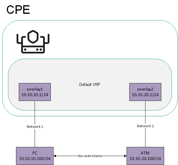
Network interfaces connected to different networks in the virtual default routing and forwarding table
To isolate Network 1 and Network 2, the overlay1 and overlay2 network interfaces must be added to different virtual routing and forwarding tables, which creates two segments (see the figure below).
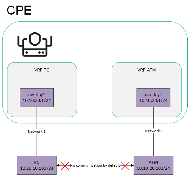
Network interfaces connected to different networks are in separate virtual default routing and forwarding tables
- Sending the 0.0.0.0/0 over BGP.
You can create a separate virtual routing and forwarding table for sending the 0.0.0.0/0 route between devices over BGP. The figure below shows a CPE device with the SD-WAN gateway (GW) role and a standard device. All CPE devices in the network are added to the default virtual routing and forwarding table.
If the SD-WAN gateway sends the 0.0.0.0/0 BGP route from overlay network interface 10.10.10.254/24 to overlay network interface 10.10.10.1/24, such a route cannot be used. This is the case because the default virtual routing and forwarding table already has 0.0.0.0/0 routes with a lower administrative distance for connecting to the controller and orchestrator.
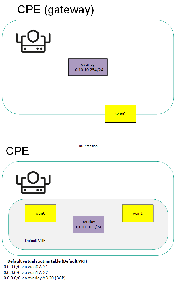
Sending the 0.0.0.0/0 route to a CPE device with the default virtual routing and forwarding table
To send route 0.0.0.0/0 over BGP through the overlay 10.10.10.254/24 network interface to overlay 10.10.10.1/24, you must create a separate table for the overlay 10.10.10.1/24 network interface and add BGP routes to it (see the figure below).

Sending the 0.0.0.0/0 route to a CPE device with a separate virtual routing and forwarding table for BGP routes
The table of virtual routing and forwarding tables is displayed in the CPE template and on the CPE device:
- To display the table of virtual routing and forwarding tables in a CPE template, go to the SD-WAN → CPE templates menu section, click the CPE template, and select the VRF tab.
- To display the table of virtual routing and forwarding tables on a CPE device, go to the SD-WAN → CPE menu section, click the CPE device, and select the VRF tab.
Information about virtual routing and forwarding tables is displayed in the following columns of the table:
- Name is the name of the virtual routing and forwarding table.
- Table is the ID of the virtual routing and forwarding table.
- Interfaces are network interfaces that have been added to the virtual routing and forwarding table.
Creating a virtual routing and forwarding table
You can create a virtual routing and forwarding table in a CPE template or on a CPE device. A virtual routing and forwarding table created in the CPE template is automatically created on all CPE devices that use this CPE template.
To create a virtual routing and forwarding table:
- Create a virtual routing and forwarding table in one of the following ways:
- If you want to create a virtual routing and forwarding table in a CPE template, go to the SD-WAN → CPE templates menu section, click the CPE template, and select the VRF tab.
- If you want to create a virtual routing and forwarding table on a CPE device, go to the SD-WAN → CPE menu section, click the CPE device, and select the VRF tab.
The table of virtual routing and forwarding tables is displayed.
- Click + VRF.
- This opens a window; in that window, in the Name field, enter the name of the virtual routing and forwarding table.
- In the Table field, enter the ID of the virtual routing and forwarding table. Range of values: 100 to 199.
- In the Interfaces drop-down list, select the created network interface that you want to add to the virtual routing and forwarding table. You cannot add the same network interface to multiple virtual routing and forwarding tables.
The network instance is added and displayed in the lower part of the window. You can add multiple network interfaces or delete a network interface. To delete a network interface, click Delete next to it.
If you added a network interface with a name in the 'overlay.<number>' format (for example, 'overlay.100') to the virtual routing and forwarding table, you must select the Enable automatically and Force IP, route, and gateway check boxes when creating or editing the network interface.
- Click + Create.
- Create a record in the orchestrator web interface for the system network interface:
- Select the Network settings tab.
The table of network interfaces is displayed.
- Click + Network interface.
- This opens a window; in that window, in the Alias field, enter the name of the virtual routing and forwarding table that you specified at step 3 of these instructions. Maximum length: 15 characters.
- If firewall zones are assigned to network interfaces in the virtual routing and forwarding table, and the CPE device firewall does not, by default, accept traffic packets forwarded between network interfaces and subnets, in the Zone drop-down list, select a firewall zone. The selected firewall zone must also be assigned to one of the network interfaces in the virtual routing and forwarding table.
- In the Interface name field, enter the name of the virtual routing and forwarding table that you specified at step 3 of these instructions. Maximum length: 256 characters.
- Select the Network settings tab.
- Click Create.
A record for the system network interface is created and displayed in the table.
- In the upper part of the settings area, click Save to save the settings of the CPE template or CPE device.
Modifying the virtual routing and forwarding table
You can edit a virtual routing and forwarding table in a CPE template or on a device. A virtual routing and forwarding table edited in the CPE template is automatically edited on all CPE devices that use this CPE template. You cannot edit a virtual routing and forwarding table that is inherited from a CPE template on a CPE device.
To edit a virtual routing and forwarding table:
- Edit a virtual routing and forwarding table in one of the following ways:
- If you want to edit a virtual routing and forwarding table in a CPE template, go to the SD-WAN → CPE templates menu section, click the CPE template, and select the VRF tab.
- If you want to edit a virtual routing and forwarding table on a CPE device, go to the SD-WAN → CPE menu section, click the CPE device, and select the VRF tab.
The table of virtual routing and forwarding tables is displayed.
- Click Edit next to the virtual routing and forwarding table that you want to edit.
- This opens a window; in that window, if necessary, edit the name and/or ID of the virtual routing and forwarding table, and add or delete network interfaces.
- Click Save.
The virtual routing and forwarding table is modified and updated in the table.
- In the upper part of the settings area, click Save to save the settings of the CPE template or CPE device.
Deleting a virtual routing and forwarding table
You can delete a virtual routing and forwarding table in a CPE template or on a CPE device. A virtual routing and forwarding table deleted in the CPE template is automatically deleted on all CPE devices that use this CPE template. You cannot delete a virtual routing and forwarding table that is inherited from a CPE template on a CPE device.
Deleted virtual routing and forwarding tables cannot be restored.
To delete a virtual routing and forwarding table:
- Delete a virtual routing and forwarding table in one of the following ways:
- If you want to delete a virtual routing and forwarding table in a CPE template, go to the SD-WAN → CPE templates menu section, click the CPE template, and select the VRF tab.
- If you want to delete a virtual routing and forwarding table on a CPE device, go to the SD-WAN → CPE menu section, click the CPE device, and select the VRF tab.
The table of virtual routing and forwarding tables is displayed.
- Click Delete next to the virtual routing and forwarding table that you want to delete.
- In the confirmation window, click Delete.
The virtual routing and forwarding table is deleted and is no longer displayed in the table.
- In the upper part of the settings area, click Save to save the settings of the CPE template or CPE device.
Monitoring traffic packet information using the NetFlow protocol
Kaspersky SD-WAN supports NetFlow versions 1, 5, and 9 for monitoring information about traffic packets on a CPE device.
To avoid configuring each CPE device individually, you can specify basic NetFlow settings in the NetFlow template and then apply the template to CPE devices when adding or manually registering them. If you edit a setting in a NetFlow template, the setting is automatically modified on all CPE devices that are using this NetFlow template. When you edit a setting on a CPE device, that setting becomes independent of the NetFlow template. When the same setting is edited in the NetFlow template, the change is not propagated to the CPE device.
When specifying basic NetFlow settings, you can specify up to four NetFlow collectors. If you want a CPE device to send information about traffic packets to NetFlow collectors, you must enable the NetFlow protocol on network interfaces. The NetFlow protocol can be enabled when creating or editing the network interface.
Managing NetFlow templates
To display the table of NetFlow templates, go to the SD-WAN → NetFlow templates section. One of the NetFlow templates is the default template, which means it is pre-selected when adding and manually registering a CPE device. By default, the Default NetFlow template is created on the administrator portal, which forms the basis for all other NetFlow templates you create. For tenants, you must manually create and assign the default NetFlow template on the self-service portal.
Information about NetFlow templates is displayed in the following columns of the table:
- ID is the ID of the NetFlow template.
- Name is the name of the NetFlow template.
- Usage indicates whether the NetFlow template is being used by CPE devices:
- Yes
- No
- Updated is the date and time when the CPE template settings were last modified.
- User is the name of the user which created the NetFlow template.
- Owner is the tenant to which the NetFlow template belongs.
The actions you can perform with the table are described in the Managing solution component tables instructions.
Creating a NetFlow template
To create a NetFlow template:
- In the menu, go to the SD-WAN → NetFlow templates section.
A table of NetFlow templates is displayed.
- In the upper part of the page, click + NetFlow template.
- This opens a window; in that window, enter the name of the NetFlow template.
- Click Create.
The NetFlow template is created and displayed in the table.
You need to configure the created NetFlow template. For a description of NetFlow template settings, see the instructions on how to configure general NetFlow settings.
Page top
Setting a default NetFlow template
You can set a NetFlow template as the default to have it preselected when adding or manually registering a CPE device.
To set a default NetFlow template:
- In the menu, go to the SD-WAN → NetFlow templates section.
A table of NetFlow templates is displayed.
- Click the NetFlow template that you want to make the default NetFlow template.
The settings area is displayed in the lower part of the page. You can expand the settings area to fill the entire page by clicking the expand icon
. - In the upper part of the settings area, under Actions, click Set as default template.
The NetFlow template is set as the default NetFlow template.
Page top
Exporting a NetFlow template
You can export a NetFlow template to subsequently import it into another NetFlow template.
To export a NetFlow template:
- In the menu, go to the SD-WAN → NetFlow templates section.
A table of NetFlow templates is displayed.
- Click the NetFlow template that you want to export.
The settings area is displayed in the lower part of the page. You can expand the settings area to fill the entire page by clicking the expand icon
. - In the upper part of the settings area, under Actions, click Export.
An archive in the TAR.GZ format is saved on your local device. The archive does not contain information about CPE devices using the NetFlow template.
Page top
Importing a NetFlow template
You can export a NetFlow template and subsequently import it into another NetFlow template. NetFlow template settings are specified in accordance with the settings of the imported NetFlow template. During import, you can select the settings that you want to leave unchanged. The NetFlow template into which you are importing another NetFlow template remains applied to CPE devices, but the settings of those CPE devices are not modified.
To import a NetFlow template:
- In the menu, go to the SD-WAN → NetFlow templates section.
A table of NetFlow templates is displayed.
- Click the NetFlow template that you want to export.
The settings area is displayed in the lower part of the page. You can expand the settings area to fill the entire page by clicking the expand icon
. - In the upper part of the settings area, under Actions, click Export.
An archive in the TAR.GZ format is saved on your local device. The archive does not contain information about CPE devices using the NetFlow template.
- Click the NetFlow template into which you want to import another NetFlow template.
The settings area is displayed in the lower part of the page. You can expand the settings area to fill the entire page by clicking the expand icon
. - In the upper part of the settings area, under Actions, click Import.
- This opens a window; in that window, clear the check boxes next to the NetFlow template settings that you want to leave unchanged after import.
- In the File field, specify the path to the TAR.GZ archive.
- Click Import.
NetFlow template settings are modified in accordance with the settings of the imported NetFlow template.
Page top
Cloning a NetFlow template
You can clone a NetFlow template to create an identical NetFlow template with a different name.
To clone a NetFlow template:
- In the menu, go to the SD-WAN → NetFlow templates section.
A table of NetFlow templates is displayed.
- Click the NetFlow template that you want to clone.
The settings area is displayed in the lower part of the page. You can expand the settings area to fill the entire page by clicking the expand icon
. - In the upper part of the settings area, under Actions, click Clone.
- This opens a window; in that window, enter the name of the new NetFlow template.
- Click Clone.
A copy of the NetFlow template with the new name is created and displayed in the table.
Page top
Viewing the usage of a NetFlow template
You can see which CPE devices are using the NetFlow template. If a NetFlow template is in use, it cannot be deleted.
To view NetFlow template usage:
- In the menu, go to the SD-WAN → NetFlow templates section.
A table of NetFlow templates is displayed.
- Click the NetFlow template for which you want to view usage information.
The settings area is displayed in the lower part of the page. You can expand the settings area to fill the entire page by clicking the expand icon
. - In the upper part of the settings area, under Actions, click Show usage.
This opens a window with a table of CPE devices that are using the NetFlow template.
Page top
Deleting a NetFlow template
You cannot delete a NetFlow template if it is being used by at least one CPE device. You need to look up the usage of the NetFlow template and make sure that it is not in use.
Deleted NetFlow templates cannot be restored.
To delete a NetFlow template:
- In the menu, go to the SD-WAN → NetFlow templates section.
A table of NetFlow templates is displayed.
- Click the NetFlow template that you want to delete.
The settings area is displayed in the lower part of the page. You can expand the settings area to fill the entire page by clicking the expand icon
. - In the upper part of the settings area, under Actions, click Delete.
- In the confirmation window, click Delete.
The NetFlow template is deleted and is no longer displayed in the table.
Page top
Basic NetFlow settings
You can specify basic NetFlow settings in a NetFlow template or on a CPE device. Basic NetFlow settings specified in the NetFlow template are automatically propagated to all CPE devices that use this NetFlow template.
To modify the basic NetFlow settings:
- Specify basic NetFlow settings in one of the following ways:
- If you want to edit basic NetFlow settings in a NetFlow template, go to the SD-WAN → NetFlow templates menu section and click the NetFlow template.
- If you want to edit the basic NetFlow settings on a CPE device, go to the SD-WAN → CPE menu section, click the CPE device, select the NetFlow tab, and select the Override check box.
Basic NetFlow settings are displayed.
- In the NetFlow drop-down list, select Enabled. The default value is Disabled.
- Specify the NetFlow collector:
- Under Collectors, click + Add.
- Under Host, enter the IPv4 address of the NetFlow collector.
- Under Port, enter the port number of the NetFlow collector. Range of values: 1 to 65,535.
The NetFlow collector is specified and displayed in the Collectors section. You can specify up to four NetFlow collectors or delete a NetFlow collector. To delete a NetFlow collector, click the delete icon
next to it. - In the Export version drop-down list, select the version of the NetFlow protocol:
- 1
- 5
- 9 (default)
- In the Tracking level drop-down list, select which traffic packet information the CPE device tracks:
- ETHER to track the following information:
- Source and destination IP addresses and ports
- Source and destination MAC addresses
- Outer VLAN tag
- Protocol being used
- FULL to track the source and destination IP addresses and ports, as well as the protocol being used. Default value.
- VLAN to track the following information:
- Source and destination IP addresses and ports
- Outer VLAN tag
- Protocol being used
- PROTO to track the source and destination IP addresses and the protocol being used.
- IP to track the source and destination IP addresses.
- ETHER to track the following information:
- In the Maximum flows field, enter the maximum number of traffic flows that the CPE device can simultaneously track. Range of values: 1 to 65,535. Default value:
8192.The higher the value, the higher the CPU load on the CPE device.
- In the Sampling rate field, specify how frequently the CPE device tracks the traffic packet information. For example, if you enter
10, the CPE device tracks information about every tenth packet of traffic. Range of values: 1 to 8192. Default value:1024.The lower the value, the more accurate the information and the higher the CPU load on the CPE device.
- In the Timeout maximum life (sec.) field, enter the maximum time in seconds for which the CPE device can track traffic flow information. To disable this feature, enter
0. Range of values: 1 to 9999. Default value:60. - In the Hop limit field, enter the maximum number of hops to NetFlow collectors. Range of values: 1 to 255. Default value:
64. - If you want the CPE device to track IPv6 traffic, in the Track IPv6 drop-down list, select Enabled. The default value is Disabled.
- In the upper part of the settings area, click Save to save the settings of the NetFlow template or CPE device.
If you want a CPE device to send information about traffic packets to NetFlow collectors, you must enable the NetFlow protocol on network interfaces. The NetFlow protocol can be enabled when creating or editing the network interface.
Page top
Changing the NetFlow template of a CPE Device
To change the NetFlow template of a CPE device:
- In the menu, go to the SD-WAN → CPE section.
A table of CPE devices is displayed.
- Click the CPE device for which you want to change the NetFlow template.
The settings area is displayed in the lower part of the page. You can expand the settings area to fill the entire page by clicking the expand icon
. By default, the Configuration tab is selected, which displays general information about the CPE device. This tab also displays the table of Out-of-band management tasks being performed by the orchestrator. - In the NetFlow template drop-down list, select a created NetFlow template.
- In the upper part of the settings area, click Save to save CPE device settings.
Diagnosing a CPE device
You can request diagnostic information and statistics, such as BGP, OSPF, and PIM protocol usage, from a CPE device. The diagnostic information returned in response to the request is displayed in the web interface of the orchestrator and, if necessary, can be downloaded as a TXT file.
Kaspersky SD-WAN also supports the following utilities for CPE device diagnostics:
- Ping is a utility for testing the connection between a CPE device and a specified IPv4 address. A report with the output of the utility is displayed in the orchestrator web interface.
- Traceroute is a utility for determining the route between a CPE device and a specified IPv4 address. A report with the output of the utility is displayed in the orchestrator web interface.
- Tcpdump is a utility for capturing traffic on a CPE device and writing this traffic to a report file. Capturing means a copy is made of the traffic, and the original traffic is relayed to its destination. The file with the captured traffic can be downloaded or deleted.
- Iperf is a utility for diagnosing network performance and writing the results to a report file. You can use the CPE device as an iperf server or as an iperf client. You can download or delete the network performance diagnostics file.
- Sweep is a utility for performing the following actions on a CPE device:
- Clearing the ARP cache
- Restarting the FRR (Free Range Routing) process
- Clearing the NAT session table
Running an utility is a task that the CPE device receives from the orchestrator; the task obeys the time period configured for the CPE device for sending REST API requests to the orchestrator. If you want the utilities to run sooner, you can enable interactive mode on the CPE device.
In interactive mode, the CPE device uses a shorter interval for sending REST API requests to the orchestrator. Interactive mode ends automatically when the specified duration has passed. You can specify the following interactive mode settings when configuring the connection of a CPE device to the orchestrator and controller:
- The period to wait until the CPE device sends another REST API request to the orchestrator in interactive mode
- The time after which the interactive mode is automatically disabled
Requesting diagnostic information
To request diagnostic information:
- In the menu, go to the SD-WAN → CPE section.
A table of CPE devices is displayed.
- Click the CPE device on which you want to request diagnostic information.
The settings area is displayed in the lower part of the page. You can expand the settings area to fill the entire page by clicking the expand icon
. By default, the Configuration tab is selected, which displays general information about the CPE device. This tab also displays the table of Out-of-band management tasks being performed by the orchestrator. - Select the Diagnostic information tab.
The diagnostic information request parameters are displayed.
- Click Request diagnostic information.
- In the Name drop-down list, select the type of diagnostic information you want to display:
- disk usage for information about the disk usage of the CPE device. Default value.
- dump-flows for information about OpenFlow flows.
- dump-groups for information about OpenFlow groups.
- ip addresses for information about IP addresses assigned to physical ports or virtual interfaces of the operating system of the CPE device.
- vrf data for information about virtual routing and forwarding tables.
- ip neighbors for information about the IP neighbors of the CPE device, obtained from the ARP table or using the Neighbor Discovery Protocol.
- ip routes for information about IPv4 and IPv6 routes.
- ip rules for information about routing rules.
- iptables for information about iptables.
- cpe log for the local log of the CPE device.
- ovs-ofctl show for information about the virtual switch.
- ovs-vsctl show for information about the link between the virtual switch and controllers.
- ovs-vsctl list controller for information about controllers specified for the virtual switch.
- show ip ospf for Information about the OSPF routing process.
- show ip ospf interface for information about OSPF interfaces.
- show ip ospf neighbor - information about OSPF neighbors.
- show ip ospf database for the OSPF database.
- bgp show ip route for information about BGP routes.
- show ip bgp for information about the BGP routing process.
- show ip bgp summary for brief information about the BGP routing process.
- top process for information about Linux processes.
- uptime for information about the CPE device uptime.
- time sync for information about time synchronization on the CPE device using an NTP server.
- netstat for information about network links that the CPE device has established.
- sdwan interfaces for information about SD-WAN interfaces.
- modems for information about modems.
- show bfd peers for information about BFD peers.
- netflow dump-flows for information about NetFlow flows.
- netflow statistics for information about the use of the NetFlow protocol.
- show bfd peers brief for brief information about BFD peers.
- show ip pim bsr for information about the current bootstrap router (BSR).
- show ip pim bsrp-info for information about the group-to-rp mapping received from the boostrap router.
- show ip pim interface for information about PIM interfaces. You can configure the PIM protocol when creating or editing a mutlicast interface.
- show ip pim interface traffic for information about PIM traffic.
- show ip pim join for information about multicast groups to which the CPE device is connected.
- show ip pim neighbor for information about PIM neighbors.
- show ip pim nexthop for information about the next hops of multicast groups.
- show ip pim rp-info for information about rendezvous points. You can specify rendezvous points when specifying basic PIM settings.
- show ip pim secondary for information about the backup PIM router.
- show ip pim state for information about the state of the PIM protocol.
- show ip pim statistics for Information about PIM protocol usage.
- show ip pim upstream for information about PIM sources.
- show ip igmp groups for information about IGMP groups.
- show ip igmp interface for information about IGMP interfaces. You can configure IGMP when creating or editing a mutlicast interface.
- show ip igmp interface detail for detailed information about IGMP interfaces.
- show ip igmp sources for information about IGMP sources.
- igmp statistics for information about IGMP usage.
- show ip multicast for information about the multicast routing process.
- show ip mroute for information about multicast routes.
- show ip mroute summary for brief information about multicast routes.
- vswitchd log for the log of the ovs-vswitchd process.
- firewall config for information about the firewall.
- sw version for the firmware version of the CPE device.
- vrrp stats for brief information about VRRP usage.
- vrrp data for information about VRRP usage.
- If you want to filter the displayed diagnostic information:
- In the Find line by pattern field, enter words that must be found in the lines of diagnostic information that you want to be displayed. Maximum length: 64 characters. If you want to display only lines that do not contain the words you entered, select the Select non-matching lines check box. This check box is cleared by default.
- In the Print N lines before and after field, enter the number of blank lines you want to display before and after each line of diagnostic information.
- If you want to download the file with diagnostic information, click Download file with latest data.
An TXT file is saved on your local device.
Enabling interactive mode
You can specify the following interactive mode settings when configuring the connection of a CPE device to the orchestrator and controller:
- The period to wait until the CPE device sends another REST API request to the orchestrator in interactive mode
- The time after which the interactive mode is automatically disabled
To enable interactive mode:
- In the menu, go to the SD-WAN → CPE section.
A table of CPE devices is displayed.
- Click the CPE device on which you want to enable interactive mode.
The settings area is displayed in the lower part of the page. You can expand the settings area to fill the entire page by clicking the expand icon
. By default, the Configuration tab is selected, which displays general information about the CPE device. This tab also displays the table of Out-of-band management tasks being performed by the orchestrator. - In the upper part of the settings area, click Enable interactive.
Interactive mode is enabled on the CPE device.
Page top
Running the ping utility
To run the ping utility:
- In the menu, go to the SD-WAN → CPE section.
A table of CPE devices is displayed.
- Click the CPE device on which you want to run the ping utility.
The settings area is displayed in the lower part of the page. You can expand the settings area to fill the entire page by clicking the expand icon
. By default, the Configuration tab is selected, which displays general information about the CPE device. This tab also displays the table of Out-of-band management tasks being performed by the orchestrator. - Select the Utilities tab.
By default, the Ping tab is selected, which displays the ping utility settings.
- In the Destination IP address field, enter the IPv4 address to which you the CPE device sends ICMP requests.
- If you want the CPE device to send ICMP requests from a certain created network interface, in the Source interface drop-down list, select the network interface.
- In the Count field, enter the number of ICMP requests that the CPE device sends. Range of values: 1 to 1,000,000. Default value:
5. - In the Timeout (sec.) field, enter the time in seconds after which the CPE device must receive an ICMP response to consider the request a success. Range of values: 1 to 3600. Default value:
2. - In the Size field, enter the size of the ICMP request in bytes. Range of values: 1 to 65,535. The default value is
56. - In the TTL field, enter the maximum number of hops for ICMP requests. Range of values: 1 to 255. Default value:
255. - In the Interval field, enter the interval in seconds for the CPE device to use when sending ICMP requests to the specified IPv4 address. Range of values: 1 to 300. Default value:
1. - Click Run.
The ping utility is run on the CPE device, and a report containing the output of the ping utility is displayed in the lower part of the settings area.
Page top
Running the traceroute utility
To run the traceroute utility:
- In the menu, go to the SD-WAN → CPE section.
A table of CPE devices is displayed.
- Click the CPE device on which you want to run the traceroute utility.
The settings area is displayed in the lower part of the page. You can expand the settings area to fill the entire page by clicking the expand icon
. By default, the Configuration tab is selected, which displays general information about the CPE device. This tab also displays the table of Out-of-band management tasks being performed by the orchestrator. - Select the Utilities → Traceroute tab.
The traceroute utility settings are displayed.
- In the Destination IP address field, enter the IPv4 address to which you the CPE device sends the series of ICMP requests.
- If you want the CPE device to send the series of ICMP requests from a certain created network interface, in the Source interface drop-down list, select the network interface.
- If you want the CPE device to use the DNS server to resolve IP addresses to domain names when creating the report with the output of the traceroute utility, select the Resolve DNS names check box. You can specify a DNS server when creating or editing a network interface. IP addresses that cannot be resolved to domain names are also displayed in the report. This check box is cleared by default.
- In the Probes timeout (sec.) field, enter the time in seconds after which the CPE device must receive a series of ICMP responses to consider the series of ICMP requests a success. Range of values: 1 to 30. Default value:
3. - In the Max hops field, enter the maximum number of hops for the series of ICMP requests. Range of values: 1 to 60. Default value:
10. - Click Run.
The traceroute utility is run on the CPE device, and a report containing the output of the traceroute utility is displayed in the lower part of the settings area.
Page top
Running the tcpdump utility
If you have previously run the tcpdump utility, a report file was generated with the captured traffic. When you run the utility again, that report file is overwritten. You can download the previous report file if you want to keep it.
The tcpdump utility puts additional load on the CPU of the CPE device.
To run the tcpdump utility:
- In the menu, go to the SD-WAN → CPE section.
A table of CPE devices is displayed.
- Click the CPE device on which you want to run the tcpdump utility.
The settings area is displayed in the lower part of the page. You can expand the settings area to fill the entire page by clicking the expand icon
. By default, the Configuration tab is selected, which displays general information about the CPE device. This tab also displays the table of Out-of-band management tasks being performed by the orchestrator. - Select the Utilities → Tcpdump tab.
The tcpdump utility settings are displayed.
- In the Capture interface drop-down list, select the created network interface on which you want to capture traffic.
- In the Direction drop-down list, select the direction of the traffic you want to capture:
- in to capture incoming traffic.
- out to capture outgoing traffic.
- in/out to capture both incoming and outgoing traffic. Default value.
- If you want the CPE device to use the DNS server to resolve IP addresses to domain names when creating the report file with the captured traffic, select the Resolve DNS names check box. You can specify a DNS server when creating or editing a network interface. IP addresses that cannot be resolved to domain names are also reflected in the report file. This check box is cleared by default.
- If you want to use a filter to capture traffic, in the Capture expression (tcpdump filter format) field, enter the syntax of the filter. Maximum length: 1024 characters. For example, you can use the following filters:
icmpto capture only ICMP traffic packets.host 1.2.3.4 and (port 80 or 443)to capture only traffic packets with IPv4 address 1.2.3.4 and source or destination TCP port 80 or 443.tcp[13] & 2 != 0to capture only TCP SYN traffic packets.
Detailed information about traffic filters can be obtained from the official tcpdump documentation.
- In the Maximum capture time (sec.) field, enter the time in seconds after which traffic capture stops. Range of values: 10 to 600. Default value:
30. - In the Max. captured packets field, enter the number of traffic packets that you want collected before traffic capture stops. Range of values: 1 to 10,000. Default value:
1000.Traffic capturing stops when the time specified in the Maximum capture time (sec.) field passes, or when the number of traffic packets specified in the Max. captured packets field is captured.
- Click Run.
The tcpdump utility is run on the CPE device, and a report file with the captured traffic is generated.
Page top
Running the iperf utility
If you have already run the iperf utility, a report file was generated with network performance diagnostics results. When you run the utility again, that report file is overwritten. You can download the previous report file if you want to keep it.
To run the iperf utility:
- In the menu, go to the SD-WAN → CPE section.
A table of CPE devices is displayed.
- Click the CPE device on which you want to run the iperf utility.
The settings area is displayed in the lower part of the page. You can expand the settings area to fill the entire page by clicking the expand icon
. By default, the Configuration tab is selected, which displays general information about the CPE device. This tab also displays the table of Out-of-band management tasks being performed by the orchestrator. - Select the Utilities → Iperf tab.
The iperf utility settings are displayed.
- Specify the mode in which you want to use the iperf utility on the CPE device by selecting one of the following options:
- Server to use the CPE device as an iperf server.
- Client to use the CPE device as an iperf client.
- If you chose the Server option, configure the iperf server:
- In the Port field, enter the TCP or UDP port number of the iperf server. Range of values: 1001 to 65,535. Default value:
7777. - In the Report interval (sec.) field, enter the interval in seconds for writing lines to the report file. Range of values: 0 to 60. Default value:
3. - If you do not want to create a report file with network performance diagnostics results, select the Do not report check box. This check box is cleared by default.
- Under Report format, select the format of the network performance diagnostics results in the report file:
- Kbit/sec (default)
- Mbit/sec
- Kbyte/sec
- Mbyte/sec
- In the Run server for (sec.) field, enter the duration in seconds for which you want the iperf server to run. Range of values: 60 to 3600. Default value:
300.
- In the Port field, enter the TCP or UDP port number of the iperf server. Range of values: 1001 to 65,535. Default value:
- If you chose the Client option, configure the iperf client:
- In the Server IP field, enter the IPv4 address of the iperf server to which the client connects.
- In the Port field, enter the TCP or UDP port number of the iperf server to which the client connects. Range of values: 1001 to 65,535. Default value:
7777. - In the Report interval (sec.) field, enter the interval in seconds for writing lines to the performance diagnostics report file. Range of values: 0 to 60. Default value:
3. - If you do not want to create a report file with network performance diagnostics results, select the Do not report check box. This check box is cleared by default.
- Under Report format, select the format of the network performance diagnostics results in the report file:
- Kbit/sec (default)
- Mbit/sec
- Kbyte/sec
- Mbyte/sec
- In the Run client for (sec.) field, enter the duration in seconds for which you want the iperf client to run. Range of values: 60 to 3600. Default value:
60. - Specify the port type of the iperf server by selecting one of the following options:
- TCP (default).
- UDP
- In the Client bitrate field, enter the bit rate of the iperf client in one of the following formats:
<bit rate in kbps>kor<bit rate in kbps>KFor example, if you enter
10000K, the bit rate is 10,000 kbps.<bit rate in Mbps>mor<bit rate in Mbps>MFor example, if you enter
10M, the bit rate is 10 Mbps.
- In the Test direction drop-down list, select the direction of traffic that you want to use for measuring network performance:
- client-server to use the traffic that the iperf client sends to the server. Default value.
- server-client to use the traffic that the iperf server sends to the client.
- bidirectional to use traffic that the iperf client sends to the server as well as the traffic that the iperf server sends to the client.
- If necessary, in the TCP windows size, bytes field, enter the TCP window size in bytes. If you do not specify a value for this parameter, the TCP window size is automatically detected.
- If necessary, in the TCP MSS, bytes field, enter the maximum TCP segment size in bytes.
- Click Run.
The iperf utility is run on the CPE device, and a report file with the network diagnostics results is generated.
To manage the report file, click Download results.
Page top
Running the sweep utility
You can use the sweep utility to clear the ARP cache, restart the Free Range Routing (FRR) process, and/or clear the NAT session table on a CPE device.
Restarting the FRR process and clearing the NAT session table may cause traffic transmission to stop for a few seconds.
To run the sweep utility:
- In the menu, go to the SD-WAN → CPE section.
A table of CPE devices is displayed.
- Click the CPE device on which you want to run the sweep utility.
The settings area is displayed in the lower part of the page. You can expand the settings area to fill the entire page by clicking the expand icon
. By default, the Configuration tab is selected, which displays general information about the CPE device. This tab also displays the table of Out-of-band management tasks being performed by the orchestrator. - Select the Utilities → Sweep tab.
The sweep utility settings are displayed.
- If you want to clear the ARP cache:
- Under Clear ARP-cache on interface, select the created network interface on which you want to clear the ARP cache. If you want to clear the ARP cache on all network interfaces, select All.
- Click Run.
The ARP cache is cleared on the CPE device.
- If you want to restart the FRR process, under Restart FRR (routing) process, click Run.
The FRR process is restarted on the CPE device.
- If you want to clear the NAT session table, under Clear NAT sessions table, click Run. You can configure NAT on a CPE device using a firewall.
The NAT session table is cleared on the CPE device.
Managing report files
Report files are generated from the output of the tcpdump and iperf utilities. To display the table of report files on a CPE device, go to the SD-WAN → CPE menu section, click the CPE device, and select the Utilities → Files tab. Information about report files is displayed in the following columns of the table:
- Type is the type of the report file.
- Created is the date and time when the report file was created.
The actions you can perform with the table are described in the Managing solution component tables instructions.
Downloading a report file
To download a report file:
- In the menu, go to the SD-WAN → CPE section.
A table of CPE devices is displayed.
- Click the CPE device from which you want to download the report file.
The settings area is displayed in the lower part of the page. You can expand the settings area to fill the entire page by clicking the expand icon
. By default, the Configuration tab is selected, which displays general information about the CPE device. This tab also displays the table of Out-of-band management tasks being performed by the orchestrator. - Select the Utilities → Files tab.
A table of report files is displayed.
- Click Download file next to the report file that you want to download.
An TXT file is saved on your local device.
Page top
Deleting a report file
Deleted report files cannot be restored.
To delete a report file:
- In the menu, go to the SD-WAN → CPE section.
A table of CPE devices is displayed.
- Click the CPE device on which you want to delete a report file.
The settings area is displayed in the lower part of the page. You can expand the settings area to fill the entire page by clicking the expand icon
. By default, the Configuration tab is selected, which displays general information about the CPE device. This tab also displays the table of Out-of-band management tasks being performed by the orchestrator. - Select the Utilities → Files tab.
A table of report files is displayed.
- Click Delete next to the report file that you want to delete.
- In the confirmation window, click Delete.
The report file is deleted and is no longer displayed in the table.
Page top
Running scheduled tasks on CPE devices
Kaspersky SD-WAN supports running scheduled tasks on CPE devices. Unlike standard tasks, scheduled tasks run at a specified time instead of immediately. You can use tags to group CPE devices on which you want to run a scheduled task.
Two types of scheduled tasks exist:
- Scheduling scripts on CPE devices.
- Scheduling firmware updates on manually selected CPE devices and on CPE devices with specified tags.
When you create a scheduled task, it uses the time zone of the virtual machine on which the orchestrator is deployed. For example, if you schedule a script to run on a CPE device at 2:00 p.m., the script runs at 2:00 p.m. in the time zone of the orchestrator, even if the time on the CPE device is 6:00 p.m.
We recommend taking into account the following special considerations when managing scheduled tasks:
- A 10-second inaccuracy is considered acceptable for the moment when the scheduled task is run.
- If multiple scheduled tasks exist, they run simultaneously. If the orchestrator cannot run all scheduled tasks simultaneously, they are run in the order they were created.
- Deleting a CPE template automatically deletes all scheduled tasks associated with it.
- Deleting a CPE device automatically deletes all scheduled tasks associated with it.
- When deleting a script associated with scheduled tasks, this action requires additional confirmation. If you confirm the action, the script is deleted and cannot be run within the created scheduled tasks.
You can manually run scheduled tasks that have not yet been run.
The table of scheduled tasks is displayed in the Scheduler section. Information about scheduled tasks is displayed in the following columns of the table:
- ID is the ID of the scheduled task.
- Name is the name of the scheduled task.
- User is the name of the user which created the scheduled task.
- Created is the date and time when the scheduled task was created.
- Status is the status of the scheduled task:
- Done means the scheduled task has been completed successfully.
- Error means an error occurred while running the scheduled task.
- Pending means the scheduled task is placed in the orchestrator database and is awaiting execution.
- Queued means the scheduled task is queued for execution.
- Running means the scheduled task is running.
- Scheduled is the date and time when the scheduled task was run.
The actions that you can perform with the table are described in the Managing solution component tables instructions.
Creating a scheduled task
To create a scheduled task:
- In the menu, go to the Scheduler section.
The table of scheduled tasks is displayed.
- In the upper part of the page, click + Delayed task.
- Specify the settings of the scheduled task. For a description of scheduled task settings, see the following instructions:
- Click Create.
The scheduled task is created and displayed in the table.
Page top
Manually running a scheduled task
To manually run a scheduled task:
- In the menu, go to the Scheduler section.
The table of scheduled tasks is displayed.
- To manually run an individual scheduled task:
- Click the scheduled task that you want to manually run.
The settings area is displayed in the lower part of the page. You can expand the settings area to fill the entire page by clicking the expand icon
. - In the upper part of the settings area, under Actions, click Run now.
- Click the scheduled task that you want to manually run.
- To manually run multiple scheduled tasks:
- Select check boxes next to scheduled tasks that you want to manually run.
- In the upper part of the table, click Actions → Run now.
- In the confirmation window, click Run now.
The scheduled tasks are completed, and their status in the Status column changes to Done.
Page top
Deleting a scheduled task
Deleted scheduled tasks cannot be restored.
To delete a scheduled task:
- In the menu, go to the Scheduler section.
The table of scheduled tasks is displayed.
- To delete an individual scheduled task:
- Click the scheduled task that you want to delete.
The settings area is displayed in the lower part of the page. You can expand the settings area to fill the entire page by clicking the expand icon
. - In the upper part of the settings area, under Actions, click Delete.
- Click the scheduled task that you want to delete.
- To delete multiple scheduled tasks:
- Select check boxes next to scheduled tasks that you want to delete.
- In the upper part of the table, click Actions → Delete.
- In the confirmation window, click Delete.
The scheduled tasks are deleted and are no longer displayed in the table.
Page top
IP address and subnet ranges for CPE devices
You can create ranges of IP addresses and subnets to centrally assign IPv4 addresses when creating or editing network interfaces of CPE devices. You can also use IP address ranges to centrally assign IPv4 addresses to router IDs of CPE devices when specifying basic BGP settings.
Managing IP address ranges
To display the table of IP address ranges, go to the SD-WAN → IPAM section. The IP Pool tab is selected by default. Information about IP address ranges is displayed in the following columns of the table:
- Name is the name of the IP address range.
- CIDR is the IPv4 prefix of the subnet in which the IP address range is located.
- IP range specifies the starting and ending values of the IP address range.
- Usage is the number of IP addresses in the range that have been assigned to network interfaces or router IDs of CPE devices.
The actions you can perform with the table are described in the Managing solution component tables instructions.
Creating a range of IP addresses
To create an IP address range:
- In the menu, go to the SD-WAN → IPAM section.
By default, the IP Pool tab is selected, displaying a table of IP address ranges.
- In the upper part of the page, click + IP Pool.
- This opens a window; in that window, in the Name field, enter the name of the IP address range. Maximum length: 32 characters.
- In the CIDR field, enter the IPv4 prefix of the subnet in which the IP address range is located.
- Specify a range of IP addresses. To do so, under IP range, click + Add and enter the starting and ending values of the IP address range.
The IP address range is specified and displayed in the IP range section. You can specify multiple IP address ranges or delete an IP address range. To delete an IP address range, click the delete icon
next to it. - Click Create.
The IP address range is created and displayed in the table.
Page top
Editing an IP address range
To change an IP address range:
- In the menu, go to the SD-WAN → IPAM section.
By default, the IP Pool tab is selected, displaying a table of IP address ranges.
- Click the IP address range that you want to edit.
- This opens a window; in that window, if necessary, edit the name and IPv4 prefix of the subnet containing the IP address range, and specify or delete the IP address ranges.
- In the upper part of the settings area, click Save.
The IP address range is modified and updated in the table.
Page top
Viewing the usage of an IP address range
You can see which CPE templates and CPE devices are using an IP address range. If an IP address range is in use, it cannot be deleted. You can also view information about IP addresses that have been assigned from the IP address range.
To view the usage of an IP address range:
- In the menu, go to the SD-WAN → IPAM section.
By default, the IP Pool tab is selected, displaying a table of IP address ranges.
- Click the IP address range for which you want to view usage information.
The settings area is displayed in the lower part of the page. You can expand the settings area to fill the entire page by clicking the expand icon
. By default, the Configuration tab is selected, displaying the settings of the IP address range. - View the usage of the IP address range in one of the following ways:
- If you want to see which CPE devices are using an IP address range, select the Usage → CPE tab.
A list of CPE devices that are using the IP address range is displayed.
- If you want to see which CPE templates are using an IP address range, select the Usage → Template tab.
A list of CPE templates that are using the IP address range is displayed.
- If you want to see which CPE devices are using an IP address range, select the Usage → CPE tab.
- If you want to view information about IP addresses that have been assigned from the IP address range, select the Leases tab.
A table of IP addresses assigned from the IP address range is displayed. Information about IP addresses is displayed in the following columns of the table:
- IP is the IP address that has been assigned from the IP address range.
- CPE is the CPE device to which the IP address is assigned.
- Type indicates whether the IP address is assigned to a network interface or router ID of a CPE device.
- Name is the name of the network interface to which the IP address is assigned. If an IP address has been assigned to the router ID of the CPE device, no value is displayed in this column.
- Tenant is the tenant to which the CPE device has been added.
The actions you can perform with the lists and table are described in the Managing solution component tables instructions.
Page top
Deleting IP address ranges
You cannot delete an IP address range if it is being used by at least one CPE template or CPE device. You need to look up the usage of the IP address range and make sure that it is not being used.
Deleted IP address ranges cannot be restored.
To delete IP address ranges:
- In the menu, go to the SD-WAN → IPAM section.
By default, the IP Pool tab is selected, displaying a table of IP address ranges.
- To delete an individual IP address range:
- Click the IP address range that you want to delete.
The settings area is displayed in the lower part of the page. You can expand the settings area to fill the entire page by clicking the expand icon
. By default, the Configuration tab is selected, displaying the settings of the IP address range. - In the upper part of the settings area, under Actions, click Delete.
- Click the IP address range that you want to delete.
- To delete multiple IP address ranges:
- Select check boxes next to IP address ranges that you want to delete.
- In the upper part of the table, click Actions → Delete.
- In the confirmation window, click Delete.
The IP address ranges are deleted and are no longer displayed in the table.
Page top
Managing subnet ranges
To display the table of subnet ranges, go to the SD-WAN → IPAM section and select the Subnet Pool tab. Information about subnet ranges is displayed in the following columns of the table:
- Name is the name of the subnet range.
- CIDR is the IPv4 prefix of the subnet range.
- Usage is the number of subnets that have been assigned to network interfaces.
The actions you can perform with the table are described in the Managing solution component tables instructions.
Creating a subnet range
To create a subnet range:
- In the menu, go to the SD-WAN → IPAM section.
By default, the IP Pool tab is selected, displaying a table of IP address ranges.
- Select the Subnet Pool tab.
A table of subnet ranges is displayed.
- In the upper part of the page, click + Subnet Pool.
- This opens a window; in that window, in the Name field, enter the name of the subnet range. Maximum length: 32 characters.
- In the Base CIDR field, enter the IPv4 prefix of the subnet range.
- In the Sub-prefix field, enter the length of the IPv4 prefix of subnets in the subnet range. Range of values: 0 to 32.
- Click Create.
The subnet range is created and displayed in the table.
Page top
Editing a subnet range
To edit a subnet range:
- In the menu, go to the SD-WAN → IPAM section.
By default, the IP Pool tab is selected, displaying a table of IP address ranges.
- Select the Subnet Pool tab.
A table of subnet ranges is displayed.
- Click the subnet range that you want to edit.
The settings area is displayed in the lower part of the page. You can expand the settings area to fill the entire page by clicking the expand icon
. By default, the Configuration tab is selected, displaying the settings of the subnet range. - This opens a window; in that window, if necessary, edit the following settings:
- Name of the subnet range
- IPv4 prefix of the subnet range
- IPv4 prefix length of subnets in the subnet range
- In the upper part of the settings area, click Save to save subnet range settings.
The subnet range is modified and updated in the table.
Page top
Viewing the usage of a subnet range
You can see which CPE templates and CPE devices are using a subnet range. If a subnet range is in use, it cannot be deleted. You can also view information about subnets that have been assigned from the subnet range.
To view the usage of a subnet range:
- In the menu, go to the SD-WAN → IPAM section.
By default, the IP Pool tab is selected, displaying a table of IP address ranges.
- Select the Subnet Pool tab.
A table of subnet ranges is displayed.
- Click the CPE template for which you want to view usage information.
The settings area is displayed in the lower part of the page. You can expand the settings area to fill the entire page by clicking the expand icon
. By default, the Configuration tab is selected, displaying the settings of the subnet range. - View the usage of the subnet range in one of the following ways:
- If you want to see which CPE devices are using a subnet range, select the Usage → CPE tab.
A list of CPE devices that are using the subnet range is displayed.
- If you want to see which CPE templates are using a subnet range, select the Usage → Template tab.
A list of CPE templates that are using the subnet range is displayed.
- If you want to see which CPE devices are using a subnet range, select the Usage → CPE tab.
- If you want to view information about subnets that have been assigned from the subnet range, select the Leases tab.
A table of subnets assigned from the subnet range is displayed. Information about subnets is displayed in the following columns of the table:
- CIDR is the IPv4 prefix of the subnet that was assigned from the subnet range.
- CPE is the CPE device to which an IPv4 address from the subnet subnet is assigned.
- Name is the name of the network interface to which an IPv4 address from the subnet is assigned.
- Tenant is the tenant to which the CPE device has been added.
The actions you can perform with the lists and table are described in the Managing solution component tables instructions.
Page top
Deleting subnet ranges
You cannot delete a subnet range if it is being used by at least one CPE template or CPE device. You need to look up the usage of the subnet range and make sure that it is not being used.
Deleted subnet ranges cannot be restored.
To delete subnet ranges:
- In the menu, go to the SD-WAN → IPAM section.
By default, the IP Pool tab is selected, displaying a table of IP address ranges.
- Select the Subnet Pool tab.
A table of subnet ranges is displayed.
- To delete an individual subnet range:
- Click the subnet range that you want to delete.
The settings area is displayed in the lower part of the page. You can expand the settings area to fill the entire page by clicking the expand icon
. By default, the Configuration tab is selected, displaying the settings of the subnet range. - In the upper part of the settings area, under Actions, click Delete.
- Click the subnet range that you want to delete.
- To delete multiple subnet ranges:
- Select check boxes next to subnet ranges that you want to delete.
- In the upper part of the table, click Actions → Delete.
- In the confirmation window, click Delete.
The subnet ranges are deleted and are no longer displayed in the table.
Page top
Managing the firewall
Kaspersky SD-WAN supports a firewall for filtering traffic packets on a CPE device. The firewall can accept, drop, or reject traffic packets. If a traffic packet is rejected, its sender receives an icmp-reject message. The firewall can apply each action to inbound and outbound traffic packets, as well as to traffic packets relayed between network interfaces and subnets of CPE devices. When specifying the basic firewall settings, you must set the default actions that the firewall performs with traffic packets.
To avoid configuring each CPE device individually, you can specify the firewall settings in the firewall template and then apply the template to CPE devices when adding or manually registering them. If you edit a setting in a firewall template, that setting is automatically modified on all CPE devices that are using the firewall template. When you edit a setting on a CPE device, that setting becomes independent of the firewall template. When the same setting is edited in the firewall template, the change is not propagated to the CPE device.
Firewall zones
You can add network interfaces and subnets to a firewall zone (hereinafter also referred to as 'zone') to receive, drop, or reject traffic packets transmitted through these network interfaces and subnets. When you create or edit a firewall zone, you need to specify the actions to be performed with traffic packets and, if necessary, add subnets. You can add network interfaces to a firewall zone when creating or editing a network interface.
If you want to allow transmitting traffic packets from one firewall zone to another, you can create a forwarding. When creating a forwarding, you must specify the inbound and outbound firewall zones.
You can create common firewall zones that multiple CPE devices can use, as well as firewall zones on an individual CPE device.
You cannot edit a common firewall zone because it can be used by a large number of CPE templates and CPE devices, and editing such a firewall zone would result in a mass update of all CPE templates and CPE devices that are using it, which would overload the orchestrator. If you want to edit the common firewall zone, you must create a new common firewall zone. To the created common firewall zone, you can add network interfaces and subnets that were added to the previous common firewall zone.
Firewall rules
You can create firewall rules to accept, drop, or reject traffic packets based on specified criteria. For example, you can create a firewall rule that rejects traffic packets with a specified source firewall zone.
If you want to specify the same IP addresses or subnets in multiple firewall rules, you need to create an IP set . When you create an IP set, you must specify whether the IP addresses and subnets belong to the source or the destination. You can specify the created IP set in firewall rule settings.
When a traffic packet is forwarded to a CPE device, the action specified in the settings of one of the firewall rules is performed on the traffic packet. If none of the firewall rules can be applied, the action specified in the settings of the firewall zone to which this packet was forwarded is applied to the traffic packet. If the traffic packet was not forwarded to any of the firewall zones, the default action that you specified while specifying basic firewall settings is applied to the traffic packet.
Network address translation
The firewall supports the following network address translation (NAT) mechanisms:
- DNAT rules can replace the following elements of traffic packets with the specified values:
- Destination IP addresses or prefixes
- Destination firewall zones
- Destination ports (Port Address Translation, PAT)
- SNAT rules can replace source IP addresses or prefixes of traffic packets with the specified values.
DNAT rules and SNAT rules are applied to traffic packets based on the specified criteria. For example, you can create a DNAT rule that replaces the destination IP address of TCP traffic packets.
Managing firewall zones
You can view the table of common firewall zones or the table of firewall zones on the CPE device:
- To display the table of common firewall zones, go to the SD-WAN → Firewall zones menu section.
- To display the table of firewall zones on a CPE device, go to the SD-WAN → CPE menu section, click the CPE device, and select the Firewall settings → Zones tab.
The following firewall zones are created by default:
- wan (WAN firewall zone) is the firewall zone for network interfaces that are connected to the WAN, for example, to the internet or the service provider network. Masquerading is enabled in the settings of the firewall WAN zone to replace the source IP address of outbound traffic packets from the firewall zone with the IP address assigned to the egress network interface.
- lan (LAN firewall zone) is the firewall zone for network interfaces that are connected to the LAN.
- mgmt (management firewall zone) is the firewall zone for the network interface that is used for passive monitoring of the CPE device by the Zabbix monitoring system, as well as for the SSH connection of the orchestrator to the CPE device.
You cannot delete the default firewall zones or create firewall zones with the same names.
When you upgrade Kaspersky SD-WAN from version 2.1 to 2.2, the following changes are made in the settings of all CPE templates:
- sdwan<0–4> network interfaces are automatically added to the WAN zone of the firewall.
- lan, br-lan, and overlay network interfaces are automatically added to the LAN zone of the firewall.
Information about common firewall zones is displayed in the following columns of the table:
- Name is the name of the firewall zone.
- Usage indicates whether the firewall zone is being used by firewall templates, CPE templates, and/or CPE devices:
- Yes
- No
- Author is the name of the user that created the firewall zone.
- Created is the date and time when the firewall zone was created.
The actions that you can perform with the table are described in the Managing solution component tables instructions.
Information about firewall zones on the CPE device is displayed in the following columns of the table:
- Name is the name of the firewall zone.
- Settings contains the actions that the firewall applies to traffic packets.
- Interfaces/Networks are network interfaces and subnets that have been added to the firewall zone.
Creating a firewall zone
You can create a common firewall zone or a firewall zone on the CPE device.
To create a firewall zone:
- Create a firewall zone in one of the following ways:
- If you want to create a common firewall zone, go to the SD-WAN → Firewall zones section and in the upper part of the page, click + Firewall zone.
- If you want to create a firewall zone on a CPE device, go to the SD-WAN → CPE menu section, click the CPE device, select the Firewall settings → Zones tab, select the Override check box, and click + Firewall zone.
A table of firewall zones is displayed.
- This opens a window; in that window, in the Name field, enter the name of the firewall zone. Maximum length: 255 characters.
- In the Input drop-down list, select the action that the firewall applies to inbound traffic packets:
- In the Output drop-down list, select the action that the firewall applies to outbound traffic packets:
- In the Forwarding drop-down list, select the action that the firewall applies to traffic packets forwarded between network interfaces and subnets:
- If you want to enable masquerading to replace the source IP address of outbound traffic packets from the firewall zone with the IP address assigned to the egress network interface:
- Clear the MSS clamp to PMTU check box if you do not want the firewall to limit the Maximum Segment Size (MSS) of traffic packets relayed through the firewall zone to the Path Maximum Transmission Unit (PMTU) value minus 40. The purpose of subtracting 40 is to exclude the size of the TCP header. This check box is selected by default.
- If you want the firewall to keep a log of traffic packets dropped in the firewall zone, select the Drops logging check box. If logs created on a CPE device are sent to a Syslog server, you can view the logs on that server. If logs created on the CPE device are stored locally, you can view the logs by requesting diagnostic information. This check box is cleared by default.
- If network interfaces are connected to L3 switches or routers, and you want to relay traffic packets from subnets of these L3 switches or routers, add a subnet to the firewall zone. To do so, under Networks, click + Add and enter an IPv4 subnet prefix.
The subnet is added and displayed under Networks. You can add multiple subnets or delete a subnet. To delete a subnet, click the delete icon
next to it. - Click Create.
The firewall zone is created and displayed in the table.
- If you have created a firewall zone on a CPE device, click Save in the upper part of the settings area to save the CPE device settings.
You must add network interfaces to the created firewall zone. You can do this when creating or editing a network interface. If you created a firewall zone on a CPE device, the network interfaces that you add to the firewall zone must be created on the same CPE device.
Page top
Editing the name of the firewall common zone
You can edit the name of the created common firewall zone. The process of editing the name of a firewall zone on a CPE device is described in the instructions on editing a firewall zone on the CPE device.
To edit the name of a common firewall zone:
- In the menu, go to the SD-WAN → Firewall zones section.
A table of firewall zones is displayed.
- Click the common firewall zone whose name you want to edit.
The settings area is displayed in the lower part of the page. You can expand the settings area to fill the entire page by clicking the expand icon
. - In the upper part of the settings area, under Actions, click Rename of Firewall zone.
- This opens a window; in that window, change the name of the common firewall zone.
- Click Rename.
The name of the common firewall zone is modified and updated in the table.
Page top
Cloning a firewall common zone
You can clone the created common firewall zone to create an identical common firewall zone with a different name. Cloning firewall zones on a CPE device is not supported.
To clone a common firewall zone:
- In the menu, go to the SD-WAN → Firewall zones section.
A table of firewall zones is displayed.
- Click the common firewall zone which you want to clone.
The settings area is displayed in the lower part of the page. You can expand the settings area to fill the entire page by clicking the expand icon
. - In the upper part of the settings area, under Actions, click Clone.
- This opens a window; in that window, enter a name for the new common firewall zone.
- Click Clone.
A copy of the common firewall zone with the new name is created and displayed in the table.
Page top
Viewing the usage of a firewall common zone
You can see which firewall templates, CPE templates, and CPE devices are using the created common zone. If the common firewall zone is in use, it cannot be deleted.
To view the usage of a common firewall zone:
- In the menu, go to the SD-WAN → Firewall zones section.
A table of firewall zones is displayed.
- Click the common firewall zone whose usage you want to view.
The settings area is displayed in the lower part of the page. You can expand the settings area to fill the entire page by clicking the expand icon
. - In the upper part of the settings area, under Actions, click Show usage.
This opens a window with a table of firewall templates, CPE templates, and CPE devices that are using the common firewall zone.
Page top
Editing a firewall zone on a CPE device
You can edit a firewall zone on a CPE device. You cannot edit a common firewall zone because it can be used by a large number of CPE templates and CPE devices, and editing such a firewall zone would result in a mass update of all CPE templates and CPE devices that are using it, which would overload the orchestrator. If you want to edit the common firewall zone, you must create a new common firewall zone. To the created common firewall zone, you can add network interfaces and subnets that were added to the previous common firewall zone.
To edit a firewall zone on a CPE device:
- In the menu, go to the SD-WAN → CPE section.
A table of CPE devices is displayed.
- Click the CPE device on which you want to edit the firewall zone.
The settings area is displayed in the lower part of the page. You can expand the settings area to fill the entire page by clicking the expand icon
. By default, the Configuration tab is selected, which displays general information about the CPE device. This tab also displays the table of Out-of-band management tasks being performed by the orchestrator. - Select the Firewall settings → Zones tab.
A table of firewall zones is displayed.
- Select the Override check box.
- Click Edit next to the firewall zone that you want to edit.
- This opens a window; in that window, if necessary, edit the firewall zone settings. For a description of the settings, see the instructions for creating a firewall zone.
- Click Save.
The firewall zone is modified and updated in the table.
- In the upper part of the settings area, click Save to save CPE device settings.
Deleting a firewall zone
You can delete a common firewall zone or a firewall zone on the CPE device.
Deleted firewall zones cannot be restored.
Deleting a firewall common zone
You cannot delete a common firewall zone if it is being used by at least one firewall template, CPE template, or CPE device. You must view the usage of the common firewall zone and make sure that it is not being used.
To delete a common firewall zone:
- In the menu, go to the SD-WAN → Firewall zones section.
A table of firewall zones is displayed.
- Click the common firewall zone which you want to delete.
The settings area is displayed in the lower part of the page. You can expand the settings area to fill the entire page by clicking the expand icon
. - In the upper part of the settings area, under Actions, click Delete.
- In the confirmation window, click Delete.
The common firewall zone is deleted and is no longer displayed in the table.
Deleting a firewall zone on a CPE device
To delete a firewall zone on a CPE device:
- In the menu, go to the SD-WAN → CPE section.
A table of CPE devices is displayed.
- Click the CPE device on which you want to delete the firewall zone.
The settings area is displayed in the lower part of the page. You can expand the settings area to fill the entire page by clicking the expand icon
. By default, the Configuration tab is selected, which displays general information about the CPE device. This tab also displays the table of Out-of-band management tasks being performed by the orchestrator. - Select the Firewall settings → Zones tab.
A table of firewall zones is displayed.
- Select the Override check box.
- Click Delete next to the firewall zone that you want to delete.
- In the confirmation window, click Delete.
The firewall zone is deleted and is no longer displayed in the table.
- In the upper part of the settings area, click Save to save CPE device settings.
Managing forwarding
The table of forwardings is displayed in the firewall template and on the CPE device:
- To display the table of forwardings in a firewall template, go to the SD-WAN → Firewall templates menu section, click the firewall template, and select the Zones forwarding tab.
- To display the table of forwardings on a CPE device, go to the SD-WAN → CPE menu section, click the CPE device, and select the Firewall settings → Zones forwarding tab.
Information about forwardings is displayed in the following columns of the table:
- From is the outbound firewall zone.
- To is the Inbound firewall zone.
Creating a forwarding
You can create a forwarding in a firewall template or on a CPE device. A forwarding created in a firewall template is automatically created on all CPE devices that use this firewall template.
To create a forwarding:
- Create a forwarding in one of the following ways:
- If you want to create a forwarding in a firewall template, go to the SD-WAN → Firewall templates menu section, click the firewall template, and select the Zones forwarding tab.
- If you want to create a forwarding on a CPE device, go to the SD-WAN → CPE menu section, click the CPE device, select the Firewall settings → Zones forwarding tab, and select the Override check box.
A table of forwardings is displayed.
- Click + Forwarding.
- This opens a window; in that window, in the From drop-down list, select a created outbound firewall zone.
- In the To drop-down list, select a created inbound firewall zone.
- Click Create.
The forwarding is created and displayed in the table.
- In the upper part of the settings area, click Save to save the settings of the firewall template or CPE device.
Deleting a forwarding
You can delete a forwarding in a firewall template or on a CPE device. A forwarding deleted in a firewall template is automatically deleted on all CPE devices that use this firewall template.
Deleted forwardings cannot be restored.
To delete a forwarding:
- Delete a forwarding in one of the following ways:
- If you want to delete a forwarding in a firewall template, go to the SD-WAN → Firewall templates menu section, click the firewall template, and select the Zones forwarding tab.
- If you want to delete a forwarding on a CPE device, go to the SD-WAN → CPE menu section, click the CPE device, select the Firewall settings → Zones forwarding tab, and select the Override check box.
A table of forwardings is displayed.
- Click Delete next to the forwarding that you want to delete.
- In the confirmation window, click Delete.
The forwarding is deleted and is no longer displayed in the table.
- In the upper part of the settings area, click Save to save the settings of the firewall template or CPE device.
Managing firewall templates
The table of firewall templates is displayed under SD-WAN → Firewall templates. One of the firewall templates is the default template, which means it is pre-selected when adding and manually registering a CPE device. By default, the Default firewall template is created, which forms the basis for other firewall templates you create. Information about firewall templates is displayed in the following columns of the table:
- Name is the name of the firewall template.
- Usage indicates whether the firewall template is being used by CPE devices:
- Yes
- No
- Owner is the name of the user that created the firewall template.
- Last update is the date and time when the firewall template settings were last modified.
The actions that you can perform with the table are described in the Managing solution component tables instructions.
Firewall template settings are displayed on the following tabs:
- Global settings contains basic settings of the firewall.
- Rules contains firewall rules.
- NAT contains network address translation settings. The following tabs are displayed on this tab:
- DNAT contains DNAT rules.
- SNAT contains SNAT rules.
- Zones forwarding contains forwardings between firewall zones.
- IP sets contains IP sets.
Creating a firewall template
To create a firewall template:
- Go to the SD-WAN → Firewall templates section.
A table of firewall templates is displayed.
- In the upper part of the page, click + Firewall template.
- This opens a window; in that window, enter the name of the firewall template.
- Click Create.
The firewall template is created and displayed in the table.
You need to configure the created firewall template. For a description of the firewall template tabs, see the Managing firewall templates section.
Page top
Setting the default firewall template
You can set a firewall template as the default to have it preselected when adding or manually registering a CPE device.
To set a default firewall template:
- Go to the SD-WAN → Firewall templates section.
A table of firewall templates is displayed.
- Click the firewall template that you want to make the default firewall template.
The settings area is displayed in the lower part of the page. You can expand the settings area to fill the entire page by clicking the expand icon
. By default, the Global settings tab is selected, which displays the main settings of the firewall template. - In the upper part of the settings area, under Actions, click Set as default template.
The firewall template is set as the default firewall template.
Page top
Exporting a firewall template
You can export a firewall template to subsequently import it into another firewall template.
To export a firewall template:
- Go to the SD-WAN → Firewall templates section.
A table of firewall templates is displayed.
- Click the firewall template that you want to export.
The settings area is displayed in the lower part of the page. You can expand the settings area to fill the entire page by clicking the expand icon
. By default, the Global settings tab is selected, which displays the main settings of the firewall template. - In the upper part of the settings area, under Actions, click Export.
An archive in the TAR.GZ format is saved on your local device. The archive does not contain information about CPE devices using the firewall template.
Page top
Importing a firewall template
You can export a firewall template and subsequently import it into another firewall template. Firewall template settings are specified in accordance with the settings of the imported firewall template. During import, you can select the tabs that you want to leave unchanged. A firewall template into which another firewall template is imported remains applied to CPE devices, but the settings of those CPE devices are not modified.
To import a firewall template:
- Go to the SD-WAN → Firewall templates section.
A table of firewall templates is displayed.
- Click the firewall template that you want to export.
The settings area is displayed in the lower part of the page. You can expand the settings area to fill the entire page by clicking the expand icon
. By default, the Global settings tab is selected, which displays the main settings of the firewall template. - In the upper part of the settings area, under Actions, click Export.
An archive in the TAR.GZ format is saved on your local device. The archive does not contain information about CPE devices using the firewall template.
- Click the firewall template into which you want to import another firewall template.
The settings area is displayed in the lower part of the page. You can expand the settings area to fill the entire page by clicking the expand icon
. By default, the Global settings tab is selected, which displays the main settings of the firewall template. - In the upper part of the settings area, under Actions, click Import.
- This opens a window; in that window, clear the check boxes next to the firewall template tabs that you want to leave unchanged after import.
- In the File field, specify the path to the TAR.GZ archive.
- Click Import.
Firewall template settings are modified in accordance with the settings of the imported firewall template.
Page top
Cloning a firewall template
You can clone a firewall template to create an identical firewall template with a different name.
To clone a firewall template:
- Go to the SD-WAN → Firewall templates section.
A table of firewall templates is displayed.
- Click the firewall template that you want to clone.
The settings area is displayed in the lower part of the page. You can expand the settings area to fill the entire page by clicking the expand icon
. By default, the Global settings tab is selected, which displays the main settings of the firewall template. - In the upper part of the settings area, under Actions, click Clone.
- This opens a window; in that window, enter the name of the new firewall template.
- Click Clone.
A copy of the firewall template with the new name is created and displayed in the table.
Page top
Viewing the usage of a firewall template
You can see which CPE devices are using the firewall template. If a firewall template is in use, it cannot be deleted.
To view the usage of a firewall template:
- Go to the SD-WAN → Firewall templates section.
A table of firewall templates is displayed.
- Click the firewall template for which you want to view usage information.
The settings area is displayed in the lower part of the page. You can expand the settings area to fill the entire page by clicking the expand icon
. By default, the Global settings tab is selected, which displays the main settings of the firewall template. - In the upper part of the settings area, under Actions, click Show associated CPEs.
This opens a window with a table of CPE devices that are using the firewall template.
Page top
Deleting a firewall template
You cannot delete a firewall template while it is in use. You need to look up the usage of the firewall template and make sure that it is not in use.
Deleted firewall templates cannot be restored.
To delete a firewall template:
- Go to the SD-WAN → Firewall templates section.
A table of firewall templates is displayed.
- Click the firewall template that you want to delete.
The settings area is displayed in the lower part of the page. You can expand the settings area to fill the entire page by clicking the expand icon
. By default, the Global settings tab is selected, which displays the main settings of the firewall template. - In the upper part of the settings area, under Actions, click Delete.
- In the confirmation window, click Delete.
The firewall template is deleted and is no longer displayed in the table.
Page top
Basic firewall settings
You can configure basic firewall settings in a firewall template or on a CPE device. Basic firewall settings specified in the firewall template are automatically propagated to all CPE devices that use this firewall template.
The firewall applies the actions specified in its basic settings to traffic packets. Traffic packets are affected by this if no firewall rules have been applied to them and they have not been forwarded to any of the firewall zones.
To specify the basic firewall settings:
- Specify basic firewall settings in one of the following ways:
- If you want to edit basic firewall settings in a firewall template, go to the SD-WAN → Firewall templates menu section and click the firewall template.
- If you want to edit basic firewall settings on a CPE device, go to the SD-WAN → CPE menu section, click the CPE device, select the Firewall settings → Global settings tab, and select the Override check box.
Basic firewall settings are displayed.
- If you want to disable SYN flood protection, clear the Syn-flood protection check box. This check box is selected by default. When SYN flood protection is enabled, a maximum of 25 traffic packets per second with the SYN, ACK, RST, and FIN flags can be sent to a CPE device.
- If you want the firewall to drop traffic packets marked as invalid by the conntrack function, select the Drop invalid packets check box. This check box is cleared by default.
- If you want to disable the DPI (Deep Packet Inspection) technology, clear the Enable DPI check box. This check box is selected by default. The DPI technology lets you create firewall rules that apply only to traffic packets of the specified application.
When the DPI technology is disabled, you cannot configure DPI marking, and firewall rules that use the DPI technology are automatically disabled.
- In the Default INPUT action drop-down list, select the action that the firewall applies to inbound traffic packets:
- In the Default OUTPUT action drop-down list, select the action that the firewall applies to outbound traffic packets:
- In the Default FORWARD action drop-down list, select the action that the firewall applies to traffic packets forwarded between network interfaces and subnets:
- In the upper part of the settings area, click Save to save the settings of the firewall template or CPE device.
Configuring DPI marking
Kaspersky SD-WAN supports creating firewall rules that are applied only to traffic packets of the specified application. You can specify the DPI marks that determine the traffic packets the rule is applied to. You cannot configure DPI marking if you disabled the DPI marking technology in basic firewall settings.
You can configure DPI marking in a firewall template or on a CPE device. DPI marking settings specified in the firewall template are automatically propagated to all CPE devices that use this firewall template.
To configure DPI marking:
- Configure DPI marking for the firewall is applied in one of the following ways:
- If you want to configure DPI marking in a firewall template, go to the SD-WAN → Firewall templates menu section, click the firewall template, and select the DPI marking tab.
- If you want to configure DPI marking on a CPE device, go to the SD-WAN → CPE menu section, click the CPE device, select the Firewall settings → DPI marking tab, and select the Override check box.
The DPI marking settings are displayed.
- Select the check boxes next to the DPI marks which you want to govern which firewall rules apply to which traffic packets.
- In the upper part of the settings area, click Save to save the settings of the firewall template or CPE device.
Managing firewall rules
The table of firewall rules is displayed in the firewall template and on the CPE device:
- To display the table of firewall rules in a firewall template, go to the SD-WAN → Firewall templates menu section, click the firewall template, and select the Rules tab.
- To display the table of firewall rules on a CPE device, go to the SD-WAN → CPE menu section, click the CPE device, and select the Firewall settings → Rules tab.
The following firewall rules are created by default:
- Allow-GENEVE allows the CPE device to receive GENEVE packets from the WAN firewall zone. GENEVE packets are encapsulated Kaspersky SD-WAN traffic.
- Allow-DHCP-Renew allows the CPE device to receive BOOTP packets from the WAN firewall zone, which is necessary for DHCP to work.
- Allow-IGMP allows the CPE device to receive IGMP packets from the WAN firewall zone, which is necessary for VRRP and multicast to work.
- The following firewall rules are temporarily disabled until full support for IPv6 becomes available in Kaspersky SD-WAN:
- Allow-DHCPv6 allows the CPE device to receive DHCPv6 packets from the WAN firewall zone, which is necessary for IPv6 to work.
- Allow-MLD allows the CPE device to receive MLD packets from the WAN firewall zone, which is necessary for IPv6 to work.
- Allow-ICMPv6-Input allows the CPE device to receive ICMPv6 packets from the WAN firewall zone, which is necessary for IPv6 to work.
- Allow-ICMPv6-Forward-From-Wan allows the CPE device to receive ICMPv6 packets from the WAN firewall zone, which packets are forwarded to the LAN firewall zone, which is necessary for IPv6 to work.
- Allow-ICMPv6-Forward-From-Lan allows the CPE device to receive ICMPv6 packets from the LAN firewall zone, which packets are forwarded to the WAN firewall zone, which is necessary for IPv6 to work.
- Explicit-deny-http(s)-on-wan blocks the CPE device from receiving TCP traffic packets with destination ports 80 or 443 to prevent access from the WAN firewall zone to the CPE device web server.
For the default firewall rules to work correctly, you need to add sd-wan<0–4> network interfaces to the WAN firewall zone. You can add network interfaces to a firewall zone when creating or editing a network interface.
Information about firewall rules is displayed in the following columns of the table:
- Name is the name of the firewall rule.
- Details contains criteria according to which the firewall applies the rule to traffic packets.
- Action is the action that the firewall rule applies to traffic packets.
Creating a firewall rule
You can create a firewall rule in a firewall template or on a CPE device. A firewall rule created in a firewall template is automatically created on all CPE devices that use this firewall template.
To create a firewall rule:
- Create a firewall rule in one of the following ways:
- If you want to create a firewall rule in a firewall template, go to the SD-WAN → Firewall templates menu section, click the firewall template, and select the Rules tab.
- If you want to create a firewall rule on a CPE device, go to the SD-WAN → CPE menu section, click the CPE device, select the Firewall settings → Rules tab, and select the Override check box.
A table of firewall rules is displayed.
- Click + Rule.
- This opens a window; in that window, in the Name field, enter the name of the firewall rule. Maximum length: 255 characters.
- In the Action drop-down list, select the action that the firewall rule applies to traffic packets:
- Specify the criteria according to which the firewall must apply the firewall rule to traffic packets:
- If you want to apply the firewall rule only to traffic packets with the specified source or destination IP addresses or subnets, in the IP set drop-down list, select a created IP set. If you select a value from this drop-down list, the Source IP and Destination IP blocks become unavailable.
- If you want to apply the firewall rule only to traffic packets with the specified version of source or destination IP addresses or subnets, in the IP version drop-down list, select one of the following options:
- IPv4
- IPv6
If you do not select a value, the firewall rule is applied to traffic packets with any version of source or destination IP addresses or subnets.
- If you want to apply the firewall rule only to traffic packets with the specified source firewall zone, in the Source zone drop-down list, select the created firewall zone.
- If you want to apply the firewall rule only to traffic packets with the specified destination firewall zone, in the Destination zone drop-down list, select a created firewall zone.
- If you want to apply the firewall rule only to traffic packets with the specified source IPv4 address or prefix, under Source IP, click + Add and enter an IPv4 address or prefix.
The IPv4 address or prefix is specified and displayed under Source IP. You can specify multiple IPv4 addresses or prefixes or delete an IPv4 address or prefix. To delete an IPv4 address or prefix, click the delete icon
next to it. - If you want to apply the firewall rule only to traffic packets with the specified destination IPv4 address prefix, under Destination IP, click + Add and enter an IPv4 address or prefix.
The IPv4 address or prefix is specified and displayed under Destination IP. You can specify multiple IPv4 addresses or prefixes or delete an IPv4 address or prefix. To delete an IPv4 address or prefix, click the delete icon
next to it. - If you want to apply the firewall rule only to traffic packets of the specified protocol, select a protocol in the Protocol drop-down list. When you select an option in this drop-down list, the DPI protocol drop-down list becomes unavailable.
With TCP or UDP selected, if you want to apply the firewall rule only to traffic packets with the specified source and/or destination ports:
- In the Source port field, enter a source port number or a range of source port numbers.
- In the Destination port field, enter a destination port number or a range of destination port numbers.
Range of values: 0 to 65,535. The format of the port number range is
<first value>-<last value>. For example, you can enter10or10-15. - If you want to apply the firewall rule only to traffic packets of the specified application, select an application in the DPI protocol drop-down list.
Traffic is attributed to applications using the DPI technology, which places additional load on the CPU of the CPE device.
You can specify the DPI marks that determine the traffic packets the rule is applied to. If you disabled the DPI technology when specifying the basic settings of the firewall, the firewall rule is automatically disabled.
- Click Create.
The firewall rule is created and displayed in the table.
- In the upper part of the settings area, click Save to save the settings of the firewall template or CPE device.
By default, the firewall rule is disabled. You must enable the firewall rule to have it applied to traffic packets.
Page top
Configuring the order of firewall rules
Firewall rules are applied to traffic packets in descending order, starting with the first firewall rule at the top of the table. By default, firewall rules are displayed in the table in the order of creation. The earlier a firewall rule was created, the higher it is displayed in the table.
You can configure the order in which firewall rules are applied in a firewall template or on a CPE device. The order in which firewall rules are applied, which is specified in the firewall template, is automatically propagated to all CPE devices that use this firewall template.
To configure the order in which firewall rules are applied:
- Edit the order in which firewall rules are applied in one of the following ways:
- If you want to configure the order in which firewall rules are applied in a firewall template, go to the SD-WAN → Firewall templates menu section, click the firewall template, and select the Rules tab.
- If you want to configure the order in which firewall rules are applied on a CPE device, go to the SD-WAN → CPE menu section, click the CPE device, select the Firewall settings → Rules tab, and select the Override check box.
A table of firewall rules is displayed.
- Configure the order in which firewall rules are applied by clicking the Up and Down buttons next to them.
- In the upper part of the settings area, click Save to save the settings of the firewall template or CPE device.
Enabling or disabling a firewall rule
By default, firewall rules are created in a disabled state. You must enable the firewall rule to have it applied to traffic packets.
You can enable or disable a firewall rule in a firewall template or on a CPE device. A firewall rule enabled or disabled in a firewall template is automatically enabled or disabled on all CPE devices that use this firewall template.
To enable or disable a firewall rule:
- Enable or disable a firewall rule in one of the following ways:
- If you want to enable or disable a firewall rule in a firewall template, go to the SD-WAN → Firewall templates menu section, click the firewall template, and select the Rules tab.
- If you want to enable or disable a firewall rule on a CPE device, go to the SD-WAN → CPE menu section, click the CPE device, select the Firewall settings → Rules tab, and select the Override check box.
A table of firewall rules is displayed.
- Click Enable or Disable next to the firewall rule that you want to enable or disable.
The firewall rule is enabled or disabled.
- In the upper part of the settings area, click Save to save the settings of the firewall template or CPE device.
Editing a firewall rule
You can edit a firewall rule in a firewall template or on a CPE device. A firewall rule modified in a firewall template is automatically modified on all CPE devices that use this firewall template.
To edit a firewall rule:
- Edit a firewall rule in one of the following ways:
- If you want to edit a firewall rule in a firewall template, go to the SD-WAN → Firewall templates menu section, click the firewall template, and select the Rules tab.
- If you want to edit a firewall rule on a CPE device, go to the SD-WAN → CPE menu section, click the CPE device, select the Firewall settings → Rules tab, and select the Override check box.
A table of firewall rules is displayed.
- Click Edit next to the firewall rule that you want to edit.
- This opens a window; in that window, if necessary, edit the firewall rule settings. For a description of the settings, see the instructions for creating a firewall rule.
- Click Save.
The firewall rule is modified and updated in the table.
- In the upper part of the settings area, click Save to save the settings of the firewall template or CPE device.
Deleting a firewall rule
You can delete a firewall rule in a firewall template or on a CPE device. A firewall rule deleted in a firewall template is automatically deleted on all CPE devices that use this firewall template.
Deleted firewall rules cannot be restored.
To delete a firewall rule:
- Delete a firewall rule in one of the following ways:
- If you want to delete a firewall rule in a firewall template, go to the SD-WAN → Firewall templates menu section, click the firewall template, and select the Rules tab.
- If you want to delete a firewall rule on a CPE device, go to the SD-WAN → CPE menu section, click the CPE device, select the Firewall settings → Rules tab, and select the Override check box.
A table of firewall rules is displayed.
- Click Delete next to the firewall rule that you want to delete.
- In the confirmation window, click Delete.
The firewall rule is deleted and is no longer displayed in the table.
- In the upper part of the settings area, click Save to save the settings of the firewall template or CPE device.
Managing IP sets
The table of IP sets is displayed in the firewall template and on the CPE device:
- To display the table of IP sets in a firewall template, go to the SD-WAN → Firewall templates menu section, click the firewall template, and select the IP sets tab.
- To display the table of IP sets on a CPE device, go to the SD-WAN → CPE menu section, click the CPE device, and select the Firewall settings → IP sets tab.
Information about IP sets is displayed in the following columns of the table:
- Name is the name of the IP set.
- Match indicates whether the IP set is associated with the source or the destination of traffic packets, and whether the set contains IP addresses or subnets.
- Entries are IP addresses or subnets that have been added to the IP set.
Creating an IP set
You can create an IP set in a firewall template or on a CPE device. An IP set created in a firewall template is automatically created on all CPE devices that use this firewall template.
To create an IP set:
- Create an IP set in one of the following ways:
- If you want to create an IP set in a firewall template, go to the SD-WAN → Firewall templates menu section, click the firewall template, and select the IP sets tab.
- If you want to create an IP set on a CPE device, go to the SD-WAN → CPE menu section, click the CPE device, select the Firewall settings → IP sets tab, and select the Override check box.
A table of IP sets is displayed.
- Click + IP set.
- This opens a window; in that window, in the Name field, enter the name of the IP set. Maximum length: 255 characters.
- In the Direction drop-down list, select whether the IP set is associated with the source or the destination of traffic packets:
- Match source if the IP set contains source IP addresses or subnets.
- Match destination if the IP set contains destination IP addresses or subnets.
- In the Type drop-down list, select whether the set contains IP addresses or subnets.
- Set of subnets if the IP set contains subnets.
- Set of IPs if the IP set contains IP addresses.
- If in the Type drop-down list, you selected Set of subnets, specify a subnet. To do so, under Entries list, click + Add and enter an IPv4 prefix. You can specify ranges of IPv4 prefix octets using square brackets, for example, 192.[165-168].2.0/24.
The subnet is specified and displayed under Entries list. You can specify multiple subnets or delete a subnet. To delete a subnet, click the delete icon
next to it. - If in the Type drop-down list, you selected Set of IPs, specify an IP address. To do so, under Entries list, click + Add and enter an IPv4 address. You can specify ranges of IPv4 address octets using square brackets, for example, 192.[165-168].2.0.
The IP address is specified and displayed in the Entries list section. You can specify multiple IP addresses or delete an IP address. To delete an IP address, click the delete icon
next to it. - Click Create.
The IP set is created and displayed in the table.
- In the upper part of the settings area, click Save to save the settings of the firewall template or CPE device.
Disabling or enabling an IP set
You can disable or enable an IP set in a firewall template or on a CPE device. An IP set enabled or disabled in a firewall template is automatically enabled or disabled on all CPE devices that use this firewall template.
To disable or enable an IP set:
- Disable or enable an IP set in one of the following ways:
- If you want to enable or disable an IP set in a firewall template, go to the SD-WAN → Firewall templates menu section, click the firewall template, and select the IP sets tab.
- If you want to enable or disable an IP set on a CPE device, go to the SD-WAN → CPE menu section, click the CPE device, select the Firewall settings → IP sets tab, and select the Override check box.
A table of IP sets is displayed.
- Click Disable or Enable next to the IP set that you want to disable or enable.
The IP set is disabled or enabled.
- In the upper part of the settings area, click Save to save the settings of the firewall template or CPE device.
Editing an IP set
You can edit an IP set in a firewall template or on a CPE device. An IP set modified in a firewall template is automatically modified on all CPE devices that use this firewall template.
To edit an IP set:
- Edit an IP set in one of the following ways:
- If you want to edit an IP set in a firewall template, go to the SD-WAN → Firewall templates menu section, click the firewall template, and select the IP sets tab.
- If you want to edit an IP set on a CPE device, go to the SD-WAN → CPE menu section, click the CPE device, select the Firewall settings → IP sets tab, and select the Override check box.
A table of IP sets is displayed.
- Click Edit next to the IP set that you want to edit.
- This opens a window; in that window, if necessary, edit the IP set settings. For a description of the settings, see the instructions for creating an IP set.
- Click Save.
The IP set is modified and updated in the table.
- In the upper part of the settings area, click Save to save the settings of the firewall template or CPE device.
Deleting an IP set
You can delete an IP set in a firewall template or on a CPE device. An IP set deleted in a firewall template is automatically deleted on all CPE devices that use this firewall template.
Deleted IP sets cannot be restored.
To delete an IP set:
- Delete an IP set in one of the following ways:
- If you want to delete an IP set in a firewall template, go to the SD-WAN → Firewall templates menu section, click the firewall template, and select the IP sets tab.
- If you want to delete an IP set on a CPE device, go to the SD-WAN → CPE menu section, click the CPE device, select the Firewall settings → IP sets tab, and select the Override check box.
A table of IP sets is displayed.
- Click Delete next to the IP set that you want to delete.
- In the confirmation window, click Delete.
The IP set is deleted and is no longer displayed in the table.
- In the upper part of the settings area, click Save to save the settings of the firewall template or CPE device.
Managing DNAT rules
The table of DNAT rules is displayed in the firewall template and on the CPE device:
- To display the table of DNAT rules in a firewall template, go to the SD-WAN → Firewall templates menu section, click the firewall template, and select the NAT → DNAT tab.
- To display the table of DNAT rules on a CPE device, go to the SD-WAN → CPE menu section, click the CPE device, and select the Firewall settings → NAT → DNAT tab.
Information about DNAT rules is displayed in the following columns of the table:
- Name is the name of the DNAT rule.
- Incoming contains the criteria according to which the firewall applies the DNAT rule to traffic packets:
- Redirect to is the destination IP address and port of traffic packets after the DNAT rule is applied.
Creating a DNAT rule
You can create a DNAT rule in a firewall template or on a CPE device. A DNAT rule created in a firewall template is automatically created on all CPE devices that use this firewall template.
To create a DNAT rule:
- Create a DNAT rule in one of the following ways:
- If you want to create a DNAT rule in a firewall template, go to the SD-WAN → Firewall templates menu section, click the firewall template, and select the NAT → DNAT tab.
- If you want to create a DNAT rule on a CPE device, go to the SD-WAN → CPE menu section, click the CPE device, select the Firewall settings → NAT → DNAT tab, and select the Override check box.
A table of DNAT rules is displayed.
- Click + DNAT.
- This opens a window; in that window, in the Name field, enter the name of the DNAT rule. Maximum length: 255 characters.
- Specify the criteria according to which the firewall must apply the DNAT rule to traffic packets:
- In the Protocol drop-down list, select the protocol of traffic packets to which the firewall applies the DNAT rule:
- IP
- TCP
- UDP
- # for custom or non-standard protocol. If you select this value, in the displayed Protocol number field, enter the protocol number in accordance with the IANA standard.
- In the Destination IP field, enter the destination IPv4 address or prefix of traffic packets to which the firewall applies the DNAT rule.
- If you want to apply the DNAT rule only to traffic packets with the specified source firewall zone, in the Source zone drop-down list, select a created firewall zone.
- If in the Protocol drop-down list, you selected TCP or UDP, and you want to apply the DNAT rule only to traffic packets with the specified destination port, enter the port number in the Destination port field. Range of values: 1 to 65,535.
- If you want to apply the DNAT rule only to traffic packets with the specified source IPv4 address or prefix, in the Source IP field, enter an IPv4 address or prefix.
- In the Protocol drop-down list, select the protocol of traffic packets to which the firewall applies the DNAT rule:
- Specify how the DNAT rule modifies traffic packets:
- In the Destination IP field, enter a new IPv4 destination address or prefix.
- In the Destination zone drop-down list, select the new destination firewall zone.
- If in the Protocol drop-down list, you selected TCP or UDP, and you want to change the destination port number of traffic packets, enter a new port number in the Destination port field. Range of values: 1 to 65,535.
- Click Create.
The DNAT rule is created and displayed in the table.
- In the upper part of the settings area, click Save to save the settings of the firewall template or CPE device.
Configuring the order of DNAT rules
DNAT rules are applied to traffic packets in descending order, starting with the first DNAT rule at the top of the table. By default, DNAT rules are displayed in the table in the order of creation. The earlier a DNAT rule was created, the higher it is displayed in the table.
You can configure the order in which DNAT rules are applied in a firewall template or on a CPE device. The order in which DNAT rules are applied, which is specified in the firewall template, is automatically propagated to all CPE devices that use this firewall template.
To configure the order in which DNAT rules are applied:
- Edit the order in which the DNAT rules are applied in one of the following ways:
- If you want to configure the order in which DNAT rules are applied in a firewall template, go to the SD-WAN → Firewall templates menu section, click the firewall template, and select the NAT → DNAT tab.
- If you want to configure the order in which DNAT rules are applied on a CPE device, go to the SD-WAN → CPE menu section, click the CPE device, select the Firewall settings → NAT → DNAT tab, and select the Override check box.
A table of DNAT rules is displayed.
- Configure the order in which DNAT rules are applied by clicking the Up and Down buttons next to it.
- In the upper part of the settings area, click Save to save the settings of the firewall template or CPE device.
Disabling or enabling a DNAT rule
You can disable or enable a DNAT rule in a firewall template or on a CPE device. A DNAT rule enabled or disabled in a firewall template is automatically enabled or disabled on all CPE devices that use this firewall template.
To disable or enable a DNAT rule:
- Disable or enable a DNAT rule in one of the following ways:
- If you want to disable or enable a DNAT rule in a firewall template, go to the SD-WAN → Firewall templates menu section, click the firewall template and in the displayed settings area, select the NAT → DNAT tab.
- If you want to disable or enable a DNAT rule on a CPE device, go to the SD-WAN menu section → CPE, click the CPE device, in the displayed settings area, select the Firewall settings → NAT → DNAT tab and select the Override check box.
A table of DNAT rules is displayed.
- Click Disable or Enable next to the DNAT rule that you want to disable or enable.
The DNAT rule is disabled or enabled.
- In the upper part of the settings area, click Save to save the settings of the firewall template or CPE device.
Editing a DNAT rule
You can edit a DNAT rule in a firewall template or on a CPE device. A DNAT rule modified in a firewall template is automatically modified on all CPE devices that use this firewall template.
To edit a DNAT rule:
- Edit a DNAT rule in one of the following ways:
- If you want to edit a DNAT rule in a firewall template, go to the SD-WAN → Firewall templates menu section, click the firewall template, and select the NAT → DNAT tab.
- If you want to edit a DNAT rule on a CPE device, go to the SD-WAN → CPE menu section, click the CPE device, select the Firewall settings → NAT → DNAT tab, and select the Override check box.
A table of DNAT rules is displayed.
- Click Edit next to the DNAT rule that you want to edit.
- This opens a window; in that window, if necessary, edit the DNAT rule settings. For a description of the settings, see the instructions for creating a DNAT rule.
- Click Save.
The DNAT rule is modified and updated in the table.
- In the upper part of the settings area, click Save to save the settings of the firewall template or CPE device.
Deleting a DNAT rule
You can delete a DNAT rule in a firewall template or on a CPE device. A DNAT rule deleted in a firewall template is automatically deleted on all CPE devices that use this firewall template.
Deleted DNAT rules cannot be restored.
To delete a DNAT rule:
- Delete a DNAT rule in one of the following ways:
- If you want to delete a DNAT rule in a firewall template, go to the SD-WAN → Firewall templates menu section, click the firewall template, and select the NAT → DNAT tab.
- If you want to delete a DNAT rule on a CPE device, go to the SD-WAN → CPE menu section, click the CPE device, select the Firewall settings → NAT → DNAT tab, and select the Override check box.
A table of DNAT rules is displayed.
- Click Delete next to the DNAT rule that you want to delete.
- In the confirmation window, click Delete.
The DNAT rule is deleted and is no longer displayed in the table.
- In the upper part of the settings area, click Save to save the settings of the firewall template or CPE device.
Managing SNAT rules
The table of SNAT rules is displayed in the firewall template and on the CPE device:
- To display the table of SNAT rules in a firewall template, go to the SD-WAN → Firewall templates menu section, click the firewall template, and select the NAT → SNAT tab.
- To display the table of SNAT rule groups on a CPE device, go to the SD-WAN → CPE menu section, click the device, select the Firewall settings → NAT → SNAT tab, and select the Override check box.
Information about SNAT rules is displayed in the following table columns:
- Name is the name of the SNAT rule.
- Outgoing are criteria according to which the firewall applies the SNAT rule to traffic packets.
- Action is the action that the SNAT rule applies to traffic packets.
Creating a SNAT rule
You can create a SNAT rule in a firewall template or on a CPE device. A SNAT rule created in a firewall template is automatically created on all CPE devices that use this firewall template.
To create a SNAT rule:
- Create a SNAT rule in one of the following ways:
- If you want to create a SNAT rule in a firewall template, go to the SD-WAN → Firewall templates menu section, click the firewall template, and select the NAT → SNAT tab.
- If you want to create a SNAT rule on a CPE device, go to the SD-WAN → CPE menu section, click the CPE device, select the Firewall settings → NAT → SNAT tab, and select the Override check box.
A table of SNAT rules is displayed.
- Click + SNAT.
- This opens a window; in that window, in the Name field, enter the name of the SNAT rule. Maximum length: 255 characters.
- Specify the criteria according to which the firewall must apply the SNAT rule to traffic packets:
- In the Protocol drop-down list, select the protocol of traffic packets to which the firewall applies the SNAT rule:
- In the Destination zone drop-down list, select the created destination firewall zone of traffic packets to which the firewall applies the SNAT rule.
- If you want to apply the SNAT rule only to traffic packets with the specified source IPv4 address or prefix, in the Source IP field, enter an IPv4 address or prefix.
- If you want to apply the SNAT rule only to traffic packets with the specified destination IPv4 address or prefix, in the Destination IP field, enter an IPv4 address or prefix.
- In the Action drop-down list, select SNAT.
- In the SNAT IP field, enter a new source IP address or prefix that the SNAT rule specifies for traffic packets.
- Click Create.
The SNAT rule is created and displayed in the table.
- In the upper part of the settings area, click Save to save the settings of the firewall template or CPE device.
Configuring the order of SNAT rules
SNAT rules are applied to traffic packets in descending order, starting with the first SNAT rule at the top of the table. By default, SNAT rules are displayed in the table in the order of creation. The earlier a SNAT rule was created, the higher it is displayed in the table.
You can configure the order in which SNAT rules are applied in a firewall template or on a CPE device. The order in which SNAT rules are applied, which is specified in the firewall template, is automatically propagated to all CPE devices that use this firewall template.
To configure the order in which SNAT rules are applied:
- Edit the order in which the SNAT rules are applied in one of the following ways:
- If you want to configure the order in which SNAT rules are applied in a firewall template, go to the SD-WAN → Firewall templates menu section, click the firewall template, and select the NAT → SNAT tab.
- If you want to configure the order in which SNAT rules are applied on a CPE device, go to the SD-WAN → CPE menu section, click the CPE device, select the Firewall settings → NAT → SNAT tab, and select the Override check box.
A table of SNAT rules is displayed.
- Configure the order in which SNAT rules are applied by clicking the Up and Down buttons next to it.
- In the upper part of the settings area, click Save to save the settings of the firewall template or CPE device.
Disabling or enabling a SNAT rule
You can disable or enable a SNAT rule in a firewall template or on a CPE device. A SNAT rule enabled or disabled in a firewall template is automatically enabled or disabled on all CPE devices that use this firewall template.
To disable or enable a SNAT rule:
- Disable or enable a SNAT rule in one of the following ways:
- If you want to enable or disable a SNAT rule in a firewall template, go to the SD-WAN → Firewall templates menu section, click the firewall template, and select the NAT → SNAT tab.
- If you want to enable or disable a SNAT rule on a CPE device, go to the SD-WAN → CPE menu section, click the CPE device, select the Firewall settings → NAT → SNAT tab, and select the Override check box.
A table of SNAT rules is displayed.
- Click Disable or Enable next to the SNAT rule that you want to disable or enable.
The SNAT rule is disabled or enabled.
- In the upper part of the settings area, click Save to save the settings of the firewall template or CPE device.
Editing a SNAT rule
You can edit a SNAT rule in a firewall template or on a CPE device. A SNAT rule modified in a firewall template is automatically modified on all CPE devices that use this firewall template.
To edit a SNAT rule:
- Edit a SNAT rule in one of the following ways:
- If you want to edit a SNAT rule in a firewall template, go to the SD-WAN → Firewall templates menu section, click the firewall template, and select the NAT → SNAT tab.
- If you want to edit a SNAT rule on a CPE device, go to the SD-WAN → CPE menu section, click the CPE device, select the Firewall settings → NAT → SNAT tab, and select the Override check box.
A table of SNAT rules is displayed.
- Click Edit next to the SNAT rule that you want to edit.
- This opens a window; in that window, if necessary, edit the SNAT rule settings. For a description of the settings, see the instructions for creating a SNAT rule.
- Click Save.
The SNAT rule is modified and displayed in the table.
- In the upper part of the settings area, click Save to save the settings of the firewall template or CPE device.
Deleting a SNAT rule
You can delete a SNAT rule in a firewall template or on a CPE device. A SNAT rule deleted in a firewall template is automatically deleted on all CPE devices that use this firewall template.
Deleted SNAT rules cannot be restored.
To delete a SNAT rule:
- Delete a SNAT rule in one of the following ways:
- If you want to delete a SNAT rule in a firewall template, go to the SD-WAN → Firewall templates menu section, click the firewall template, and select the NAT → SNAT tab.
- If you want to delete a SNAT rule on a CPE device, go to the SD-WAN → CPE menu section, click the CPE device, select the Firewall settings → NAT → SNAT tab, and select the Override check box.
A table of SNAT rules is displayed.
- Click Delete next to the SNAT rule that you want to delete.
- In the confirmation window, click Delete.
The SNAT rule is deleted and is no longer displayed in the table.
- In the upper part of the settings area, click Save to save the settings of the firewall template or CPE device.
Changing the firewall template of a CPE device
Editing a CPE device firewall template may result in loss of communication with other CPE devices, as well as the loss of relayed traffic packets.
To change the firewall template of a CPE device:
- In the menu, go to the SD-WAN → CPE section.
A table of CPE devices is displayed.
- Click the CPE device for which you want to change the firewall template.
The settings area is displayed in the lower part of the page. You can expand the settings area to fill the entire page by clicking the expand icon
. By default, the Configuration tab is selected, which displays general information about the CPE device. This tab also displays the table of Out-of-band management tasks being performed by the orchestrator. - In the Firewall template drop-down list, select a created firewall template.
- In the upper part of the settings area, click Save to save CPE device settings.
Managing network services and virtualization of network functions
Network services
Network services relay traffic over the network and apply network functions to it, such as WAN optimization, shaping, and traffic protection. Each network service has a topology that you build using a graphical design tool. You can add components to the topology and connect them to each other.
You can build a topology in a network service template and then assign that network service template to a tenant. Components added to the template topology are automatically assigned to the tenant together with the network service template. A tenant can create and deploy network services, if necessary, using assigned network service templates, and edit network services that are already deployed.
You can use network services to deploy SD-WAN instances. The network service for deploying SD-WAN instances is called the SD-WAN network service (SD-WAN service).
An example of a network service topology is shown in the figure below.

Network service topology
Network function virtualization
Network function virtualization (NFV) lets you use virtualized storage, compute resources, and networks to provide network functions and combine these into network services.
You can deploy virtual network functions (VNF) and physical network functions (PNF) in network services. The difference between virtual and physical network functions is that the orchestrator does not manage the lifecycle of physical network functions. Third-party network functions are supported.
Kaspersky SD-WAN complies with the architecture specified in the ETSI NFV MANO specification (NFV Management and Network Orchestration), which defines the following main functional components:
- Orchestrator.
- .
- .
- The Zabbix monitoring system monitors the status of virtual and physical network functions and notifies the orchestrator when a network function needs to be restored or scaled.
- The NFV infrastructure consists of physical resources such as hardware storage, servers, and network devices.
- .
The figure below shows the relations between the solution components and the NFV infrastructure. Components of external solutions are marked in white, Kaspersky SD-WAN components are marked in green, and the red lines are connections between components.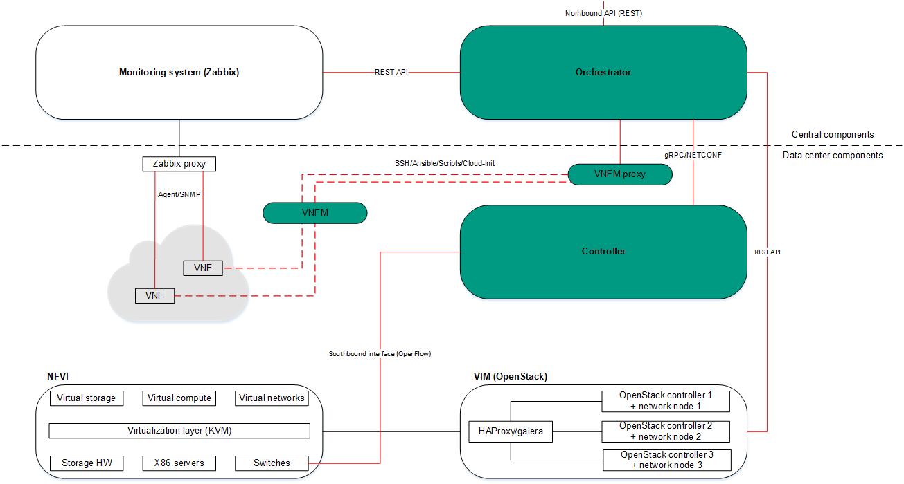
NFV infrastructure
Managing network service templates
A list of network service templates is displayed on the administrator portal in the Infrastructure section, in the Catalog pane on the Templates tab.
Creating a network service template
To create a network service template:
- In the menu, go to the Catalog section.
The network service management page is displayed.
- In the upper part of the page, click + Template.
The graphical design tool for building the topology is displayed.
- Add network service components to the topology:
- Drag network server components from the Catalog pane into the graphical design tool. The pane displays the following network service components:
- Network service templates — when you add a network service template to a topology, the topology is constructed in accordance with the network service template. You can add multiple network service templates to the topology.
- Shared network services — you must add a shared network service to the topology of network services that you want to connect to the shared network service. You can specify a brief description of the shared network service.
- Virtual and physical network functions. The actions that you can perform on virtual and physical network functions are described in the Managing virtual network functions and Managing physical network functions sections.
- Drag and drop links from the Links tab into the graphical design tool. The following links are displayed on this tab:
- P2P is the Point-to-Point transport service (P2P service). You can configure a P2P service.
- P2M is the Point-to-Multipoint transport service (P2M service). You can configure a P2M service.
- M2M is a Multipoint-to-Multipoint transport service (M2M service). You can configure an M2M service.
The remaining links are relevant to network communication at the VIM level and are established between VNFs hosted by the OpenStack cloud platform:
- OS shared is the shared network through which the shared network service connects to network services. You can configure a shared network.
- OS vRouter is the virtual L3 router. You can configure a virtual router.
- OS VLAN is the VLAN for transmitting tagged L2 traffic of the 802.1Q standard You can configure a VLAN.
- OS VXLAN is a VXLAN for tunneling. You can configure a VXLAN.
- OS flat is the flat network for transmitting untagged L2 traffic You can configure a flat network.
- Select the UNI tab and drag CPE device UNIs to the graphical design tool. The tab displays two components, UNI and WAN. Both components designate abstract UNIs that the tenant must replace with real UNIs when creating or editing a network service. The WAN component refers to UNIs that connect to the WAN.
You can configure a UNI in the topology.
The components are added to the topology and displayed in the graphical design tool.
- Drag network server components from the Catalog pane into the graphical design tool. The pane displays the following network service components:
- Connect the network service components added to the topology to each other:
- Click the link to which you want to connect a network service component.
- Click Add leaf to connect a network service component with the leaf role to the link. If you clicked a P2M service, you can click Add root to connect a network service component with the root role to the link.
- Click the network service component that you want to connect to the link. If you clicked a network function or shared network service, select the port to connect the link to in the displayed window.
The network service component is connected to the link, and a line is displayed between them in the topology. For example, the figure below shows the VLAN to which a virtual network function is connected.
- If you want to assign backup UNIs:
A backup UNI can be assigned only for UNIs which are connected to at least one link.
- Click the UNI for which you want to assign a backup UNI.
- Click Reserve.
- Click the UNI that you want to use as the backup.
The UNI is designated as the backup UNI, and a dotted line is displayed between the UNI, the backup UNI, and the link to which the UNI is connected. For example, in the figure below, the WAN is the backup interface for the UNI.
- If you want to remove a network service component from the topology, click the component, then click Delete.
The network service component is removed from the topology and is no longer displayed in the graphical design tool.
- If you want to horizontally align the topology, click Arrange.
- If you do not want to hide the descriptions of the added network service components in the topology, clear the Description check box. This check box is selected by default.
- In the Name field, enter the name of the network service.
- In the upper part of the graphical design tool, click Save.
The network service template is created and displayed in the Catalog pane, on the Templates tab.
Page top
Editing a network service template
When you edit a network service template, the changes are not applied to network services that have already been created and deployed using the network service template.
To edit a network service template:
- In the menu, go to the Catalog section.
The network service management page is displayed.
- In the Catalog pane, select the Templates tab.
A list of network service templates is displayed.
- Click the network service template that you want to edit.
The graphical design tool for building the topology is displayed.
- Edit the settings of the network service template. For a description of the settings, see the instructions for creating a network service template.
- In the upper part of the graphical design tool, click Save.
The network service template is modified and updated in the Templates tab.
Page top
Deleting a network service template
Deleted network service templates cannot be restored.
To delete a network service template:
- In the menu, go to the Catalog section.
The network service management page is displayed.
- In the Catalog pane, select the Templates tab.
A list of network service templates is displayed.
- Click the delete icon next to the network service template that you want to delete.
- In the confirmation window, click Delete.
The network service template is deleted and is no longer displayed in the Templates tab.
Page top
Managing network services
The list of network services is displayed on the self-service portal in the Infrastructure section, on the Network services pane. Before managing network services, you must log in to the tenant's self-service portal.
Creating a network service
To create a network service:
- In the menu, go to the Catalog section.
The network service management page is displayed.
- In the upper part of the Network services pane, click + Network service.
The graphical design tool for building the topology is displayed.
- Add network service components to the topology:
- Drag network server components from the Catalog pane into the graphical design tool. The pane displays the following network service components:
- Network service templates — when you add a network service template to a topology, the topology is constructed in accordance with the network service template. You can add multiple network service templates to the topology.
- Shared network services — you must add a shared network service to the topology of network services that you want to connect to the shared network service. You can specify a brief description of the shared network service.
- Virtual and physical network functions. The actions that you can perform on virtual and physical network functions are described in the Managing virtual network functions and Managing physical network functions sections.
- Drag and drop links from the Links tab into the graphical design tool. The following links are displayed on this tab:
- P2P is the Point-to-Point transport service (P2P service). You can configure a P2P service.
- P2M is the Point-to-Multipoint transport service (P2M service). You can configure a P2M service.
- M2M is a Multipoint-to-Multipoint transport service (M2M service). You can configure an M2M service.
The remaining links are relevant to network communication at the VIM level and are established between VNFs hosted by the OpenStack cloud platform:
- OS shared is the shared network through which the shared network service connects to network services. You can configure a shared network.
- OS vRouter is the virtual L3 router. You can configure a virtual router.
- OS VLAN is the VLAN for transmitting tagged L2 traffic of the 802.1Q standard You can configure a VLAN.
- OS VXLAN is a VXLAN for tunneling. You can configure a VXLAN.
- OS flat is the flat network for transmitting untagged L2 traffic You can configure a flat network.
- Select the UNI tab and drag CPE device UNIs to the graphical design tool. If you are using a network service template, you must replace the abstract UNIs in the topology with real UNIs. Abstract UNIs can be designated by two components, UNI and WAN. The WAN component refers to UNIs that connect to the WAN.
You can configure a UNI.
- Drag network server components from the Catalog pane into the graphical design tool. The pane displays the following network service components:
- Connect the network service components added to the topology to each other:
- Click the link to which you want to connect a network service component.
- Click Add leaf to connect a network service component with the leaf role to the link. If you clicked a P2M service, you can click Add root to connect a network service component with the root role to the link.
- Click the network service component that you want to connect to the link. If you clicked a network function or shared network service, select the port to connect the link to in the displayed window.
The network service component is connected to the link, and a line is displayed between them in the topology. For example, the figure below shows the VLAN to which a virtual network function is connected.
- If you want to assign backup UNIs:
A backup UNI can be assigned only for UNIs which are connected to at least one link.
- Click the UNI for which you want to assign a backup UNI.
- Click Reserve.
- Click the UNI that you want to use as the backup.
The UNI is designated as the backup UNI, and a dotted line is displayed between the UNI, the backup UNI, and the link to which the UNI is connected. For example, in the figure below, the WAN is the backup interface for the UNI.
- If you want to remove a network service component from the topology, click the component, then click Delete.
The network service component is removed from the topology and is no longer displayed in the graphical design tool.
- If you want to horizontally align the topology, click Arrange.
- If you do not want to hide the descriptions of the added network service components in the topology, clear the Description check box. This check box is selected by default.
- In the Name field, enter the name of the network service.
- Finish creating the network service in one of the following ways:
- To save the network service, click Save.
- To save and deploy the network service, click Deploy.
The network service is created and displayed in Network services pane. If you clicked Deploy, the deployment of the network service begins, which may take several minutes. You can interrupt the deployment by clicking Abort deploy.
Editing a network service
To edit a network service:
- In the menu, go to the Catalog section.
The network service management page is displayed.
- In the Network services pane, select the network service that you want to edit.
The graphical design tool for building the topology is displayed.
- In the upper part of the graphical design tool, click Edit.
- If necessary, edit the settings of the network service. For a description of the settings, see the instructions for creating a network service.
- Finish editing the network service in one of the following ways:
- If you are editing a network service that is not deployed, do one of the following:
- To save the network service, click Save.
- To save and deploy the network service, click Deploy.
- If you are editing a deployed network service, click Deploy changes to deploy the modified network service.
- If you are editing a network service that is not deployed, do one of the following:
The network service is modified and updated in Network services pane. If you clicked Deploy or Deploy changes, deployment begins, which may take several minutes. You can interrupt the deployment by clicking Abort deploy.
Page top
Deploying a network service
If a virtual network function deployed on a uCPE device is added to the network service topology and there is connectivity between the orchestrator and the uCPE device, this network service is deployed when connectivity is restored.
To deploy a network service:
- In the menu, go to the Catalog section.
The network service management page is displayed.
- In the Network services pane, select the network service that you want to deploy.
The graphical design tool for building the topology is displayed.
- In the upper part of the graphical design tool, click Edit.
- Click Deploy.
This starts the deployment of the network service, which may take several minutes. You can interrupt the deployment by clicking Abort deploy.
Checking the consistency of a network service
The consistency check allows verifying that the components are added to the network service topology actually exist.
To check the consistency of a network service:
- In the menu, go to the Catalog section.
The network service management page is displayed.
- In the Network services pane, click the settings icon → Check consistency next to the network service whose consistency you want to check.
- In the confirmation window, click Confirm.
This begins the consistency check of the network service.
Page top
Redeploying a network service
Redeploying a network service may result in short-term interruptions or temporary inoperability. When planning redeployment activities, we recommend taking into account your organization's circumstances to minimize the disruptions.
To redeploy a network service:
- In the menu, go to the Catalog section.
The network service management page is displayed.
- In the Network services pane, click the settings icon → Redeploy next to the network service that you want to redeploy.
- In the confirmation window, click Confirm.
This starts the redeployment of the network service, which may take several minutes. You can interrupt the deployment by clicking Abort deploy.
Page top
Disabling or enabling auto-healing for a network service
The Zabbix server monitors network service components and sends a REST API request to the orchestrator whenever a problem is detected. If the auto-healing functionality is enabled for the network service, the orchestrator initiates auto-healing for components with problems. By default, this functionality is enabled.
To disable or enable auto-healing for a network service:
- In the menu, go to the Catalog section.
The network service management page is displayed.
- In the Network services pane, click the settings icon → Disable Auto-Healing or Enable Auto-Healing next to the network service for which you want to disable or enable auto-healing.
Auto-healing is disabled or enabled for the network service.
You can perform auto-healing of virtual network functions or their VDUs even if auto-healing is disabled for the network service.
Page top
Viewing the network service log
To view the log of a network service:
- In the menu, go to the Catalog section.
The network service management page is displayed.
- In the Network services pane, click the settings icon → Open log next to the network service whose log you want to view.
The page with the network service log is displayed.
Page top
Deleting a network service
Deleted network services cannot be restored.
To delete a network service:
- In the menu, go to the Catalog section.
The network service management page is displayed.
- In the Network services pane, click the settings icon → Delete next to the network service that you want to delete.
- In the confirmation window, click Delete.
The network service is deleted and is no longer displayed in the Network services pane.
Page top
Scenario: Deploying a virtual network function
You can deploy a virtual network function for a tenant in a network service. The lifecycle of virtual network functions is managed by an orchestrator. To deploy virtual network functions, you need the OpenStack cloud platform.
For example, you can deploy a virtual network function at the central office of your organization to protect user traffic that is transmitted between CPE devices.
Virtual network function deployment involves the following steps:
- Preparing a VNF package
Prepare the VNF package that you want to deploy, and then upload the VNF package to the orchestrator web interface. If necessary, you can enable protection of VNF and PNF packages against substitution before uploading the VNF package to the orchestrator web interface.
- Ensuring network connectivity between the orchestrator and the OpenStack cloud platform
Ensure network connectivity between the virtual machine or physical server where the orchestrator is deployed and the OpenStack cloud platform.
- Assigning the virtual network function to a tenant
Use one of the following methods to assign the virtual network function to the tenant for which you want to deploy it:
- If you want to deploy a virtual network function using a network service template:
- Add the virtual network function to the topology when creating or editing a network service template.
- If necessary, configure the topology of the network service template and the virtual network function. For a description of what you can do with virtual network functions, see the Managing virtual network functions section.
- Assign the network service template to a tenant.
- If you want to deploy a virtual network function without a network service template, assign the virtual network function to the tenant.
- If you want to deploy a virtual network function using a network service template:
- Logging in to the tenant self-service portal
- Deploying the virtual network function
Do the following:
- Add the virtual network function to the topology when creating or editing a network service in one of the following ways:
- If you want to deploy a virtual network function using a network service template, add the network service template to the topology.
- If you want to deploy a virtual network function without a network service template, add the virtual network function to the topology.
- If necessary, configure the topology of the network service and the virtual network function. For a description of what you can do with virtual network functions, see the Managing virtual network functions section.
- Deploy the virtual network function using one of the following methods:
- If you added the virtual network function to the topology while creating the network service, deploy the network service.
- If you added the virtual network function to the topology while editing a network service, deploy the modified network service.
- Add the virtual network function to the topology when creating or editing a network service in one of the following ways:
The virtual network function is deployed.
Page top
Scenario: Deploying a physical network function
You can deploy a physical network function for a tenant in a network service. As physical network functions, you can use dedicated hardware as well as virtual entities created using third-party virtualization environments. The orchestrator does not manage the lifecycle of physical network functions.
For example, you can deploy a physical network function at the central office of your organization to protect user traffic that is transmitted between CPE devices.
Physical network function deployment involves the following steps:
- Preparing the PNF package
Prepare the PNF package that you want to deploy, and then upload the PNF package to the orchestrator web interface. If necessary, you can enable protection of VNF and PNF packages against substitution before uploading the PNF package to the orchestrator web interface.
- Ensuring network connectivity between the orchestrator and the physical network function
Ensure network connectivity between the virtual machine or physical server on which the orchestrator is deployed and the dedicated hardware or virtual entity on which you want to deploy the physical network function.
- Assigning the physical network function to a tenant
Use one of the following methods to assign the physical network function to the tenant for which you want to deploy it:
- If you want to deploy a physical network function using a network service template:
- Add the physical network function to the topology when creating or editing a network service template.
- If necessary, configure the topology of the network service template and the physical network function. For a description of what you can do with physical network functions, see the Managing physical network functions section.
- Assign the network service template to a tenant.
- If you want to deploy a physical network function without a network service template, assign the physical network function to the tenant.
- If you want to deploy a physical network function using a network service template:
- Logging in to the tenant self-service portal
- Deploying a physical network function
Do the following:
- Add the physical network function to the topology when creating or editing a network service in one of the following ways:
- If you want to deploy a physical network function using a network service template, add the network service template to the topology.
- If you want to deploy a physical network function without a network service template, add the physical network function to the topology.
- If necessary, configure the topology of the network service and the physical network function. For a description of what you can do with physical network functions, see the Managing physical network functions section.
- Deploy the physical network function using one of the following methods:
- If you added the physical network function to the topology while creating the network service, deploy the network service.
- If you added the physical network function to the topology while editing a network service, deploy the modified network service.
- Add the physical network function to the topology when creating or editing a network service in one of the following ways:
The physical network function is deployed.
Page top
Managing VNF and PNF packages
A VNF or PNF package is a ZIP archive in which you must place the following components to deploy a network function and manage its lifecycle:
- The VNF/PNF descriptor, a file with parameters of the network function.
- The /image directory, which contains virtual machine images in the QCOW format for deploying the virtual network function. This directory is not included in the PNF package.
- The /scripts directory, which contains scripts for deploying and managing the network function.
- logo.png, the icon of the network function. This component is optional.
- description-file.pdf, technical documentation or specification of the network function. This component is optional.
You must upload the VNF or PNF package to the orchestrator web interface to add a virtual or physical network function to the topology when managing a network service template or network service.
Configuring the VNF descriptor
Specify the settings of the virtual network function in a VNF descriptor in YAML or XML format, then add the VNF descriptor to the root directory of the VNF package. A VNF descriptor has the following structure:
Section/setting |
Description |
|
Name of the virtual network function. |
|
Brief description of the virtual network function. |
|
Name of the PDF file with the technical documentation or specification of the virtual network function. This file must be placed in the root directory of the VNF package. Users can view and download the file in the orchestrator web interface. Optional parameter. |
|
Provider of the virtual network function. |
|
Version of the virtual network function. |
|
External connection points of the virtual network function. You can configure the specified external connection points of the virtual network function in the orchestrator web interface. |
|
Internal connection points of VDUs that are part of the virtual network function. This section is optional. |
|
Virtual links for connecting internal connection points. This section must be specified if you specified the |
|
VDU disk images. You can deploy multiple VDUs using the same VDU disk image. |
|
Scripts for performing actions at various stages of the virtual network function lifecycle, for example, during deployment of the virtual network function. |
|
Flavours of the virtual network function. You can select one of the specified flavours of the virtual network function in the orchestrator web interface. |
|
Virtual network function scaling parameters. This section is optional. |
|
Orchestrator web interface inputs that are added to the settings area of the virtual network function. This section is optional. |
|
Virtual network function backup tasks. This section is optional. |
external_connections
The external_connections section has the following structure:
Section/setting |
Description |
|
|
Name of the external connection point. |
|
|
|
Brief description of the external connection point. |
|
IP address of the external connection point. Enter a value in the
|
|
|
Subnet mask of the external connection point. Possible values:
|
|
|
IP address of the gateway of the external connection point. Possible values:
Optional parameter. |
|
|
IP address of the DNS server of the external connection point. Possible values:
Optional parameter. |
|
|
The group to which the external connection point belongs. This setting is required if multiple VDUs within the virtual network function use the same external connection point. |
|
internal_connections
The internal_connections section has the following structure:
Section/setting |
Description |
|
|
Name of the internal connection point. |
|
|
|
Brief description of the internal connection point. |
|
Name of the virtual link from the |
|
|
IP address of the internal connection point. Possible values:
|
|
|
Subnet mask of the internal connection point. Possible values:
|
|
|
IP address of the gateway of the internal connection point. Possible values:
Optional parameter. |
|
|
IP address of the DNS server of the internal connection point. Possible values:
Optional parameter. |
|
|
The group to which the internal connection point belongs. This setting is required if multiple VDUs within the virtual network function use the same internal connection point. |
|
virtual_links
The virtual_links section has the following structure:
Section/setting |
Description |
|
|
Name of the virtual link. |
|
|
|
IPv4 prefix of the virtual link. Enter a value in the XXX.XXX.XXX.XXX/XX format, for example:
|
|
Version of IP addresses in the subnet. Possible values:
|
|
images
The images section has the following structure:
Section/setting |
Description |
|
|
Name of the VDU disk image. |
|
|
|
Container format of the VDU disk image. |
|
Format of the VDU disk image. |
|
|
VIM type. |
|
|
File name of the VDU disk image. You must place the VDU disk image in the /image directory of the VNF package. |
|
configurations
The configurations section has the following structure:
Section/setting |
Description |
|
|
Name of the script. |
|
|
|
The file name of the script file, Ansible playbook, or user-data attribute for Cloud-init. You must place the script in the /scripts directory of the VNF package. |
|
The stage of operation of the virtual network function at which the script runs. Possible values:
|
|
|
Script interpreter. Possible values:
|
|
|
Method for authenticating the VNFM in the virtual network function for running scripts. Possible values:
|
|
|
Path to files for running scripts using SSH. You need to create a directory in the /scripts directory of the VNF package and place the files in that directory. The files are copied to the VDU. Optional parameter. |
|
|
Using config-drive. Possible values:
This parameter must be specified if as the |
|
|
The time to wait for the script to finish, in seconds. If the script does not finish within the specified time, execution is terminated. The timeout starts at the moment the script is run. You can specify this parameter if you have specified a path to a custom script executor for the |
|
flavours
The flavours section has the following structure:
Section/setting |
Description |
|
|
Name of the deployment option. |
|
|
|
Brief description of the flavour. |
|
Sequential number of the flavour. The flavour with the lowest position has the lowest performance. |
|
|
Groups of VDUs hosted on the same OpenStack host. We recommend hosting VDUs that require minimizing communication delays which each other on the same OpenStack host. |
|
|
Groups of VDUs hosted on different OpenStack hosts. We recommend deploying VDUs that may require vertical scaling or high availability on distinct OpenStack hosts. |
|
|
Parameters of VDU administration consoles. |
|
|
VDU settings. |
|
The affinity and anti-affinity sections have the following structure:
Section/setting |
Description |
||
|
VDU groups. |
||
|
|
Name of the VDU group. |
|
|
|
Names of VDUs. Specify a list of values, for example:
|
|
The management section has the following structure:
Section/setting |
Description |
||
|
Settings for managing VDUs using the VNC console. |
||
|
|
Name of the VDU. |
|
|
Settings for managing VDUs using the SSH console. |
||
|
|
Name of the VDU. |
|
|
|
User name for establishing the SSH session. |
|
|
Method for authenticating the VNFM in the virtual network function for running scripts. Possible values:
|
||
|
Settings for managing VDUs using the web console. |
||
|
|
Name of the VDU. |
|
|
|
Protocol for connecting to the web console. Possible values:
|
|
|
Port for connecting to the web console. Enter a value in the range of 1 to 65,536. By default, port 80 is used. |
||
|
Path to the web console. |
||
|
User name for authenticating in the web console. |
||
|
Password for authenticating in the web console. |
||
The vdus section has the following structure:
Section/setting |
Description |
||||
|
Name of the VDU. |
||||
|
|
VDU password requirements. This section is optional. |
|||
|
|
Minimum length of the password. |
|||
|
Users must use uppercase characters in the password. Possible values:
|
||||
|
Users must use lowercase characters in the password. Possible values:
|
||||
|
Users must use numerals in the password. Possible values:
|
||||
|
Whether users must use special characters in the password, such as:
|
||||
|
Minimum number of special characters that must be present in the password. |
||||
|
Type of VDU availability test performed during deployment. By default, an SSH test is performed. Possible values:
Optional parameter. |
||||
|
Name of the Zabbix template for the VDU. |
||||
|
Monitoring type of the virtual network function. Possible values:
|
||||
|
Port number for establishing an SSH session. Optional parameter. |
||||
|
Names of scripts from the
|
||||
|
Names of backup tasks from the
This section is optional. |
||||
|
User name for authenticating the VNFM in the virtual network function. Optional parameter. |
||||
|
Password for authenticating the VNFM in the virtual network function. Optional parameter. |
||||
|
Password authentication of the VNFM in the virtual network function. Possible values:
Optional parameter. |
||||
|
Parameters of VDU virtual disks. |
||||
|
|
Name of the VDU virtual disk. |
|||
|
|
Mounting order of the VDU virtual disk. |
|||
|
Type of the ephemeral OpenStack disk. |
||||
|
Name of the VDU virtual disk image from the Optional parameter if you are creating a blank VDU disk. |
||||
|
Size of the VDU virtual disk in gigabytes. |
||||
|
VDU CPU parameters. |
||||
|
|
Simultaneous multithreading requirements for VDU deployment. Possible values:
|
|||
|
Use of CPU pinning. Possible values:
|
||||
|
Number of CPU cores pinned to the VDU. |
||||
|
VDU RAM settings. |
||||
|
|
Amount of VDU RAM in megabytes. |
|||
|
Size of memory pages when deploying the VDU. Possible values:
|
||||
|
Network interface settings |
||||
|
|
Name of the network interface. |
|||
|
|
Type of the network interface. Possible values:
|
|||
|
|
Brief description of the network interface. |
|||
|
Name of the external connection point from the |
||||
|
Whether is used. Possible values:
Optional parameter. |
||||
|
Advanced settings of the network interface. |
||||
|
|
vNIC type of the network interface. Possible values:
|
|||
|
VDU auto-healing parameters. |
||||
|
|
External triggers that initiate VDU auto-healing. Possible values:
|
|||
|
External triggers. |
||||
|
|
Name of the external trigger. Possible values:
|
|||
|
Action to perform when an external trigger is triggered. |
||||
|
|
Type of action. Possible values:
|
|||
|
Name of the script from the This parameter must be specified if as the |
||||
|
SSH availability timeout during VDU deployment, in seconds. If the VDU is not available over SSH after the specified timeout expires, the deployment is rolled back. Optional parameter. |
||||
scaling
The scaling section has the following structure:
Parameter |
Description |
|
Horizontal scaling to a scaling option with a lower sequential number. Possible values:
|
|
Horizontal scaling to a scaling option with a higher sequential number. Possible values:
|
|
Vertical scaling to a scaling option with a lower sequential number. Possible values:
|
|
Vertical scaling to a scaling option with a higher sequential number. Possible values:
|
user_configurations
The user_configurations section has the following structure:
Section/setting |
Description |
|||
|
Tabs that are added to the settings area of the virtual network function. |
|||
|
Name of the tab. |
|||
|
|
Orchestrator web interface inputs that are displayed on the tab. |
||
|
Name of the orchestrator web interface input. |
|||
|
|
Brief description of the orchestrator web interface input. |
||
|
Type of the orchestrator web interface input. Possible values:
|
|||
|
Default value of the field. You can specify this parameter if as the |
|||
|
The options that are displayed in the drop-down list. This setting can be specified if as the |
|||
|
The name of the value. |
|||
|
|
Default value. Possible values:
Optional parameter. |
||
|
Required orchestrator web interface input. Possible values:
Optional parameter. |
|||
|
The type of value that can be specified in the orchestrator web interface input. Optional parameter. |
|||
|
A tooltip that is displayed when the value of the orchestrator web interface input changes. Optional parameter. |
|||
|
Names of scripts from the
|
|||
backups
The backups section has the following structure:
Section/setting |
Description |
||
|
Name of the backup task. |
||
|
|
Brief description of the backup task. |
|
|
Backup parameters. |
||
|
|
Path to the virtual network function directory where the files that you want to backup are located. |
|
|
Time interval in seconds for backup. |
||
|
Number of backup copies to keep. |
||
|
Type of backup. |
||
|
Method for authenticating the VNFM in the virtual network function for running scripts. Possible values:
|
||
|
Name of the script from the |
||
|
Backup restoration parameters. |
||
|
|
Path to the virtual network function directory where the restored files are placed. |
|
|
Type of backup. |
||
|
Method for authenticating the VNFM in the virtual network function for running scripts. Possible values:
|
||
|
Name of the script from the |
||
Configuring the PNF descriptor
Specify the settings of the physical network function in a PNF descriptor in YAML or XML format, then add the PNF descriptor to the root directory of the PNF package. A PNF descriptor has the following structure:
Section/setting |
Description |
|
Name of the physical network function. |
|
Brief description of the physical network function. |
|
Name of the PDF file with the technical documentation or specification of the physical network function. This file must be placed in the root directory of the PNF package. Users can view and download the file in the orchestrator web interface. Optional parameter. |
|
Provider of the physical network function. |
|
Version of the physical network function. |
|
External connection points of the physical network function. |
|
Internal connection points of VDUs that are part of the physical network function. This section is optional. |
|
Scripts for performing actions at various stages of the physical network function lifecycle, for example, during deployment of the physical network function. |
|
Flavours of the physical network function. You can select one of the specified flavours of the physical network function in the orchestrator web interface. |
|
Physical network function scaling parameters. This section is optional. |
|
Orchestrator web interface inputs that are added to the settings area of the physical network function. This section is optional. |
|
Physical network function backup tasks. This section is optional. |
external_connections
The external_connections section has the following structure:
Section/setting |
Description |
|
|
Name of the external connection point. |
|
|
|
Brief description of the external connection point. |
|
IP address of the external connection point. Enter a value in the
|
|
|
Subnet mask of the external connection point. Possible values:
|
|
|
IP address of the gateway of the external connection point. Possible values:
Optional parameter. |
|
|
IP address of the DNS server of the external connection point. Possible values:
Optional parameter. |
|
|
The group to which the external connection point belongs. This setting is required if multiple VDUs within the physical network function use the same external connection point. |
|
internal_connections
The internal_connections section has the following structure:
Section/setting |
Description |
|
|
Name of the internal connection point. |
|
|
|
Brief description of the internal connection point. |
|
IP address of the internal connection point. Possible values:
|
|
|
Subnet mask of the internal connection point. Possible values:
|
|
|
IP address of the gateway of the internal connection point. Possible values:
Optional parameter. |
|
|
IP address of the DNS server of the internal connection point. Possible values:
Optional parameter. |
|
|
The group to which the internal connection point belongs. This setting is required if multiple VDUs within the physical network function use the same internal connection point. |
|
configurations
The configurations section has the following structure:
Section/setting |
Description |
|
|
Name of the script. |
|
|
|
File name of the script or Ansible playbook. You must place the script in the /scripts directory of the PNF package. |
|
The stage of operation of the physical network function at which the script runs. Possible values:
|
|
|
Script interpreter. Possible values:
|
|
|
Method for authenticating the VNFM in the physical network function for running scripts. Possible values:
|
|
|
Path to files for running scripts using SSH. You need to create a directory in the /scripts directory of the PNF package and place the files in that directory. The files are copied to the VDU. Optional parameter. |
|
|
The time to wait for the script to finish, in seconds. If the script does not finish within the specified time, execution is terminated. The timeout starts at the moment the script is run. You can specify this parameter if you have specified a path to a custom script executor for the |
|
flavours
The flavours section has the following structure:
Section/setting |
Description |
|
|
Name of the deployment option. |
|
|
|
Brief description of the flavour. |
|
Sequential number of the flavour. The flavour with the lowest position has the lowest performance. |
|
|
Parameters of VDU administration consoles. |
|
|
VDU settings. |
|
The management section has the following structure:
Section/setting |
Description |
||
|
Settings for managing VDUs using the SSH console. |
||
|
|
Name of the VDU. |
|
|
|
User name for establishing the SSH session. |
|
|
Method for authenticating the VNFM in the physical network function for running scripts. Possible values:
|
||
|
Settings for managing VDUs using the web console. |
||
|
|
Name of the VDU. |
|
|
|
Protocol for connecting to the web console. Possible values:
|
|
|
Port for connecting to the web console. Enter a value in the range of 1 to 65,536. By default, port 80 is used. |
||
|
Path to the web console. |
||
|
User name for authenticating in the web console. |
||
|
Password for authenticating in the web console. |
||
The vdus section has the following structure:
Section/setting |
Description |
|||
|
Name of the VDU. |
|||
|
|
VDU password requirements. This section is optional. |
||
|
|
Minimum length of the password. |
||
|
Users must use uppercase characters in the password. Possible values:
|
|||
|
Users must use lowercase characters in the password. Possible values:
|
|||
|
Users must use numerals in the password. Possible values:
|
|||
|
Whether users must use special characters in the password, such as:
|
|||
|
Minimum number of special characters that must be present in the password. |
|||
|
Type of VDU availability test performed during deployment. By default, an SSH test is performed. Possible values:
Optional parameter. |
|||
|
Name of the Zabbix template for the VDU. |
|||
|
Monitoring type of the physical network function. Possible values:
|
|||
|
Port number for establishing an SSH session. Optional parameter. |
|||
|
Names of scripts from the
|
|||
|
Names of backup tasks from the
This section is optional. |
|||
|
User name for authenticating the VNFM in the physical network function. Optional parameter. |
|||
|
Password for authenticating the VNFM in the physical network function. Optional parameter. |
|||
|
Password authentication of the VNFM in the physical network function. Possible values:
Optional parameter. |
|||
|
Network interface settings |
|||
|
|
Name of the network interface. |
||
|
|
Type of the network interface. Possible values:
|
||
|
Brief description of the network interface. |
|||
|
Name of the external connection point from the |
|||
|
VDU auto-healing parameters. |
|||
|
|
External triggers that initiate VDU auto-healing. Possible values:
|
||
|
External triggers. |
|||
|
|
Name of the external trigger. Possible values:
|
||
|
Action to perform when an external trigger is triggered. |
|||
|
|
Type of action. Possible values:
|
||
|
Name of the script from the This parameter must be specified if as the |
|||
scaling
The scaling section has the following structure:
Parameter |
Description |
|
Vertical scaling to a scaling option with a lower sequential number. Possible values:
|
|
Vertical scaling to a scaling option with a higher sequential number. Possible values:
|
user_configurations
The user_configurations section has the following structure:
Section/setting |
Description |
|||
|
Tabs that are added to the settings area of the physical network function. |
|||
|
Name of the tab. |
|||
|
|
Orchestrator web interface inputs that are displayed on the tab. |
||
|
Name of the orchestrator web interface input. |
|||
|
|
Brief description of the orchestrator web interface input. |
||
|
Type of the orchestrator web interface input. Possible values:
|
|||
|
Default value of the field. You can specify this parameter if as the |
|||
|
The options that are displayed in the drop-down list. This setting can be specified if as the |
|||
|
The name of the value. |
|||
|
|
Default value. Possible values:
Optional parameter. |
||
|
Required orchestrator web interface input. Possible values:
Optional parameter. |
|||
|
The type of value that can be specified in the orchestrator web interface input. Optional parameter. |
|||
|
A tooltip that is displayed when the value of the orchestrator web interface input changes. Optional parameter. |
|||
|
Names of scripts from the
|
|||
backups
The backups section has the following structure:
Section/setting |
Description |
||
|
Name of the backup task. |
||
|
|
Brief description of the backup task. |
|
|
Backup parameters. |
||
|
|
Path to the physical network function directory where the files that you want to backup are located. |
|
|
Time interval in seconds for backup. |
||
|
Number of backup copies to keep. |
||
|
Type of backup. |
||
|
Method for authenticating the VNFM in the physical network function for running scripts. Possible values:
|
||
|
Name of the script from the |
||
|
Backup restoration parameters. |
||
|
|
Path to the physical network function directory where the restored files are placed. |
|
|
Type of backup. |
||
|
Method for authenticating the VNFM in the physical network function for running scripts. Possible values:
|
||
|
Name of the script from the |
||
Protection of VNF and PNF packages against substitution and modification
Some VNF and PNF package files are placed in the local directory of the Docker container of the orchestrator, and you can protect them against substitution and modification. When VNF and PNF packages are protected, the orchestrator automatically computes their SHA256 hash when they are uploaded to the orchestrator web interface. When accessing files in the local directory of the Docker container, the orchestrator compares their current SHA256 hash with the previously saved hash. If the SHA256 hashes do not match, the orchestrator prevents users from performing actions with the network function, such as adding it to the topology of a network service.
To protect of VNF and PNF packages against substitution and modification:
- In the lower part of the menu, click the settings icon → Storage security.
- This opens a window, in that window, select the Calculate hash sum SHA256 for VNF/PNF files on storage check box. This check box is cleared by default.
VNF and PNF packages are protected against substitution and modification.
Page top
Uploading a VNF or PNF package to the orchestrator web interface
To upload a VNF or PNF package to the orchestrator web interface:
- In the menu, go to the Catalog section.
The network service management page is displayed.
- In the upper part of the page, click + VNF or + PNF.
- This opens a window; in that window, select the VNF or PNF package.
- If you want to check the integrity of the VNF or PNF package, enter its SHA256 hash in the Hash sum SHA256 field. Maximum length: 64 characters.
- Click Save.
The VNF or PNF package is uploaded to the orchestrator web interface. The VNF or PNF is displayed in the Catalog pane. If you entered a SHA256 hash of a VNF or PNF package, the orchestrator compares the hash you entered with the actual SHA256 hash. If the SHA256 hashes do not match, the VNF or PNF package is not uploaded.
Specifying a brief description of a shared network service
You can specify a brief description of the shared network service.
- Navigate to the topology in one of the following ways:
- Start creating or editing a network service template.
- Start creating or editing a network service.
- In the graphical design tool, click the shared network service for which you want to specify a brief description.
The settings area is displayed in the lower part of the page. You can expand the settings area to fill the entire page by clicking the expand icon
. By default, the Settings tab is selected, which displays a brief description of the shared network service. - In the Description field, enter a brief description of the shared network service.
- In the upper part of the settings area, click Save to save shared network service settings.
Managing virtual network functions
To manage a virtual network function, do one of the following:
- On the administrator portal, go to the Catalog section, and in the Catalog pane, click the virtual network function.
- When creating or editing a network service template in the topology, click the virtual network function.
- When creating or editing a network service in the topology, click the virtual network function.
Virtual network function settings are displayed on the following tabs:
- Flavours contains flavours of the virtual network function.
- Connection points contains external connection points of the virtual network function.
- VNF settings contains basic settings of the virtual network function.
- Placement contains placement settings of the virtual network function. You can place a virtual network function in a data center or on a uCPE device. This tab is displayed if you clicked the virtual network function when creating or editing a network service.
The following tabs are displayed if you clicked the virtual network function in the topology of a deployed network service:
- VDU management is a table of VDUs that are part of the virtual network function. Information about VDUs is displayed in the following columns of the table:
- Name is the name of the VDU.
- Instance name is the ID of the VDU instance.
- Mgmt IP is the IP address that the management subnet has assigned to the VDU.
- vCPU is the number of virtual CPU cores assigned to the VDU.
- RAM is the amount of RAM assigned to the VDU.
- Disk is the amount of disk space assigned to the VDU.
- Monitoring contains monitoring results of the virtual network function.
- Problems contains problems that occurred during the operation of the virtual network function. In case of any problems, a red exclamation mark is displayed next to the tab.
Additionally, the tabs that you specified in the user_configurations section of the VNF descriptor may be displayed.
Selecting the flavour of a virtual network function
You can specify flavours in the flavours section of the VNF descriptor.
To select a virtual network function flavour:
- Navigate to the topology in one of the following ways:
- Start creating or editing a network service template.
- Start creating or editing a network service.
- Click the virtual network function for which you want to select a deployment option.
The settings area is displayed in the lower part of the page. You can expand the settings area to fill the entire page by clicking the expand icon
. By default, the Flavours tab is selected, which displays flavours. - Select a flavour for the virtual network function.
- In the upper part of the settings area, click Save to save virtual network function settings.
Configuring external connection points of a virtual network function
You can specify external connection points of a virtual network function in the external_connections section of the VNF descriptor.
To configure external connection points of the virtual network function:
- Navigate to the topology in one of the following ways:
- Start creating or editing a network service template.
- Start creating or editing a network service.
- Click the virtual network function for which you want to configure external connection points.
The settings area is displayed in the lower part of the page. You can expand the settings area to fill the entire page by clicking the expand icon
. By default, the Flavours tab is selected, which displays flavours. - Select the Connection points tab.
This displays the external connection points of the virtual network function.
- In the Type drop-down list, select how you want to assign an IPv4 prefix to the external connection point:
- DHCP reservation to use DHCP to assign an IPv4 prefix to the external mount point. If you select this option, do the following:
- In the IP field, enter the IPv4 address that DHCP assigns to the external connection point.
- In the Mask field, enter the subnet mask that DHCP assigns to the external connection point.
- AUTO to automatically assign an IPv4 prefix to the external connection point. Default value.
- DHCP reservation to use DHCP to assign an IPv4 prefix to the external mount point. If you select this option, do the following:
- In the Description field, enter a brief description of the external connection point.
- If you want to designate the connection point as the trunk port, select the Trunk check box. This check box is cleared by default.
- In the upper part of the settings area, click Save to save virtual network function settings.
Basic settings of a virtual network function
To edit basic settings of the virtual network function:
- Navigate to the topology in one of the following ways:
- Start creating or editing a network service template.
- Start creating or editing a network service.
- Click the virtual network function for which you want to configure basic settings.
The settings area is displayed in the lower part of the page. You can expand the settings area to fill the entire page by clicking the expand icon
. By default, the Flavours tab is selected, which displays flavours. - Select the VNF settings tab.
Basic settings of the virtual network function are displayed.
- In the Name field, enter the name of the virtual network function.
- In the Description field, enter a brief description of the virtual network function.
- In the Order field, enter the sequence number for deploying the virtual network function on the OpenStack cloud platform. When you deploy a network service, the virtual network function with the lowest number is the first to be deployed. If none of the virtual network functions added to the network service topology have a sequence number specified, all virtual network functions are deployed simultaneously.
- In the upper part of the settings area, click Save to save virtual network function settings.
Hosting the virtual network function in a data center and on a uCPE device
To place a virtual network function in a data center or on a uCPE device.
- Navigate to the topology by starting to create or edit a network service.
- Click the virtual network function that you want to place in a data center or on a uCPE device.
The settings area is displayed in the lower part of the page. You can expand the settings area to fill the entire page by clicking the expand icon
. By default, the Flavours tab is selected, which displays flavours. - Select the Placement tab.
Placement settings of the virtual network function are displayed.
- In the Select placement type list, select one of the following values:
- Data center to place the virtual network function in the specified data center. If you select this option, do the following:
- In the Data center field, enter the name of the created data center. As you type the name, you are prompted to select a data center from a drop-down list.
- In the VIM field, enter the name of the deployed VIM for the VNF. As you type the name, you are prompted to select a VIM from a drop-down list.
- uCPE to place the VNF on the specified uCPE device. If you select this option, in the uCPE field, enter the name of the uCPE device. As you type the name, you are prompted to select an uCPE from a drop-down list.
- Data center to place the virtual network function in the specified data center. If you select this option, do the following:
- In the upper part of the settings area, click Save to save virtual network function settings.
Stopping or starting a virtual network function or a VDU that is part of it
You can stop a virtual network function or a VDU that is part of it to free up the computational resources of the OpenStack cloud platform.
When you start a virtual network function or VDU, it begins consuming computational resources again. This restarts the processes running on the virtual network function or VDU.
To stop or start a virtual network function or a VDU that is part of it:
- On the self-service portal, go to the Catalog menu section.
The network service management page is displayed.
- In the Network services pane, click the deployed network service to whose topology the virtual network function has been added.
The topology is displayed.
- Click the virtual network function.
The settings area is displayed in the lower part of the page. You can expand the settings area to fill the entire page by clicking the expand icon
. By default, the Flavours tab is selected, which displays flavours. - If you want to stop or start the virtual network function, in the upper part of the settings area, click the Management → Power → Stop VNF or Start VNF.
- If you want to stop or start a VDU that is part of the virtual network function:
- Select the VDU management tab.
A table of VDUs is displayed.
- Click Management → Power → Stop VDU or Start VDU next to the VDU that you want to stop or start.
- Select the VDU management tab.
- In the confirmation window, click Apply.
The virtual network function or its VDU is stopped or started.
Page top
Pausing or unpausing a virtual network function or a VDU that is part of it
You can pause a virtual network function or a VDU that is part of it to pause processes running on it. However, the virtual network function or VDU continues to consume the computational resources of the OpenStack cloud platform. When you unpause a virtual network function or VDU, processes running on it are resumed.
To pause or unpause a virtual network function or a VDU that is part of it:
- On the self-service portal, go to the Catalog menu section.
The network service management page is displayed.
- In the Network services pane, click the deployed network service to whose topology the virtual network function has been added.
The topology is displayed.
- Click the virtual network function.
The settings area is displayed in the lower part of the page. You can expand the settings area to fill the entire page by clicking the expand icon
. By default, the Flavours tab is selected, which displays flavours. - Pause or unpause the virtual network function or a VDU that is part of it:
- If you want to pause or unpause a virtual network function, in the upper part of the settings area, click Management → Pause VNF → Power or Unpause VNF.
- If you want to pause or unpause a VDU that is part of the virtual network function:
- Select the VDU management tab.
A table of VDUs is displayed.
- Click Management → Power → Pause VDU or Unpause VDU.
- Select the VDU management tab.
- In the confirmation window, click Apply.
The virtual network function or its VDU is paused or unpaused.
Page top
Suspending or unsuspending a virtual network function or a VDU that is part of it
You can suspend a virtual network function or a VDU that is part of it to free up the computational resources of the OpenStack cloud platform. This saves the state of the virtual network function or VDU to the disk of the OpenStack virtual platform. When you unsuspend the virtual network function or VDU, it begins consuming computational resources again. Processes running on a virtual network function or VDU are resumed from the point at which its state was saved.
To suspend or unsuspend a virtual network function or its VDU:
- On the self-service portal, go to the Catalog menu section.
The network service management page is displayed.
- In the Network services pane, click the deployed network service to whose topology the virtual network function has been added.
The topology is displayed.
- Click the virtual network function.
The settings area is displayed in the lower part of the page. You can expand the settings area to fill the entire page by clicking the expand icon
. By default, the Flavours tab is selected, which displays flavours. - Suspend or unsuspend a virtual network function or its VDU:
- If you want to suspend or unsuspend a virtual network function, in the upper part of the settings area, click Management → Suspend VNF → Power or Resume suspended VNF.
- If you want to suspend or unsuspend a VDU that is part of the virtual network function:
- Select the VDU management tab.
A table of VDUs is displayed.
- Click Management → Power → Suspend VDU or Resume suspended VDU next to the VDU that you want to suspend or unsuspend.
- Select the VDU management tab.
- In the confirmation window, click Apply.
The virtual network function or its VDU is suspended or unsuspended.
Page top
Soft rebooting a virtual network function or a VDU that is part of it
When a virtual network function is soft rebooted, all active VDUs in it are restarted. To soft reboot a virtual network function, at least one VDU in it must not be suspended.
To perform a soft reboot of a virtual network function or a VDU that is part of it:
- On the self-service portal, go to the Catalog menu section.
The network service management page is displayed.
- In the Network services pane, click the deployed network service to whose topology the virtual network function has been added.
The topology is displayed.
- Click the virtual network function.
The settings area is displayed in the lower part of the page. You can expand the settings area to fill the entire page by clicking the expand icon
. By default, the Flavours tab is selected, which displays flavours. - Perform a soft reboot of a virtual network function or its VDU:
- If you want to perform a soft reboot of the virtual network function, in the upper part of the settings area, click Management → Power → Soft reboot VNF.
- If you want to soft reboot a VDU that is part of the virtual network function:
- Select the VDU management tab.
A table of VDUs is displayed.
- Click Management → Power → Soft reboot VDU next to the VDU that you want to soft reboot.
- Select the VDU management tab.
- In the confirmation window, click Apply.
The virtual network function or its VDU is soft rebooted.
Page top
Hard rebooting of a virtual network function or a VDU that is part of it
A hard reboot imitates turning power on and off again. We recommend that performing a hard reboot only if soft reboot is not successful.
To perform a hard reboot of a virtual network function or a VDU that is part of it:
- On the self-service portal, go to the Catalog menu section.
The network service management page is displayed.
- In the Network services pane, click the deployed network service to whose topology the virtual network function has been added.
The topology is displayed.
- Click the virtual network function.
The settings area is displayed in the lower part of the page. You can expand the settings area to fill the entire page by clicking the expand icon
. By default, the Flavours tab is selected, which displays flavours. - To perform a hard reboot of a virtual network function or its VDU:
- If you want to perform a hard reboot of the virtual network function, in the upper part of the settings area, click Management → Power → Hard reboot VNF.
- If you want to hard reboot a VDU that is part of the virtual network function:
- Select the VDU management tab.
A table of VDUs is displayed.
- Click Management → Power → Hard reboot VDU next to the VDU that you want to hard reboot.
- Select the VDU management tab.
- In the confirmation window, click Apply.
A hard reboot of the VNF or its VDU is performed.
Page top
Redeploying a virtual network function or a VDU that is part of it
Redeployment of a virtual network function or a VDU that is part of it may result in short-term interruptions or temporary loss of function. When planning and coordinating redeployment activities, we recommend taking into account your organization's circumstances to minimize the disruptions.
To redeploy a virtual network function or a VDU that is part of it:
- On the self-service portal, go to the Catalog menu section.
The network service management page is displayed.
- In the Network services pane, click the deployed network service to whose topology the virtual network function has been added.
The topology is displayed.
- Click the virtual network function.
The settings area is displayed in the lower part of the page. You can expand the settings area to fill the entire page by clicking the expand icon
. By default, the Flavours tab is selected, which displays flavours. - To redeploy a virtual network function or its VDU:
- If you want to redeploy the virtual network function, in the upper part of the configuration area, click Management → Redeploy VNF.
- If you want to redeploy a VDU that is part of the virtual network function:
- Select the VDU management tab.
A table of VDUs is displayed.
- Click Management → Healing VDU next to the VDU that you want to redeploy.
- Select the VDU management tab.
- In the confirmation window, click Confirm.
Redeployment of the virtual network function or its VDU begins, which may take several minutes. You can interrupt the deployment by clicking Abort deploy.
Page top
Auto-healing a virtual network function or a VDU that is part of it
You can auto-heal a virtual network function or a VDU that is part of it, even if you have disabled auto-healing of the network service to whose topology this virtual network function has been added.
To auto-heal a virtual network function or a VDU that is part of it:
- On the self-service portal, go to the Catalog menu section.
The network service management page is displayed.
- In the Network services pane, click the deployed network service to whose topology the virtual network function has been added.
The topology is displayed.
- Click the virtual network function.
The settings area is displayed in the lower part of the page. You can expand the settings area to fill the entire page by clicking the expand icon
. By default, the Flavours tab is selected, which displays flavours. - Perform auto-healing of the virtual network function or its VDU.
- If you want to auto-heal the virtual network function, in the upper part of the settings area, click Management → Healing VNF.
- If you want to auto-heal a VDU that is part of the virtual network function:
- Select the VDU management tab.
A table of VDUs is displayed.
- Click Management → Healing VNF next to the VDU that you want to auto-heal.
- Select the VDU management tab.
- In the confirmation window, click Apply.
Auto-healing of the virtual network function or a VDU that is part of it begins.
Page top
Managing VDU snapshots
To display the table of VDU snapshots, click the virtual network function in the topology of the deployed network service, select the VDU management tab, and click Management → Snapshot next to the VDU.
Information about VDU snapshots is displayed in the following columns of the table:
- Name is the name of the VDU snapshot.
- Created at is the date and time when the VDU snapshot was created.
- Size is the size of the VDU snapshot.
- Description is a brief description of the VDU snapshot.
- Management contains actions that can be performed on the VDU snapshot.
Creating a VDU snapshot
We do not recommend storing snapshots for a long time because their existence reduces the performance of the VDU.
To take a VDU snapshot:
- On the self-service portal, go to the Catalog menu section.
The network service management page is displayed.
- In the Network services pane, click the deployed network service to whose topology the virtual network function has been added.
The topology is displayed.
- Click the virtual network function that includes the VDU.
The settings area is displayed in the lower part of the page. You can expand the settings area to fill the entire page by clicking the expand icon
. By default, the Flavours tab is selected, which displays flavours. - Select the VDU management tab.
A table of VDUs is displayed.
- Click Power → Snapshot next to the VDU for which you want to create a snapshot.
This opens a window with the table of VDU snapshots.
- In the Name field, enter a name for the VDU snapshot.
- In the Description field, enter a brief description of the VDU snapshot.
- Click Create.
A snapshot of the VDU is created and displayed in the table.
Page top
Restoring VDU settings using a snapshot
To restoring VDU settings using a snapshot:
- On the self-service portal, go to the Catalog menu section.
The network service management page is displayed.
- In the Network services pane, click the deployed network service to whose topology the virtual network function has been added.
The topology is displayed.
- Click the virtual network function that includes the VDU.
The settings area is displayed in the lower part of the page. You can expand the settings area to fill the entire page by clicking the expand icon
. By default, the Flavours tab is selected, which displays flavours. - Select the VDU management tab.
A table of VDUs is displayed.
- Click Power → Snapshot next to the VDU whose settings you want to restore using the snapshot.
This opens a window with the table of VDU snapshots.
- Click Management → Revert next to the snapshot which you want to use to restore the VDU settings.
- In the confirmation window, click Revert.
The VDU settings are restored in accordance with the snapshot.
Page top
Editing a VDU snapshot
To edit a VDU snapshot:
- On the self-service portal, go to the Catalog menu section.
The network service management page is displayed.
- In the Network services pane, click the deployed network service to whose topology the virtual network function has been added.
The topology is displayed.
- Click the virtual network function that includes the VDU.
The settings area is displayed in the lower part of the page. You can expand the settings area to fill the entire page by clicking the expand icon
. By default, the Flavours tab is selected, which displays flavours. - Select the VDU management tab.
A table of VDUs is displayed.
- Click Power → Snapshot next to the VDU whose snapshot you want to edit.
This opens a window with the table of VDU snapshots.
- Click Management → Edit next to the VDU snapshot that you want to edit.
- This opens a window; in that window, if necessary, edit the name and/or description of the VDU snapshot.
- Click Save.
The VDU snapshot is modified and updated in the table.
Page top
Deleting a VDU snapshot
Deleted VDU snapshots cannot be restored.
To delete a VDU snapshot:
- On the self-service portal, go to the Catalog menu section.
The network service management page is displayed.
- In the Network services pane, click the deployed network service to whose topology the virtual network function has been added.
The topology is displayed.
- Click the virtual network function that includes the VDU.
The settings area is displayed in the lower part of the page. You can expand the settings area to fill the entire page by clicking the expand icon
. By default, the Flavours tab is selected, which displays flavours. - Select the VDU management tab.
A table of VDUs is displayed.
- Click Power → Snapshot next to the VDU whose snapshot you want to delete.
This opens a window with the table of VDU snapshots.
- Click Management → Delete next to the VDU snapshot that you want to delete.
- In the confirmation window, click Delete.
The VDU snapshot is deleted and is no longer displayed in the table.
Page top
Managing physical network functions
To manage a physical network function, do one of the following:
- On the administrator portal, go to the Catalog section, and in the Catalog pane, click the physical network function.
- When creating or editing a network service template in the topology, click the physical network function.
- When creating or editing a network service in the topology, click the physical network function.
Physical network function settings are displayed on the following tabs:
- Flavours contains flavours of the physical network function.
- VNF settings contains basic settings of the physical network function.
The following tabs are displayed if you clicked the physical network function in the topology of a deployed network service:
- Monitoring contains monitoring results of the physical network function.
- Problems contains problems that occurred during the operation of the physical network function. In case of any problems, a red exclamation mark is displayed next to the tab.
Additionally, the tabs that you specified in the user_configurations section of the PNF descriptor may be displayed.
Selecting the flavour of a physical network function
You can specify flavours in the flavours section of the PNF descriptor.
To select a physical network function flavour:
- Navigate to the topology in one of the following ways:
- Start creating or editing a network service template.
- Start creating or editing a network service.
- Click the physical network function for which you want to select a deployment option.
The settings area is displayed in the lower part of the page. You can expand the settings area to fill the entire page by clicking the expand icon
. By default, the Flavours tab is selected, which displays flavours. - Select a flavour for the physical network function.
- In the upper part of the settings area, click Save to save physical network function settings.
Basic settings of a physical network function
To edit basic settings of the physical network function:
- Navigate to the topology in one of the following ways:
- Start creating or editing a network service template.
- Start creating or editing a network service.
- Click the physical network function for which you want to configure basic settings.
The settings area is displayed in the lower part of the page. You can expand the settings area to fill the entire page by clicking the expand icon
. By default, the Flavours tab is selected, which displays flavours. - Select the PNF settings tab.
Basic settings of the physical network function are displayed.
- In the Name field, enter the name of the physical network function.
- In the Description field, enter a brief description of the physical network function.
- In the Order field, enter the sequence number for deploying the physical network function on the OpenStack cloud platform. When you deploy a network service, the physical network function with the lowest number is the first to be deployed. If none of the physical network functions added to the topology have a sequence number specified, all physical network functions are deployed simultaneously.
- In the upper part of the settings area, click Save to save physical network function settings.
Configuring a P2P service
To configure a P2P service:
- Navigate to the topology in one of the following ways:
- Start creating or editing a network service template.
- Start creating or editing a network service.
- Click the P2P service that you want to configure.
The settings area is displayed in the lower part of the page. You can expand the settings area to fill the entire page by clicking the expand icon
. - In the Name field, enter the name of the P2P service.
- If necessary, in the Description field, enter a brief description of the P2P service.
- In the upper part of the settings area, click Save to save P2P service settings.
Configuring a P2M service
To configure a P2M service:
- Navigate to the topology in one of the following ways:
- Start creating or editing a network service template.
- Start creating or editing a network service.
- Click the P2M service that you want to configure.
The settings area is displayed in the lower part of the page. You can expand the settings area to fill the entire page by clicking the expand icon
. - In the Name field, enter the name of the P2M service.
- If necessary, in the Description field, enter a brief description of the P2M service.
- In the Connection points field, enter the maximum number of P2M service connection points. Range of values: 2 to 9999. If you do not specify a value for this setting, the number of connection points is unlimited.
- In the Mode drop-down list, select whether the P2M service uses a DFI (Default Forwarding Interface), to which unknown unicast traffic is sent:
- Classic if you do not want to use DFI. Default value.
- DFI with FIB on root and leafs if you want to use DFI on the service interface with the root role.
- DFI with FIB on leaf if you want to use DFI on the service interface with the root role. Service interfaces with the leaf role must be created on the same CPE device. Backup service interfaces with the leaf role must be created on the same CPE device, which must be different from the CPE device on which the primary service interfaces are created.
- In the MAC age (sec.) field, enter the time period in seconds during which entries are kept in the MAC table of the controller. Range of values: 10 to 65,535. Default value:
300. - In the MAC learn mode drop-down list, select the action that you want to apply to a series of frames when the first frame is sent to the controller to learn the source MAC address:
- Learn and flood means the controller remembers the MAC address of the source and checks for the presence of the destination MAC address in the MAC table. If the destination MAC address is not in the MAC table, the series of frames is sent to all service interfaces added to the P2M service, except for the service interface on which the series of frames originally arrived. Default value.
- Learn and drop means the controller remembers the MAC address of the source and checks for the presence of the destination MAC address in the MAC table. If the destination MAC address is not in the MAC table, the series of frames is dropped.
If the destination MAC address is present in the MAC table, the series of frames is sent to the destination service interface.
- In the MAC table size field, enter the maximum number of entries in the MAC table on the controller. Range of values: 0 to 65,535.
0means the number of entries is not limited. Default value:100. - In the MAC table overload drop-down list, select the policy for processing new MAC addresses when the MAC table of the controller is full:
- Flood means traffic with destination MAC addresses that have not been learned is transmitted as BUM traffic (Broadcast, unknown-unicast, and multicast). Default value.
- Drop means that traffic with destination MAC addresses that have not been learned is dropped.
- If you want to configure the assignment of IP address to virtual network functions using DHCP:
- In the OpenStack DHCP drop-down list, select Enabled. The default value is Disable.
- In the CIDR field, enter the IPv4 prefix of the OpenStack subnet that assigns IP addresses to virtual network functions.
- If you want the OpenStack subnet to assign a particular gateway to virtual network functions, enter the IPv4 address of the gateway in the Gateway field.
- Specify the range of IP addresses from which the OpenStack subnet assigns IP addresses to virtual network functions: To do so, under Pools, click + Pooland enter the starting and ending values of the IP address range.
The range of IP addresses is specified and displayed in the Pools section. You can specify multiple IP address ranges or delete an IP address range. To delete an IP address range, click Delete next to it.
- Specify the DNS server that the OpenStack subnet assigns to virtual network functions. To do so, under DNS, click + DNS and enter the IPv4 address of the DNS server.
The DNS server is specified and displayed in the DNS section. You can specify multiple DNS servers or delete a DNS server. To delete a DNS server, click Delete next to it.
- In the upper part of the settings area, click Save to save P2M service settings.
Configuring an M2M service
To configure an M2M service:
- Navigate to the topology in one of the following ways:
- Start creating or editing a network service template.
- Start creating or editing a network service.
- Click the M2M service that you want to configure.
The settings area is displayed in the lower part of the page. You can expand the settings area to fill the entire page by clicking the expand icon
. - In the Name field, enter the name of the M2M service.
- If necessary, in the Description field, enter a brief description of the M2M service.
- In the Connection points field, enter the maximum number of M2M service connection points. Range of values: 2 to 9999. If you do not specify a value for this setting, the number of connection points is unlimited.
- In the MAC age (sec.) field, enter the time period in seconds during which entries are kept in the MAC table of the controller. Range of values: 10 to 65,535. Default value:
300. - In the MAC learn mode drop-down list, select the action that you want to apply to a series of frames when the first frame is sent to the controller to learn the source MAC address:
- Learn and flood means the controller remembers the MAC address of the source and checks for the presence of the destination MAC address in the MAC table. If the destination MAC address is not in the MAC table, the series of frames is sent to all service interfaces added to the P2M service, except for the service interface on which the series of frames originally arrived. Default value.
- Learn and drop means the controller remembers the MAC address of the source and checks for the presence of the destination MAC address in the MAC table. If the destination MAC address is not in the MAC table, the series of frames is dropped.
If the destination MAC address is present in the MAC table, the series of frames is sent to the destination service interface.
- In the MAC table size field, enter the maximum number of entries in the MAC table on the controller. Range of values: 0 to 65,535.
0means the number of entries is not limited. Default value:100. - In the MAC table overload drop-down list, select the policy for processing new MAC addresses when the MAC table of the controller is full:
- Flood means traffic with destination MAC addresses that have not been learned is transmitted as BUM traffic (Broadcast, unknown-unicast, and multicast). Default value.
- Drop means that traffic with destination MAC addresses that have not been learned is dropped.
- If you want to configure the assignment of IP address to virtual network functions using DHCP:
- In the OpenStack DHCP drop-down list, select Enabled. The default value is Disable.
- In the CIDR field, enter the IPv4 prefix of the OpenStack subnet that assigns IP addresses to virtual network functions.
- If you want the OpenStack subnet to assign a particular gateway to virtual network functions, enter the IPv4 address of the gateway in the Gateway field.
- Specify the range of IP addresses from which the OpenStack subnet assigns IP addresses to virtual network functions: To do so, under Pools, click + Pooland enter the starting and ending values of the IP address range.
The range of IP addresses is specified and displayed in the Pools section. You can specify multiple IP address ranges or delete an IP address range. To delete an IP address range, click Delete next to it.
- Specify the DNS server that the OpenStack subnet assigns to virtual network functions. To do so, under DNS, click + DNS and enter the IPv4 address of the DNS server.
The DNS server is specified and displayed in the DNS section. You can specify multiple DNS servers or delete a DNS server. To delete a DNS server, click Delete next to it.
- If you want to use an M2M service to create a shared network service, select the Share network service check box. This check box is cleared by default.
- In the upper part of the settings area, click Save to save M2M service settings.
Configuring a shared network (OS 2 SHARED)
To configure a shared network in the topology:
- Navigate to the topology in one of the following ways:
- Start creating or editing a network service template.
- Start creating or editing a network service.
- Click the shared network that you want to configure.
The settings area is displayed in the lower part of the page. You can expand the settings area to fill the entire page by clicking the expand icon
. - In the Name field, enter the name of the shared network.
- If necessary, in the Description field, enter a brief description of the shared network.
- In the upper part of the settings area, click Save to save shared network settings.
Configuring a virtual router (OS vRouter)
To configure a virtual router:
- Navigate to the topology in one of the following ways:
- Start creating or editing a network service template.
- Start creating or editing a network service.
- Click the virtual router that you want to configure.
The settings area is displayed in the lower part of the page. You can expand the settings area to fill the entire page by clicking the expand icon
. - In the Name field, enter the name of the virtual router.
- If necessary, in the Description field, enter a brief description of the virtual router.
- If you want to set the 'up' value for the operating state of the virtual router, select the Administrative state check box. This check box is cleared by default.
- In the upper part of the settings area, click Save to save virtual router settings.
Configuring a VLAN
To configure a VLAN:
- Navigate to the topology in one of the following ways:
- Start creating or editing a network service template.
- Start creating or editing a network service.
- Click the VLAN that you want to configure.
The settings area is displayed in the lower part of the page. You can expand the settings area to fill the entire page by clicking the expand icon
. - In the Name field, enter the name of the VLAN.
- If necessary, in the Description field, enter a brief description of the VLAN.
- If you want to configure the assignment of IP address to virtual network functions using DHCP:
- In the OpenStack DHCP drop-down list, select Enabled. The default value is Disable.
- In the CIDR field, enter the IPv4 prefix of the OpenStack subnet that assigns IP addresses to virtual network functions.
- If you want the OpenStack subnet to assign a particular gateway to virtual network functions, enter the IPv4 address of the gateway in the Gateway field.
- Specify the range of IP addresses from which the OpenStack subnet assigns IP addresses to virtual network functions: To do so, under Pools, click + Pooland enter the starting and ending values of the IP address range.
The range of IP addresses is specified and displayed in the Pools section. You can specify multiple IP address ranges or delete an IP address range. To delete an IP address range, click Delete next to it.
- Specify the DNS server that the OpenStack subnet assigns to virtual network functions. To do so, under DNS, click + DNS and enter the IPv4 address of the DNS server.
The DNS server is specified and displayed in the DNS section. You can specify multiple DNS servers or delete a DNS server. To delete a DNS server, click Delete next to it.
- If you want to use the VLAN to create a shared network service, select the Share network check box. This check box is cleared by default.
- If you want to assign a VLAN tag to virtual network functions, in the Segmentation ID field, enter the VLAN tag.
- In the upper part of the settings area, click Save to save VLAN settings.
Configuring a VXLAN
To configure a VXLAN:
- Navigate to the topology in one of the following ways:
- Start creating or editing a network service template.
- Start creating or editing a network service.
- Click the VXLAN that you want to configure.
The settings area is displayed in the lower part of the page. You can expand the settings area to fill the entire page by clicking the expand icon
. - In the Name field, enter the name of the VXLAN.
- If necessary, in the Description field, enter a brief description of the VXLAN.
- If you want to configure the assignment of IP address to virtual network functions using DHCP:
- In the OpenStack DHCP drop-down list, select Enabled. The default value is Disable.
- In the CIDR field, enter the IPv4 prefix of the OpenStack subnet that assigns IP addresses to virtual network functions.
- If you want the OpenStack subnet to assign a particular gateway to virtual network functions, enter the IPv4 address of the gateway in the Gateway field.
- Specify the range of IP addresses from which the OpenStack subnet assigns IP addresses to virtual network functions: To do so, under Pools, click + Pooland enter the starting and ending values of the IP address range.
The range of IP addresses is specified and displayed in the Pools section. You can specify multiple IP address ranges or delete an IP address range. To delete an IP address range, click Delete next to it.
- Specify the DNS server that the OpenStack subnet assigns to virtual network functions. To do so, under DNS, click + DNS and enter the IPv4 address of the DNS server.
The DNS server is specified and displayed in the DNS section. You can specify multiple DNS servers or delete a DNS server. To delete a DNS server, click Delete next to it.
- If you want to use the VXLAN to create a shared network service, select the Share network check box. This check box is cleared by default.
- If you want to assign a VXLAN tag to virtual network functions, in the Segmentation ID field, enter the VXLAN tag.
- In the upper part of the settings area, click Save to save VXLAN settings.
Configuring a flat network
To configure a flat network:
- Navigate to the topology in one of the following ways:
- Start creating or editing a network service template.
- Start creating or editing a network service.
- Click the flat network that you want to configure.
The settings area is displayed in the lower part of the page. You can expand the settings area to fill the entire page by clicking the expand icon
. - In the Name field, enter the name of the flat network.
- If necessary, in the Description field, enter a brief description of the flat network.
- If you want to configure the assignment of IP address to virtual network functions using DHCP:
- In the OpenStack DHCP drop-down list, select Enabled. The default value is Disable.
- In the CIDR field, enter the IPv4 prefix of the OpenStack subnet that assigns IP addresses to virtual network functions.
- If you want the OpenStack subnet to assign a particular gateway to virtual network functions, enter the IPv4 address of the gateway in the Gateway field.
- Specify the range of IP addresses from which the OpenStack subnet assigns IP addresses to virtual network functions: To do so, under Pools, click + Pooland enter the starting and ending values of the IP address range.
The range of IP addresses is specified and displayed in the Pools section. You can specify multiple IP address ranges or delete an IP address range. To delete an IP address range, click Delete next to it.
- Specify the DNS server that the OpenStack subnet assigns to virtual network functions. To do so, under DNS, click + DNS and enter the IPv4 address of the DNS server.
The DNS server is specified and displayed in the DNS section. You can specify multiple DNS servers or delete a DNS server. To delete a DNS server, click Delete next to it.
- If you want to use the flat network to create a shared network service, select the Share network check box. This check box is cleared by default.
- In the upper part of the settings area, click Save to save flat network settings.
Configuring a UNI
To configure a UNI:
- Navigate to the topology in one of the following ways:
- Start creating or editing a network service template.
- Start creating or editing a network service.
- Click the UNI that you want to configure.
The settings area is displayed in the lower part of the page. You can expand the settings area to fill the entire page by clicking the expand icon
. - In the Name field, enter the name of the UNI.
- If necessary, in the Description field, enter a brief description of the UNI.
- In the upper part of the settings area, click Save to save UNI settings.
Monitoring solution components
An external Zabbix monitoring system is used for monitoring of CPE devices, as well as virtual and physical network functions. You must deploy a Zabbix server on one of your locations, or connect an existing Zabbix server, and deploy Zabbix proxy servers.
Zabbix proxy servers are used for receiving monitoring results at individual locations and sending these results to the Zabbix server. The Zabbix server processes the monitoring results, after which they are displayed in the web interface of the orchestrator.
The orchestrator uses an API to integrate with the Zabbix server. When you register a CPE device or deploy a VNF or PNF in a network service, a corresponding host is automatically created on the Zabbix server. You can specify the groups on the Zabbix server in which hosts are to be placed. The host on the Zabbix server is automatically deleted if you delete its corresponding CPE device, VNF, or PNF.
Two monitoring methods are supported:
- Monitoring using Zabbix agents involves a component automatically sending monitoring data to a Zabbix proxy server.
- Monitoring via SNMP involves the Zabbix proxy server automatically connecting to a component via SNMP and receiving monitoring data.
For details about configuring the monitoring system, see the official documentation of the Zabbix solution.
Specifying the Zabbix server
To specify the Zabbix server:
- In the menu, go to the Monitoring section.
The settings for connecting to the Zabbix server are displayed.
- In the URL field, enter the URL of the Zabbix API. The orchestrator sends HTTP requests to this URL to receive monitoring results and display then as charts.
The URL consists of the address of the Zabbix web interface and the api_jsonrpc.php file name, which is used for API calls. For example, if the Zabbix web interface is located at http://192.168.2.1, enter
http://192.168.2.1/api_jsonrpc.php. - In the Username field, enter the user name for connecting the orchestrator to the Zabbix API. You must enter the user name of an account that has read and write permissions to groups on the Zabbix server, as well as permission to create groups.
- In the Password field, enter the password for connecting to the Zabbix API.
- In the Grouping by Zabbix drop-down list, select a method for grouping CPE device hosts, as well as virtual and physical network functions on the Zabbix server:
- By specified groups to place hosts of CPE devices, virtual network functions, and physical network functions into the specified groups. If you select this option, do the following:
- In the VNF/PNF group field, enter a group name for the virtual and physical network function hosts.
- In the CPE group field, enter a group name for CPE device hosts.
- By tenant to place hosts of CPE devices, virtual network functions, and physical network functions into automatically created groups. Groups correspond to tenants to which the CPE devices are added, and virtual and physical network functions are assigned.
- By specified groups to place hosts of CPE devices, virtual network functions, and physical network functions into the specified groups. If you select this option, do the following:
- In the Triggers synchronization (sec.) field, enter the interval in seconds for receiving notifications about problems from the Zabbix server on the orchestrator. Range of values: 5 to 600. Default value:
600. - Below the Token field, click Generate to generate a token that API requests from the Zabbix server to the orchestrator must contain. If an API request does not contain the token, the orchestrator does not accept such a request. Security is also protected by TLS certificates.
You can enter the token manually or view it by clicking the view icon
. - If you want to check the availability of the Zabbix server, click Test connection.
- Click Apply.
The Zabbix server is specified.
Page top
Specifying the Zabbix proxy server
To specify a Zabbix proxy server:
- In the menu, go to the Infrastructure section.
This opens the resource management page. By default, the Network resources tab is selected, which displays the table of controllers.
- In the Resources pane, select the created domain, then select the added data center for which you want to specify a Zabbix proxy server.
- Select the System resources tab.
The settings for connecting to the Zabbix proxy server and VNFM are displayed.
- Under Zabbix proxy, in the Name field, enter the name of the Zabbix proxy server. The name must match the name specified in the Zabbix server settings.
- In the IP field, enter the IP address of the Zabbix proxy server. The entered IP address must be accessible for the CPE devices and virtual and physical network functions that you want to monitor.
- Click Apply.
The Zabbix proxy server is specified.
You can delete the Zabbix proxy server connection settings by clicking Delete.
Page top
Configuring CPE device monitoring
You can configure monitoring in a CPE template. When you configure monitoring in a CPE template, the settings are propagated to all CPE devices that are using the template.
To configure CPE device monitoring:
- In the menu, go to the SD-WAN → CPE templates section.
A table of CPE templates is displayed.
- Click the CPE template in which you want to configure monitoring.
The settings area is displayed in the lower part of the page. You can expand the settings area to fill the entire page by clicking the expand icon
. By default, the Information tab is selected, which displays general information about the CPE template. - Select the Monitoring tab.
The CPE device monitoring settings are displayed.
- In the Monitoring type drop-down list, select a monitoring method for the CPE device:
- SNMP means monitoring using the SNMP protocol.
- Agent means monitoring using Zabbix agents.
- In the Zabbix template field, enter the name of the Zabbix template.
- In the upper part of the settings area, click Save to save CPE template settings.
Viewing monitoring results
You can view monitoring results for an SD-WAN instance, CPE device, a virtual network function, or a physical network function:
- To view the monitoring results for an SD-WAN instance, go to the SD-WAN→SD-WAN instances section, the SD-WAN instance, and select the Monitoring tab.
- To display monitoring results for a CPE device, go to the SD-WAN → CPE section, click the CPE device, and select the Monitoring tab.
- To display monitoring results for a virtual or physical network function, log in to the self-service portal, go to the Catalog menu section, in the Network services pane, click the deployed network service, click the virtual or physical network function, and select the Monitoring tab.
In the drop-down list in the upper part of the settings area, you can select the parameter for which the monitoring results are displayed. To display monitoring results for a selected period, you can use the following time filters:
- Real-time
- Day
- Week
- Month
You can also specify the time period manually.
Page top
Viewing problems
The monitoring settings on the Zabbix server determine which problems warrant notifications and how these problems are classified according to their severity levels. The table of problems is displayed on the CPE device and in virtual or physical network function settings:
- To display the table of problems for a CPE device, go to the SD-WAN → CPE menu section, click the CPE device, and select the Problems tab.
- To display the table of problems for a virtual or physical network function, log in to the self-service portal, go to the Catalog menu section, in the Network services pane, click the deployed network service, click the virtual or physical network function, and select the Problems tab.
Information about problems is displayed in the following columns of the table:
- Name is the name of the problem.
- Level is the severity level of the problem:
- Average
- Disaster
- High
- Information
- Not classified
- Time is the time when the problem occurred.
- Duration is the duration of the problem in seconds.
Viewing the status of the solution and its components
To view the status of solution components:
- In the menu, go to the Dashboard section.
The following blocks of information are displayed:
- Event errors contains errors that occurred during events.
- Task errors contains errors that occurred when performing custom tasks.
- Active sessions contains active user sessions.
- Resources contains information about computing resource usage by solution components.
- Service requests contains service requests.
- Disconnected CPE contains CPE devices to which access has been lost.
- Errors on CPE contains errors encountered by CPE devices.
- Problems on CPE contains problems encountered by CPE devices.
- Problems on VNF/PNF contains problems encountered by virtual and physical network functions.
If a solution component is operating correctly, the corresponding widget displays the Everything is running smoothly message. An update icon
is displayed in the upper part of a block; when this icon is clicked, the displayed information is refreshed. You can drag widgets with the mouse to change the layout. - If you want to configure which blocks are displayed by default, in the upper part of the page, click the settings icon → Reset to default layout.
- If you want to set a different time interval for updating information in blocks:
- In the upper part of the page, click the settings icon → Set update interval.
- This opens a window; in that window, in the Update dashboard every (sec.) field, enter the interval in seconds for updating information in blocks. Range of values: 5 to 86,400. The default setting is
60. - Click Ok.
The interval in seconds for updating information in blocks is modified.
- In the upper part of the page, click the settings icon
Viewing logs
You can view the logs of solution components for technical support purposes. Kaspersky SD-WAN does not send logs outside the perimeter of your organization's information infrastructure.
To view logs:
- In the menu, go to the Logs section.
The log management page is displayed.
- In the Data centers pane, select the created data center to which the solution components belong.
- In the Resources pane, select the solution component whose log you want to view.
The log is displayed. By default, the Tasks tab is selected, which displays the table of custom tasks. Information about custom tasks is displayed in the following columns of the table:
- Task action is the action of the custom task.
- Object is the solution component associated with the custom task.
- SR is a link to the service request associated with the custom task.
- Object ID is the ID of the solution component associated with the custom task.
- Object name is the name of the solution component associated with the custom task.
- Initiator is the name of the user that ran the custom task.
- Initiator IP is the IP address of the user that ran the custom task.
- Start time is the date and time when the custom task began running.
- End time is the date and time when the custom task finished running.
- If you want to view information about events that occurred during the operation of a solution component, select the Events tab.
A table of events is displayed. Information about events is displayed in the following columns of the table:
- Event action is the action of the event.
- Object is the solution component associated with the event.
- SR is a link to the service request associated with the event.
- Object name is the name of the solution component associated with the event.
- Object ID is the ID of the solution component associated with the event.
- Initiator is the name of the user whose action caused the event.
- Time is the date and time when the event was created.
- If you want to view the service requests of a solution component, select the Service requests tab.
A table of service requests is displayed. Information about service requests is displayed in the following columns of the table:
- Service request is the name of the service request.
- Status is the status of the service request.
- Initiator is the name of the user whose action caused the service request.
- Time is the date and time when the service request was created.
The actions you can perform with the tables are described in the Managing solution component tables instructions.
Page top
Viewing and deleting service requests
Service requests are tasks that are performed while solution components are working and are automatically created as a result of user actions. For example, when a user applies a CPE template to a CPE device, a corresponding service request is created. Each service request consists of several steps that are executed in sequence.
Viewing service requests
You can view the service requests of a tenant, a CPE device, and an SD-WAN instance:
- To view service requests for a tenant, go to the Tenants section and under Tenants, select a tenant.
The list of service requests is displayed under Service requests.
- To view the service requests for an SD-WAN instance, go to the SD-WAN→SD-WAN instances section, the SD-WAN instance, and select the Service requests tab.
A table of service requests is displayed.
- To display service requests for a CPE device, go to the SD-WAN → CPE section, click the CPE device, and select the Service requests tab.
A table of service requests is displayed.
The list of service requests of a tenant displays the name and ID of the service request, as well as its creation date and time. Information about service requests of an SD-WAN instance and CPE device is displayed in the following table columns:
- Name is the name of the service request.
- Created is the date and time when the service request was created.
- Task ID is the ID of the service request.
- Time is the duration of the service request in seconds.
- Status is the status of the service request:
- Created means the service request is created.
- Executing means the service request is being executed.
- Not executed means an error occurred while executing the service request.
- Executed means the service request was successfully executed.
- Reverting means an error occurred while executing one of the steps of the service request, so the steps that already have been executed are now being reverted.
- Not reverted means an error occurred while reverting one of the previously executed steps of the service request.
- Reverted means the previously executed steps of the service request have been successfully reverted.
- Actions contains the actions can be performed with the service requests.
You can open the step-by-step log of the service request:
- If you want to open the step-by-step log of a tenant's service request, click the name of the service request.
- If you want to open a step-by-step log of a service request for an SD-WAN instance or CPE device, click the ID of the service request.
A step-by-step log of the service request is displayed.
The log contains information about the steps at which the errors occurred, as well as a detailed description of the errors.
Deleting service requests
You can delete service requests of an SD-WAN instance or a CPE device. Deleting a service request stops the associated operation.
Deleted service requests cannot be restored.
To delete a service request, do one of the following:
- If you want to delete an individual service request, click Delete next to it.
- If you want to delete all service requests, in the upper part of the settings area, under Actions, click Delete all service requests.
The service requests are deleted and are no longer displayed in the table.
Page top
Sending CPE device notifications to users
Kaspersky SD-WAN supports sending notifications to user email addresses with the following information about CPE devices:
- Events from the log:
- Enabling and disabling a CPE device
- Connecting or disconnecting a port
- Connecting or disconnecting a link
- Problems:
- Encountered problems
- Resolved problems
Information is accumulated for five seconds before the notification is sent. For example, if disconnecting a port causes five links to be disconnected, this information must be accumulated and sent to the user in the same notification.
Specify the SMTP server to be used by all tenants for sending notifications. On the administrator portal, you can configure notifications about events and problems for all tenants. On the self-service portal, you can configure notifications about events and problems for an individual tenant.
Page top
Specifying the SMTP Server
To specify an SMTP server:
- In the menu, go to the Notification section.
By default, the SMTP tab is selected, which displays the SMTP server connection settings.
- Select the Enable check box to use the SMTP server. This check box is cleared by default.
- In the SMTP server field, enter the IP address or domain name of the SMTP server.
- In the SMTP server port field, enter the port number of the SMTP server. Range of values: 0 to 65,535. Default value:
25. - In the Sender email field, enter the email address from which the SMTP server sends notifications to users.
- If you want to configure encryption of the connection between Kaspersky SD-WAN and the SMTP server, in the SSL/TLS drop-down list, select one of the following values:
- None to leave the connection unencrypted. Default value.
- STARTTLS to determine the encryption method and then establish an encrypted connection.
- SMTPS to establish an encrypted connection straight away.
- If you want to enable Kaspersky SD-WAN authentication on the SMTP server:
- Select the Authentication check box. This check box is cleared by default.
- In the Username field, enter the user name that Kaspersky SD-WAN uses to authenticate on the SMTP server. Maximum length: 64 characters.
- In the Password field, enter the password that Kaspersky SD-WAN uses to authenticate on the SMTP server. Maximum length: 64 characters. To see the entered password, you can click the show icon .
- If you want to send a test message using the SMTP server:
- Click Test.
- This opens a window; in that window, enter the email address to which you want the SMTP server to send a test message.
- Click Send.
A test message is sent to the specified email address with Notification test in the subject and body.
- Click Apply.
The SMTP server is specified.
Page top
Configuring notifications
The platform administrator must specify the SMTP server to enable sending notifications to the user.
To configure notifications:
- Navigate to the configuration of user notifications in one of the following ways:
- If you logged in to the administrator portal, go to the Notification menu section and select the Alert tab.
- If you logged in to the self-service portal, go to the Notification menu section.
Notification settings are displayed.
- Select the Enable check box to send notifications to the user. This check box is cleared by default.
- In the Receiver email field, enter the email address to which you want to send notifications.
- In the Subject field, enter the subject text of the notification email messages. Maximum length: 64 characters.
- Click Apply.
Notifications will be sent to the specified email address.
Page top
Selecting the Docker container log verbosity
Kaspersky SD-WAN automatically keeps logs of Docker containers, which are used to deploy and maintain solution components. You can select the level of detail of these logs for monitoring Docker containers and quickly recovering from faults.
To select Docker container log verbosity:
- In the lower part of the menu, click the settings icon → Log settings.
This opens a page displaying a table of Docker containers. Information about Docker containers is displayed in the following columns of the table:
- Module name is the name of the Docker container.
- Logging level is the Docker container log verbosity:
- Select the Docker container verbosity level in one of the following ways:
- If you want to select the verbosity level of all Docker containers, click the corresponding button in the General logging level section.
- If you want to select the verbosity level for an individual Docker container, click the corresponding button next to it.
You can select the following verbosity levels for Docker containers:
- TRACE to have the log include the most complete information about the operation and condition of the module and its variables. You can use this level of detail for observing code execution, as well as for diagnostics and detailed analysis of errors that occur during development.
- DEBUG to have the log include the information necessary for debugging the module, such as the status of operations and values of variables. You can use this level of detail to diagnose errors and analyze module behavior.
- INFO to have the log include general information necessary for understanding the functioning of the module, for example, confirmations of operations. You can use this level of detail to track the progress of the execution of the module. This level of detail is selected by default for all containers.
- WARN to have the log include information about incidents that are not errors, but may compromise the operation of the container and require your intervention, such as problems with settings and deprecated functions. You can use this level of detail to prevent potential errors.
- ERROR to have the log include information about errors that occur during the execution of the code and require your intervention. An error message can contain information about the part of the container in which the error occurred, as well as detailed information about the error. You can use this level of detail to resolve occurring errors.
Monitoring CPE, VNF, and PNF devices using SNMP
You can use SNMP to monitor CPE devices as well as virtual and physical network functions. You need to install an SNMP agent on the component that you want to monitor. The SNMP agent gathers monitoring data and sends it to the SNMP manager for processing. In Kaspersky SD-WAN, the Zabbix proxy server acts as the SNMP manager.
The SNMP manager and SNMP agents exchange requests and notifications. By default, SNMP agents receive requests from the SNMP manager on port 161. However, the SNMP manager can send requests through any available port. The response arrives on the same port from which the request was sent.
By default, the SNMP manager receives notifications from SNMP agents on port 162. However, SNMP agents can send notifications through any available port. Two types of notifications exist:
- Traps are notifications about events that the SNMP agent sends without a prior request from the SNMP manager. When a specified event occurs, such as a shutdown of a CPE device or one of its network interfaces, the SNMP agent generates a trap and sends it to the SNMP manager as a UPD message. Traps allow automatically informing the SNMP manager about events without waiting for a request.
- Inform requests are notifications similar to traps, which differ in that they require additional confirmation from the SNMP manager. When the SNMP agent sends an inform request to the SNMP manager, the SNMP agent waits to receive an acknowledgment. If the SNMP manager successfully receives and processes the inform request, it sends an acknowledgment message to the SNMP agent. The acknowledgment mechanism allows you to ensure the reliability of delivery of notifications.
When using the TLS or DTLS protocol, traps arrive on port 10162 of the SNMP manager, and information requests arrive on port 10161.
All basic protocol data units (PDUs) have the same structure (see figure below). The IP header and UDP header are used for encapsulation and are not actually part of the protocol data unit.
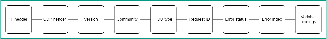
SNMP Protocol Data Unit diagram
To display the table of traps, go to the Infrastructure menu section, click Management → Configuration menu next to the controller to which the components that you want to monitor are connected, and go to the SNMP section. Information about traps is displayed in the following columns of the table:
- # is the serial number of the trap.
- Manager IP is the IP address or host name of the SNMP manager.
- Manager port is the port number of the SNMP manager.
- Community is the SNMP community string.
- Allowed traps are traps that SNMP agents must send to the SNMP manager.
- Description is a brief description of the trap.
Configuring the connection of the SNMP manager to SNMP agents
You must specify the settings for connecting the SNMP manager to SNMP agents installed on CPE devices, as well as on the virtual and physical network functions. The specified settings are used for all SNMP agents.
To configure the connection of the SNMP manager to SNMP agents:
- In the menu, go to the Infrastructure section.
This opens the resource management page. By default, the Network resources tab is selected, which displays the table of SD-WAN Controllers.
- Click Management → Configuration menu next to the controller to which the components that you want to monitor are connected.
This opens the controller configuration menu. By default, you are taken to the Controller nodes section, which displays a table of controller nodes.
- Go to the SNMP section.
A table of traps is displayed.
- In the upper part of the page, under Manager parameters, click Edit.
- This opens a window; in that window, in the Address field, enter the IP address or host name of the equipment on which the SNMP agent is installed, in the
<transport protocol>:<IP address or host name>/<port number>format. For example, you can enterudp:192.168.2.0/24. - In the Community field, enter the SNMP community string. The SNMP community string is used as a password which the SNMP manager uses to connect to SNMP agents. Default value:
publicmeans read-only access is granted. We recommend changing the default to a unique community string to ensure the security of communication between the SNMP manager and the SNMP agents.You must specify the same community string when configuring the SNMP manager connection to SNMP agents and when creating or editing traps.
- Click Save.
The connecting of the SNMP manager to agents is configured.
Page top
Creating a trap
You can create a trap that SNMP agents must send to the SNMP manager.
To create a trap:
- In the menu, go to the Infrastructure section.
This opens the resource management page. By default, the Network resources tab is selected, which displays the table of SD-WAN Controllers.
- Click Management → Configuration menu next to the controller to which the components that you want to monitor are connected.
This opens the controller configuration menu. By default, you are taken to the Controller nodes section, which displays a table of controller nodes.
- Go to the SNMP section.
A table of traps is displayed.
- Under Trap parameters, click Edit.
- This opens a window; in that window, click + Add to create a trap.
- In the Manager IP field, enter the IP address or host name of the SNMP manager. Range of values: 1 to 255.
- In the Manager port field, enter the port number of the SNMP manager. Range of values: 1 to 65,534. Default value:
162. - In the Community field, enter the SNMP community string. The SNMP community string is used as a password which the SNMP manager uses to connect to SNMP agents. Default value:
publicmeans read-only access is granted. We recommend changing the default to a unique community string to ensure the security of communication between the SNMP manager and the SNMP agents.You must specify the same SNMP community string when configuring the SNMP manager connection to SNMP agents and when creating or editing traps.
- In the Allowed traps field, click Edit and clear the following check boxes to specify which traps SNMP agents do not send to the SNMP manager:
- Clear the Trap, when an interface is active check box to prevent the SNMP agent from sending a trap to the SNMP manager when one of the ports of the component on which the SNMP agent is installed becomes active.
- Clear the Trap, when an interface is inactive check box to prevent the SNMP agent from sending a trap to the SNMP manager when one of the ports of the component on which the SNMP agent is installed becomes inactive.
- Clear the Trap, when an equipment is active check box to prevent the SNMP agent from sending a trap to the SNMP manager when the component on which the SNMP agent is installed becomes active.
- Clear the Trap, when an equipment is inactive check box to prevent the SNMP agent from sending a trap to the SNMP manager when the component on which the SNMP agent is installed becomes inactive.
By default, the check boxes are selected.
- Click Back to continue specifying trap settings.
- In the Description field, enter a brief description of the trap.
- Click Save.
The trap is created and displayed in the table.
Page top
Editing a trap
To edit a trap:
- In the menu, go to the Infrastructure section.
This opens the resource management page. By default, the Network resources tab is selected, which displays the table of controllers.
- Click Management → Configuration menu next to the controller to which the components that you want to monitor are connected.
This opens the controller configuration menu. By default, you are taken to the Controller nodes section, which displays a table of controller nodes.
- Go to the SNMP section.
A table of traps is displayed.
- Under Trap parameters, click Edit.
- This opens a window; in that window, if necessary, edit the trap settings. For a description of the settings, see instructions for creating a trap.
- Click Save.
The trap is modified and updated in the table.
Page top
Deleting a trap
Deleted traps cannot be restored.
To delete a trap:
- In the menu, go to the Infrastructure section.
This opens the resource management page. By default, the Network resources tab is selected, which displays the table of controllers.
- Click Management → Configuration menu next to the controller to which the components that you want to monitor are connected.
This opens the controller configuration menu. By default, you are taken to the Controller nodes section, which displays a table of controller nodes.
- Go to the SNMP section.
A table of traps is displayed.
- Under Trap parameters, click Edit.
- This opens a window; in that window, click Delete next to the trap that you want to delete.
- Click Save.
The trap is deleted and is no longer displayed in the table.
Page top
Link monitoring
To enable link monitoring:
- Enable link monitoring in one of the following ways:
- If you want to enable monitoring for a link that was established from a CPE device, go to the SD-WAN → CPE section, click the CPE device, select the Links tab, and click Management → Set thresholds next to the link.
- If you want to enable monitoring of one of the links in the table of all links, go to the Infrastructure section, click Management → Configuration menu next to the controller, go to the Links section, and click Management → Set thresholds next to the link.
- If you want to enable monitoring of one of the links in the graphic topology with all links, go to the Infrastructure section, click Management → Configuration menu next to the controller, go to the Topology section, click the link, and click Set thresholds.
- Select the Enable tunnel thresholds monitoring check box to enable link monitoring. This check box is cleared by default.
- If you want to specify link monitoring thresholds:
- To set default link monitoring thresholds, click Set to default.
- If you want the controller to use the link as the last resort when calculating paths, regardless of monitoring thresholds, select the Unsolicited check box. This check box is cleared by default.
- In the Interval for processing errors and utilization rate (sec.) field, enter the time interval in seconds for measuring the number of errors on the link and its level of utilization. Range of values: 1 to 300. Default value:
60. - If you want to specify a threshold for the number of errors per second on the link, select the Enable error monitoring check box and in the Critical error level (errors/sec.) field, enter the threshold value. Range of values: 1 to 1,000,000. By default, the check box is cleared and the field is set to
1000. - If you want to specify a threshold for link utilization as a percentage of the bit rate of the source service interface, select the Enable utilization monitoring check box and in the Critical utilization level (%) field, enter the threshold value. By default, the check box is cleared and the field is set to
95. - In the Interval for processing latency, jitter, and packet loss (sec.) field, enter the time interval, in seconds, for measuring latency, jitter, and packet loss on the link. Range of values: 1 to 600. Default value:
30. - If you want to specify a threshold for latency in milliseconds for transmitting traffic over the link, select the Enable latency monitoring check box and in the Critical latency level (ms.) field, enter the threshold value. Range of values: 5 to 1000. By default, the check box is cleared and the field is set to
100. - If you want to specify a threshold for jitter time in milliseconds for transmitting traffic over the link, select the Enable jitter monitoring check box and in the Critical jitter level (ms.) field, enter the threshold value. Range of values: 5 to 1000. By default, the check box is cleared and the field is set to
100. - If you want to specify a threshold for the percentage of lost traffic packages on the link, select the Enable packet loss monitoring check box and in the Critical packet loss level (%) field, enter the threshold value. Range of values: 1 to 100. By default, the check box is cleared and the field is set to
2.
The specified monitoring thresholds are used by the threshold constraints.
- Save the link monitoring settings in one of the following ways:
- To save the link monitoring settings, click Save.
- If you want to save the link monitoring settings and specify the same settings on the opposite-direction link, click Save for both tunnels.
If you have specified link monitoring settings for a link established from the CPE device, click Save in the upper part of the settings area to save the CPE device settings.
Building an SD-WAN network between CPE devices
To transfer traffic, you need to build an SD-WAN network between CPE devices using links that are established on top of the underlay network. CPE devices establish links from all available SD-WAN interfaces of the WAN type. The links are unidirectional. This means that when establishing a link from CPE 1 to CPE 2, a link is automatically established also from CPE 2 to CPE 1. Before building an SD-WAN network, you must ensure connectivity between CPE devices.
Links are established based on the roles that you assign to CPE devices. You can assign the SD-WAN Gateway role or the standard CPE device role to a CPE device. SD-WAN Gateways establish links with all standard CPE devices and other SD-WAN Gateways. Standard CPE devices establish links only with SD-WAN Gateways. By default, all CPE devices have the standard CPE device role.
If you want a link to be established between two standard CPE devices, you need to assign the same topology tag to these standard CPE devices. You can also make a standard CPE device a transit device to allow other CPE devices to establish links through that CPE device.
The links between CPE devices form a topology. The following topologies are the most commonly used in Kaspersky SD-WAN:
- In a Hub-and-Spoke topology, links between CPE devices are established through SD-WAN gateways.
- In Full-Mesh and Partial-Mesh topologies, links between CPE devices are established directly, or some links are established directly, while others are established through SD-WAN gateways.
Within the SD-WAN network, traffic between CPE devices can take multiple paths. The paths go through the links between CPE devices. The totality of all possible paths between two CPE devices is called a segment. The segment source CPE device can distribute the traffic bound to the segment destination CPE device across multiple paths. One segment can contain 2 to 16 paths.
The following path types are supported:
- Auto-SPF (Shortest-Path Forwarding) is a path that is automatically calculated by the controller. You can forward traffic along Auto-SPF paths in two modes:
- In Active/Active mode, multiple Auto-SPF paths are used simultaneously to forward traffic between CPE devices.
- In Active/Standby mode, one Auto-SPF path with the lowest cost is used to forward traffic between CPE devices. If the Auto-SPF path being used becomes unavailable, the Auto-SPF path with the next lowest cost is used. The path cost is calculated by adding up the cost of every link traversed by the path. You can manually specify link cost.
You can configure the traffic forwarding mode along Auto-SPF paths when configuring the paths.
- Auto-TE (Traffic Engineering) is a path automatically calculated by the controller, taking into account the threshold constraints you specified.
- Manual-TE is a path that you manually created. When creating a Manual-TE path, specify the links that the path passes through on the way from the segment source CPE device to the segment destination CPE device.
About the Hub-and-Spoke topology
In a Hub-and-Spoke topology, the hub site is connected to multiple spoke sites to exchange traffic. This topology is the most common for SD-WAN network design because it simplifies network management and provides a higher level of security by routing traffic through the hub site where traffic analysis and categorization is performed. The Hub-and-Spoke topology also enables more efficient use of bandwidth by optimizing and prioritizing traffic at the hub site.
To build a Hub-and-Spoke topology, you need to assign the SD-WAN gateway and standard CPE roles to CPE devices. In this case, SD-WAN gateways establish links with other SD-WAN gateways and standard CPE devices, while standard CPE devices establish links only with SD-WAN gateways.
You can use quality of service to limit bandwidth for CPE devices or traffic classes.
Examples of Hub-and-Spoke topologies:
- Hub-and-Spoke topology without connection between spoke sites.
The figure below shows a Hub-and-Spoke topology in which spoke sites communicate with the hub site, but not with each other. SD-WAN networks built using this topology are easy to design and maintain, because all necessary network services and applications are located in the same data center.
CPE devices being registered are automatically included in the management transport service with the Leaf role and can be behind NAT (Network Address Translation) and PAT (Port Address Translation). In such a Hub-and-Spoke topology, traffic cannot be transmitted directly between CPE devices.
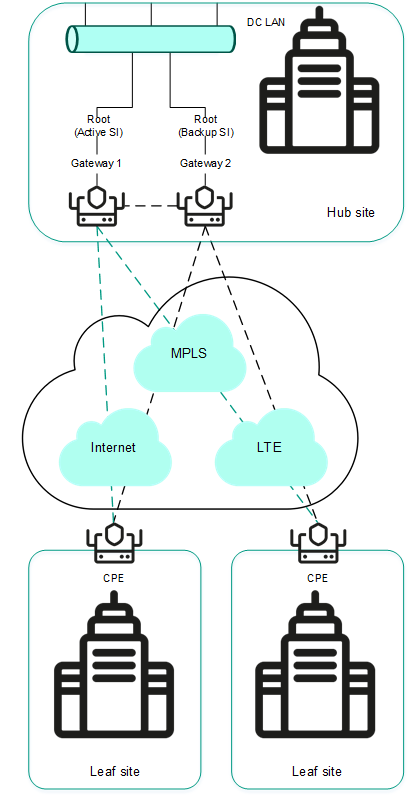
Hub-and-Spoke topology without connection between spoke sites
- Hub-and-Spoke topology with connection between spoke sites through the hub site.
The figure below shows a Hub-and-Spoke topology in which spoke sites can communicate with each other through the hub site. CPE devices being registered are automatically added to the management transport service and may be behind NAT and PAT.

Hub-and-Spoke topology with connection between spoke sites through the hub site
About Full-Mesh and Partial-Mesh topologies
In Full-Mesh and Partial-Mesh topologies, links are established between standard CPE devices. Establishing links between standard CPE devices has the following advantages over a Hub-and-Spoke topology in which standard CPE devices must communicate with each other through SD-WAN gateways:
- Improved aspects of link quality, such as delay, packet loss, and jitter.
- Higher bandwidth of links.
- Economy of hardware resources of SD-WAN gateways.
To build a Full-Mesh topology, you need to assign the standard CPE device role to the CPE devices and assign the same topology tag to the standard CPE devices. In this case, standard CPE devices with the same topology tags establish links with each other.
To build a Partial-Mesh topology, you need to assign the SD-WAN gateway and standard CPE device roles to the CPE devices and assign the same topology tag to the standard CPE devices. In this case, SD-WAN gateways establish links with other SD-WAN gateways and with standard CPE devices, while the standard CPE devices establish links with SD-WAN gateways and with each other provided the same topology tag is assigned to the standard CPE devices. If you want to divide the standard CPE devices into groups, you need to assign a unique topology tag to all standard CPE devices in each group, and also assign a topology tag to be shared by at least one standard CPE device in each group.
You can use quality of service to limit bandwidth for CPE devices or traffic classes.
Full-Mesh and Partial-Mesh topology examples:
- Full-Mesh topology.
The figure below shows a Full-Mesh topology in which all CPE devices establish links with each other. Traffic between CPE 1 and CPE 2 devices is forwarded directly. With a large number of CPE devices and links, this topology can be extremely taxing on the resources of the controller.
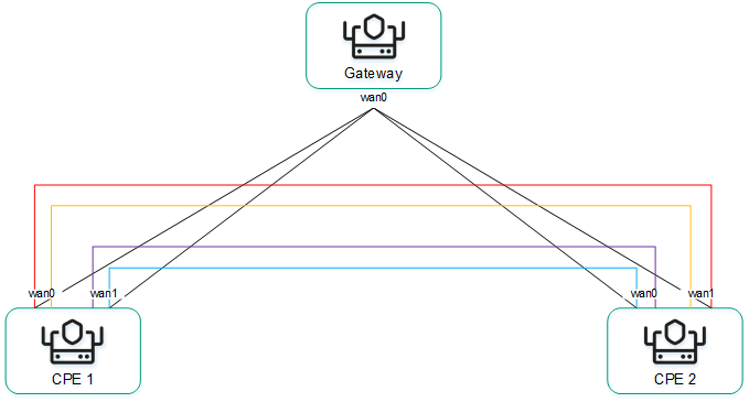
Full-Mesh topology
- Partial-Mesh topology.
The figure below shows a Partial-Mesh topology. This topology is used when direct links between some CPE devices may be undesirable for administrative reasons, or impossible for technical reasons. In this topology, you can group CPE devices in such a way that CPE devices in the same group communicate directly with each other and communicate with CPE devices from other groups through a transit CPE device.
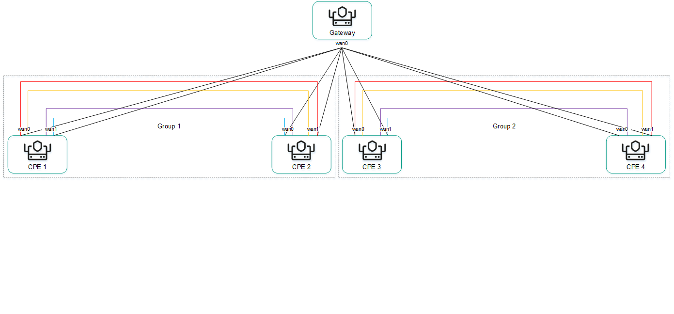
Partial-Mesh topology
A CPE device can belong to multiple groups at the same time, as shown in the figure below.
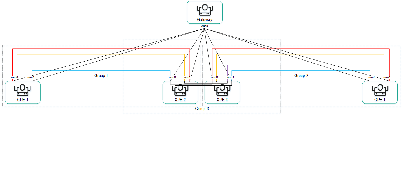
Partial-Mesh topology, CPE devices in multiple groups
When creating direct links between CPE devices, depending on the type of connectivity of the CPE devices through physical links, the following variants of overlay connectivity are possible:
- All physical links have direct IP connectivity to each other.
Thanks to the connectivity within the internet, CPE devices can establish the maximum number of links with each other (see the figure below).
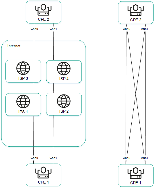
Full physical connectivity between CPE devices
- Physical links have partial IP connectivity to each other.
In the figure below, the internet cloud and the MPLS cloud are not connected to each other, so links can only be established through SD-WAN interfaces of the WAN type that belong to the same cloud. CPE1:WAN0 → CPE2:WAN1 and CPE1:WAN1 → CPE2:WAN0 links cannot be established.
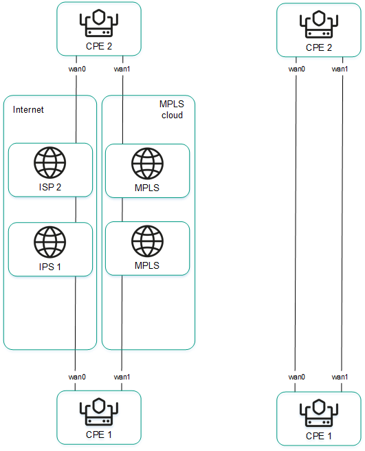
Other overlay network connectivity scenarios are also possible if IP connectivity between SD-WAN interfaces of the WAN type of CPE devices within the same cloud is impossible for other reasons, for example, when using an MPLS topology that does not support direct communication between CPE devices, or due to the presence of NAT/PAT or ACL on the internet.
Assigning a role to a CPE device
You can assign a role to a CPE template or a CPE device. A role assigned to a CPE template is automatically assigned to all CPE devices that use this CPE template.
To assign a role to a CPE device:
- Assign a role to a CPE device in one of the following ways:
- If you want to assign a role to a CPE template, go to the SD-WAN → CPE templates menu section, click the CPE template, and select the Topology tab.
- If you want to assign a role to a CPE device, do one of the following:
- In the menu, go to the SD-WAN → CPE section, click the CPE device, select the Topology tab, and select the Override check box.
- In the menu, go to the Infrastructure section, click Management → Configuration menu next to the controller, go to the Topology tags section, and in the Switch drop-down list, select the CPE device.
- In the Role drop-down list, select the role of the CPE device:
- CPE for a standard CPE device. Default value.
- Gateway for an SD-WAN Gateway. You cannot assign topology tags to SD-WAN gateways.
- Save the CPE device role in one of the following ways:
- If you have assigned a role to a CPE template or a CPE device in the SD-WAN section, in the upper part of the settings area, click Save to save the settings of the CPE template or CPE device.
- If you have assigned a role to a CPE device in the Topology tags section, in the upper part of the page, click Save.
The role is assigned to the CPE device.
Page top
Assigning a topology tag to a CPE device
You can assign a topology tag to a CPE template or a CPE device. A topology tag assigned to a CPE template is automatically assigned to all CPE devices that use this CPE template. CPE devices with the same topology tags automatically establish links with each other. A topology tag cannot be assigned to a CPE device if you have assigned the SD-WAN Gateway role to the CPE device.
To assign a topology tag to a CPE device:
- Assign a topology tag to a CPE device in one of the following ways:
- If you want to assign a topology tag to a CPE template, go to the SD-WAN → CPE templates menu section, click the CPE template, and select the Topology tab.
- If you want to assign a topology tag to a CPE device, do one of the following:
- In the menu, go to the SD-WAN → CPE section, click the CPE device, select the Topology tab, and select the Override check box.
- In the menu, go to the Infrastructure section, click Management → Configuration menu next to the controller, go to the Topology tags section, and in the Switch drop-down list, select the CPE device.
Topology tags are displayed.
- In the Topology tags field, enter the topology tag that you want to assign to the CPE device and click the add icon .
The topology tag is assigned to the CPE device. You can assign multiple topology tags or remove a topology tag. To remove a topology tag, click the remove icon
next to it. - Save the topology tags of the CPE device in one of the following ways:
- If you have assigned a topology tag to a CPE template or a CPE device in the SD-WAN section, in the upper part of the settings area, click Save to save the settings of the CPE template or CPE device.
- If you have assigned a topology tag to a CPE device in the Topology tags section, in the upper part of the page, click Save.
Configuring paths
You can configure paths in a segment, CPE template or on the CPE device. Path settings specified in a segment or a CPE template are automatically propagated to all CPE devices that belong to this segment or use this CPE template. Path settings specified on a CPE device are automatically propagated to all CPE devices that belong to the same segment as that CPE device.
To configure paths:
- Configure paths in one of the following ways:
- If you want to configure paths in a segment, go to the Infrastructure section, click Management →Configuration menu next to the controller, go to the Segments section, and click Management → Edit next to the segment.
- If you want to configure paths in a CPE template, go to the SD-WAN → CPE templates menu section, click the CPE template, and select the Multipathing tab.
- If you want to configure paths on a CPE device, go to the SD-WAN → CPE menu section, click the CPE device, and select the Multipathing tab.
Path settings are displayed.
- In the Maximum number of paths field, enter the maximum number of paths supported by the CPE device or segment. Range of values: 1 to 16. Default value:
8. - In the Maximum of Auto-SPF field, enter the maximum number of Auto-SPF paths supported by the CPE device or segment. Auto SPF paths are automatically calculated by the controller. Range of values: 1 to 8. Default value:
2.If you want traffic to be transmitted between CPE devices in Active/Active mode, enter a value greater than
1in this field. If you want traffic to be transmitted between CPE devices in Active/Standby mode, enter1in this field. - In the Cost variance multiplier field, enter the maximum ratio of the cost of this path to the lowest cost of any path on your SD-WAN network; if the cost of the path is below this limit, the path can be added to the segment. Range of values: 1.0 to 10.0. Default value:
10. You cannot enter a value in this field if the Multi-weight balancing check box is selected.For example, if you enter
2in this field, and the lowest path cost in your SD-WAN network is 10,000, paths with a cost of up to 20,000 can be added to the segment. In Active /Standby mode, the value in this field determines which Auto-SPF path is used if the previous Auto-SPF path becomes unavailable. - If you want paths to be added to the segment regardless of their cost, select the Multi-weight balancing check box. This check box is cleared by default.
- Save the path settings in one of the following ways:
- If you have configured paths in the segment, click Save to save the segment settings.
- If you have configured paths in a CPE template or on a CPE device, in the upper part of the settings area, click Save to save the settings of the CPE template or CPE device.
Path settings are saved.
Page top
Managing links
You can view the links in one of the following ways:
- To display the table of links established from a CPE device, go to the SD-WAN → CPE menu section, click the CPE device, and select the Links tab.
- To display the table of all links, go to the Infrastructure menu section, click Management → Configuration menu next to the controller, and go to the Links section.
- To display the graphical topology with all links, go to the Infrastructure menu section, click Management → Configuration menu next to the controller, and go to the Topology section.
When viewing the table of links, information about the links is displayed in the following table columns:
- Source is the name, DPID, and OpenFlow port number of the CPE device that is the link source.
- Destination is the name, DPID, and OpenFlow port number of the CPE device that is the link destination.
- Unsolicited indicates whether the controller uses this link as the last resort when calculating the path, regardless of the monitoring indicators:
- Y
- N
- Thresholds monitoring indicates whether link monitoring is on:
- Y
- N
- MTU is the MTU value of the link.
- Errors/second is the number of errors per second on the link.
- Utilization (%) is the load of the link as a percentage of the bandwidth of the source service interface.
- Latency (ms.) is the delay time in milliseconds for traffic transmitted through the link.
- Jitter (ms.) is the jitter time in milliseconds for traffic transmitted through the link.
- Packet loss (%) is the percentage of traffic packet loss on the link.
- Speed (Mbit/sec.) is the speed of traffic transmission through the link in Mbps.
- Cost is the link cost.
The actions you can perform with the table are described in the Managing solution component tables instructions.
Specifying the cost of a link
To specify the cost of a link:
- Specify the link cost in one of the following ways:
- If you want to specify the cost of a link that was established from a CPE device, go to the SD-WAN → CPE section, click the CPE device, select the Links tab, and click Management → Set cost next to the link.
- If you want to specify the cost of one of the links in the table of all links, go to the Infrastructure section, click Management → Configuration menu next to the controller, go to the Links section, and click Management → Set cost next to the link.
- If you want to specify the cost of one of the links in the graphic topology with all links, go to the Infrastructure section, click Management → Configuration menu next to the controller, go to the Topology section, click the link, and click Set cost.
- This opens a window; in that window, select the Override check box to specify the cost of the link. This check box is cleared by default.
- In the Tunnel cost field, enter the cost of the link. If you want to specify the same cost for the opposite-direction link, select the Save for both tunnels check box. This check box is cleared by default.
- Click Save.
The link cost is specified.
- If you have specified the link cost for a link established from the CPE device, click Save in the upper part of the settings area to save the CPE device settings.
Enabling Dampening
Dampening is a configurable mechanism that excludes unstable links whose state changes too frequently from path calculation. When determining link instability, the following state changes are taken into account:
- UP/LIVE → DOWN/NOT-LIVE.
- DOWN/NOT-LIVE → UP/LIVE.
- UP/LIVE → UP/NOT-LIVE.
- UP/NOT-LIVE → UP/LIVE.
When Dampening is enabled, each state change of the link increases the Penalty value. If the Penalty reaches the threshold within the specified time, access to the link is restricted (its cost is increased 10,000 times for the specified period of time). The value of each of these parameters is specified when you enable Dampening. By default, access to the link is resumed if the state of the link does not change for 10 minutes.
To enable Dampening:
- Enable Dampening in one of the following ways:
- If you want to enable Dampening for a link that was established from a CPE device, go to the SD-WAN → CPE section, click the CPE device, select the Links tab, and click Management → Dampening next to the link.
- If you want to enable Dampening for one of the links in the table of all links, go to the Infrastructure section, click Management → Configuration menu next to the controller, go to the Links section, and click Management → Dampening next to the link.
- If you want to enable Dampening for one of the links in the graphic topology with all links, go to the Infrastructure section, click Management → Configuration menu next to the controller, go to the Topology section, click the link, and click Dampening.
- This opens a window; in that window, select the Enable check box to enable Dampening on the link. This check box is cleared by default.
- In the Maximum suppress time (ms.) field, enter the time, in milliseconds, for which access to the link can be restricted. When the specified time elapses, all Dampening counters on the link are reset. Default value:
600000. - In the Penalty field, enter the number by which Penalty is incremented when the link changes state. Default value:
1. - In the Suppress threshold field, enter the Penalty value at which access to the link is restricted. Default value:
4. - In the Update interval (ms.) field, enter the time in milliseconds during which Penalty must attain the value specified in the Suppress threshold field for access to the link to be restricted. Default value:
120000. - If you want to view Dampening statistics for a link, click Load statistics.
- Click Save.
Dampening is enabled for the link.
- If you enabled Dampening for a link established from the CPE device, click Save in the upper part of the settings area to save the CPE device settings.
Enabling Forward Error Correction
The Forward Error Correction (FEC) functionality reduces the loss of traffic packets in links, especially for UDP applications, and the number of retransmissions, which lead to delays, and also recovers received data on the CPE device. Data recovery is provided by redundant encoding of the data stream on the device on the source CPE device.
The source CPE device encodes the traffic packet stream transmitted through the link and adds redundant traffic packets. Encoding on CPE devices may cause delays due to extra data processing.
The destination CPE device buffers traffic packets received through the link and decodes them, recovering lost traffic packets, if possible. We recommend using FEC on noisy links to reduce the packet loss and increase the speed of TCP connections. The general diagram of FEC is shown in the figure below.
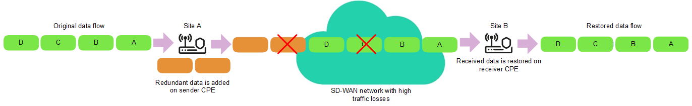
FEC diagram
To enable FEC:
- Enable FEC in one of the following ways:
- If you want to enable FEC for a link that was established from a CPE device, go to the SD-WAN → CPE section, click the CPE device, select the Links tab, and click Management → FEC/reordering next to the link.
- If you want to enable FEC for one of the links in the table of all links, go to the Infrastructure section, click Management → Configuration menu next to the controller, go to the Links section, and click Management → FEC/reordering next to the link.
- If you want to enable FEC for one of the links in the graphic topology with all links, go to the Infrastructure section, click Management → Configuration menu next to the controller, go to the Topology section, click the link, and click FEC/reordering.
- This opens a window; in that window, select the Override check box to enable FEC on the link. This check box is cleared by default.
- In the Redundancy ratio (original/redundant packet) drop-down list, select the ratio of original traffic packets to extra traffic packets with redundant code. Default value: 0:0 FEC off means FEC is not used. You can also specify the ratio of original traffic packets to redundant traffic packets by using the
topology.link.fec.ratiocontroller property. - In the Timeout field, enter the time, in milliseconds, during which a traffic packet can stay in the queue for FEC to apply. Range of values: 1 to 1000.
- Click Save.
FEC is enabled.
- If you enabled FEC for a link established from the CPE device, click Save in the upper part of the settings area to save the CPE device settings.
Determining the MTU value
You can determine the MTU value of a link to find out why fragmented packets are being blocked on the link (see the figure below).
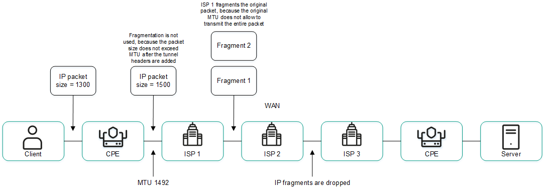
Links with a reduced MTU size and fragmented packet getting dropped
The MTU value is determined by sending LLDP packets with a variable payload size through the link. The minimum detectable MTU size is 1280 bytes, and the maximum is 1500 bytes. The MTU value is determined automatically when CPE devices are enabled and periodically at an interval specified in the topology.link.pmtud.scheduler.interval.sec controller property.
You can determine the MTU value manually.
To manually determine the MTU value,
Determine the MTU value in one of the following ways:
- If you want to manually determine the MTU value for a link that was established from a CPE device, go to the SD-WAN → CPE section, click the CPE device, select the Links tab, and click Management → Check MTU next to the link.
- If you want to manually determine the MTU value for one of the links in the table of all links, go to the Infrastructure section, click Management → Configuration menu next to the controller, go to the Links section, and click Management → Check MTU next to the link.
The MTU value is displayed in the MTU column.
Page top
Traffic encryption
Traffic encryption is a mechanism of securing the exchange of traffic between CPE devices through links. For example, you can encrypt traffic that is transmitted over unsecured connections.
Traffic encryption does not replace the need to use other information security measures, such as TLS, LDAPS, and other protocols that protect traffic within the overlay network.
The controller automatically generates keys for encrypting and decrypting traffic and sends the keys to CPE devices. Traffic is encrypted on the source CPE device using the encryption key. The destination CPE device decrypts the traffic using the decryption key.
The keys are regularly updated to deprive third parties of the opportunity to encrypt or decrypt the transmitted traffic if a key is intercepted. You can specify the length of time after which the keys are updated on CPE devices using the topology.link.encryption.key.update.interval.minutes controller property.
Traffic encryption is supported only on CPE devices running Kaspersky SD-WAN software.
If traffic encryption is enabled on a CPE device, all outbound links that involve this CPE device send encrypted traffic (including new links that will be established later). If traffic encryption is disabled on a CPE device, it sends unencrypted traffic. If you disable traffic encryption on a CPE device that had been encrypting its outgoing traffic, the keys generated by the SD-WAN Controller for encrypting and decrypting traffic are deleted from all related CPE devices.
You can also enable or disable traffic encryption on links. For example, you can enable traffic encryption on a CPE device, but disable it on a link built with the participation of this CPE device. When enabling or disabling traffic encryption on a link, you need to configure the opposite-direction link in the same way.
Enabling traffic encryption on a CPE device
You can enable or disable traffic encryption in a CPE template or on a CPE device. Traffic encryption settings specified in the CPE template are automatically propagated to all CPE devices that use this CPE template.
To enable traffic encryption on a CPE device:
- Enable traffic encryption on the CPE device in one of the following ways:
- If you want to enable traffic encryption in a CPE template, go to the SD-WAN → CPE templates menu section, click the CPE template, and select the Tunnel encryption tab.
- If you want to enable traffic encryption on a CPE device, go to the SD-WAN → CPE menu section, click the CPE device, select the Tunnel encryption tab, and select the Override check box.
The traffic encryption policy is displayed.
- In the Default encryption policy drop-down list, select one of the following values:
- Enabled
- Disabled Default value.
- In the upper part of the settings area, click Save to save the settings of the CPE template or CPE device.
Enabling traffic encryption on a link
When enabling or disabling traffic encryption on a link, you must configure the opposite-direction link in the same way.
To enable encryption of traffic on a link:
- Enable traffic encryption on the link in one of the following ways:
- If you want to enable traffic encryption for a link that was established from a CPE device, go to the SD-WAN → CPE section, click the CPE device, select the Links tab, and click Management → Set encryption next to the link.
- If you want to enable traffic encryption for one of the links in the table of all links, go to the Infrastructure section, click Management → Configuration menu next to the controller, go to the Links section, and click Management → Set encryption next to the link.
- If you want to enable traffic encryption for one of the links in the graphic topology with all links, go to the Infrastructure section, click Management → Configuration menu next to the controller, go to the Topology section, click the link, and click Set encryption.
- This opens a window, in that window, select the Override check box. This check box is cleared by default.
- Select the Enable encryption check box to enable traffic encryption for the link. This check box is cleared by default.
- Click Save.
Traffic encryption is enabled on the link.
- If you enabled traffic encryption for a link established from the CPE device, click Save in the upper part of the settings area to save the CPE device settings.
Managing segments
To display the table of segments, go to the Infrastructure menu section, click Management → Configuration menu next to the controller, and go to the Segments section. Information about segments is displayed in the following columns of the table:
- From is the name and DPID of the CPE device of the segment source.
- To is the name and DPID of the CPE device of the segment destination.
- Paths/maximum is the number of paths created and the maximum number of paths supported by the segment.
- # is the sequential number of the path. The lower the path number, the earlier the path was built.
- Path type is the type of the path:
- Auto SPF
- Auto TE
- Manual TE
- Transport paths are names, DPIDs, and numbers of OpenFlow ports of CPE devices through which the path passes.
- Administrative state is the administrative state of the path:
- up
- down
- Operational state is the operational state of the path:
- up
- down
- Cost is the the cost of the path.
- Hop count is the number of hops in the path.
The actions that you can perform with the table are described in the Managing solution component tables instructions.
When creating or editing a Manual-TE path in a segment, you can view the table of hops added to the Manual-TE path. Information about hops is displayed in the following columns of the table:
- # is the sequential number of the hop. The lower the number of the hop, the earlier the hop was added.
- From is the name, DPID, and OpenFlow port number of the CPE device that is the hop source.
- To is the name, DPID, and OpenFlow port number of the CPE device that is the hop destination.
- Cost is the the cost of the hop.
The total cost of the Manual-TE path is displayed in the lower part of the table.
Page top
Creating a Manual-TE path
When creating a Manual-TE path, you must manually specify the links that the path passes through on the way from the segment source CPE device to the segment destination CPE device. Two types of Manual-TE paths are supported:
- A fully defined Manual-TE path specifies each CPE device and service interface through which the Manual-TE path passes.
- A hybrid Manual-TE path specifies one or more CPE devices and service interfaces through which the Manual-TE path passes. In this case, traffic between sections of the Manual-TE path that are not manually specified is transmitted automatically (an Auto-SPF path is used).
You can use Manual-TE constraints to add Manual-TE paths to transport services.
Examples of possible Manual-TE paths: In the examples, an OpenFlow port number is specified after the CPE device number, separated by a colon. Fully defined Manual-TE path: CPE 1:3 → CPE 2:1, CPE 2:2 → CPE 4:1, CPE 4:5 → CPE N:2. Hybrid Manual-TE path: CPE 1 → CPE 5, CPE 5:3 → CPE 4:3, CPE 4 → CPE N. In this case, the path from CPE 1 to CPE N is built as an Auto-SPF path CPE 1 → CPE 5, a Manual-TE path CPE 5:3 → CPE 4:3, and an Auto-SPF path CPE 4 → CPE N. |
To create a Manual-TE path:
- In the menu, go to the Infrastructure section.
This opens the resource management page. By default, the Network resources tab is selected, which displays the table of controllers.
- Click Management → Configuration menu next to the controller.
This opens the controller configuration menu. By default, you are taken to the Controller nodes section, which displays a table of controller nodes.
- Go to the Segments section.
A table of segments is displayed.
- Click Management → Edit next to the segment in which you want to create a Manual-TE path.
The settings and the path table are displayed.
- Click + Manual-TE path.
The Manual-TE path settings and the hop table are displayed.
- In the Name field, enter the name of the Manual-TE path.
- In the Maximum number of hops field, enter the maximum number of hops in the Manual-TE path. Range of values: 1 to 8. Default value:
4. - Add the hop to the Manual-TE path:
- In the From drop-down list on the left, select the source CPE device for the hop.
If you are adding the first hop to the Manual-TE path, you can select only the CPE device of the segment source as the source CPE device of the hop. If you have added at least one hop to the Manual-TE path, you can only select the destination CPE device of the previous hop as the source CPE device of the current hop.
- If necessary, in the Port drop-down list on the left, select the OpenFlow port of the hop source. Default value: Automatically means the OpenFlow port is determined automatically.
- In the To drop-down list on the right, select the CPE device at the end of the hop.
If in the Port drop-down list you selected Automatically as the hop source CPE device, you can select any CPE device that is not being used in other hops as the hop destination. In this case, in the Port drop-down list, Automatically is selected for the hop destination CPE device, and the OpenFlow port is detected automatically. Thus, the hop uses an Auto-SPF path.
If in the Port drop-down list, you selected an OpenFlow port for the hop source CPE device, for the hop destination CPE device, you can only use a CPE device that has a link built from that OpenFlow port. In this case, in the Port drop-down list, the OpenFlow port to which the link is built is automatically selected as the hop destination CPE device. Thus, the hop uses the link specified between the two CPE devices.
- If necessary, in the Port drop-down list on the right, select the OpenFlow port of the hop destination CPE device. Default value: Automatically means the OpenFlow port is determined automatically.
- Click Add.
The hop is created and displayed in the table. You can add multiple hops or delete a hop. To delete a hop click Delete next to it.
- In the From drop-down list on the left, select the source CPE device for the hop.
- Click Create.
A check is performed to make sure the destination CPE device of the last hop matches the destination CPE device of the segment in which you are creating the Manual-TE path. If the check is successful, the Manual-TE path is created and displayed in the table, and the column Cost displays the cost of the Manual-TE path, which is the sum total of the cost of all hops that you added to this Manual-TE path.
- Click Save to save the settings of the segment.
Editing a Manual-TE path
To edit a Manual-TE path:
- In the menu, go to the Infrastructure section.
This opens the resource management page. By default, the Network resources tab is selected, which displays the table of controllers.
- Click Management → Configuration menu next to the controller.
- Go to the Segments section.
A table of segments is displayed.
- Click Management → Edit next to the segment in which you want to edit a Manual-TE path.
The settings and the path table are displayed.
- Click Edit next to the Manual-TE path that you want to edit.
- If necessary, edit the Manual-TE path settings. For a description of the settings, see the instructions for creating a Manual-TE path.
- Click Save.
The Manual-TE path is modified and updated in the table.
- Click Save to save the settings of the segment.
Deleting a Manual-TE path
Deleted Manual-TE paths cannot be restored.
To delete a Manual-TE path:
- In the menu, go to the Infrastructure section.
This opens the resource management page. By default, the Network resources tab is selected, which displays the table of controllers.
- Click Management → Configuration menu next to the controller.
- Go to the Segments section.
A table of segments is displayed.
- Click Management → Edit next to the segment in which you want to delete a Manual-TE path.
The settings and the path table are displayed.
- Click Delete next to the Manual-TE path that you want to delete.
- Click Save to save the settings of the segment.
Quality of Service (QoS)
A Quality of Service (QoS) policy ensures data transfer in accordance with the requirements set for traffic classes. In Kaspersky SD-WAN, the following components contribute to the quality of service:
- Traffic classes - indicate the priority of traffic processing and distribute traffic among queues. For example, you can use one of the traffic classes for real-time traffic that requires minimizing packet loss. You can map traffic to traffic classes when creating or editing a traffic classifier.
- Traffic classifiers determine whether or not the DSCP values specified in the traffic packet header fields must be trusted. If a traffic classifier does not trust DSCP values, it maps them to traffic classes. You can specify a traffic classifier when creating or editing a quality of service rule to make the quality of service rule use this traffic classifier.
- Quality of service rules determine whether the bandwidth of traffic processed by traffic classifiers is limited. You can specify a quality of service rule when you create or edit a transport service to make the transport service use this quality of service rule.
- Constraints are used to configure how the paths are built in transport services. You can create two types of constraints:
- Manual-TE constraints add Manual-TE paths to transport services.
- Threshold constraints specify link monitoring thresholds that are used to build Auto-TE paths in transport services.
You can specify a constraint when creating or editing a transport service to make the transport service use this constraint.
- Traffic classification rules identify traffic with particular values of the L2 – L4 header fields, as well as traffic of specified applications, in the overall stream of traffic. You can specify a traffic classification rule when creating or editing a traffic filter to make the traffic filter use this traffic classification rule.
- Traffic filters filter traffic based on specified traffic classification rules. You can specify a traffic filter when creating or editing a transport service or ACL interface to make the transport service or ACL interface use this traffic filter.
Managing traffic classes
About traffic classes
The table of traffic classes is displayed in the SD-WAN instance template and in the controller configuration menu:
- To display the table of traffic classes in an SD-WAN instance template, go to the SD-WAN → SD-WAN instance templates section, click the SD-WAN instance template, and select the Traffic classes tab.
- To display the table of traffic classes in the controller settings menu, go to the Infrastructure menu section, click Management → Configuration menu next to the controller, and go to the Traffic classes section.
By default, the following traffic classes are created:
- Best effort
- Business normal
- Business critical
- Video
- Conference
- Signaling
- Real time
- Network control
Information about traffic classes is displayed in the following columns of the table:
- Name is the name of the traffic class.
- Internal tag is the internal tag of the traffic class.
- Queue is the number of the queue to which traffic from the traffic class goes.
- KOver is the overcommitment ratio of the traffic bandwidth, which sets the multiplier by which the bandwidth dedicated to the traffic class can be increased if the total bandwidth is not fully utilized.
- Exclude when computing path indicates whether the bandwidth available to the traffic class is taken into account when calculating the route:
- Yes
- No
The following parameters are displayed in the lower part of the table:
- Default traffic class is the traffic class in which all traffic is placed that is not included in other classes.
- Control traffic class is the traffic class in which control traffic is placed that is used to manage solution components. We recommend assigning the highest priority to control traffic to make sure the network works reliably.
- Maximum reserved bandwidth (%) is the percentage of the maximum traffic transfer rate that can be available for the traffic class.
Kaspersky SD-WAN does not support creating traffic classes, but you can edit the default traffic classes in the SD-WAN instance template or in the controller configuration menu.
Editing a traffic class
You can edit a traffic class in an SD-WAN instance template or in the controller configuration menu. If you edit a traffic class in an SD-WAN instance template, that traffic class is not modified in the controller configuration menu of already deployed SD-WAN instances.
Default traffic classes are suitable for most deployment scenarios, and we do not recommend editing them.
To edit a traffic class:
- Edit a traffic class in one of the following ways:
- If you want to edit the traffic class in an SD-WAN instance template, go to the SD-WAN → SD-WAN instance templates section, click the SD-WAN instance template, and select the Traffic classes tab.
- If you want to edit the traffic class in the controller settings menu, go to the Infrastructure section, click Management → Configuration menu next to the controller, and go to the Traffic classes section.
A table of traffic classes is displayed.
- Click Edit.
- In the Name column, enter the name of the traffic class.
- In the Queue column, select the number of the queue into traffic of the selected class goes. The higher the value, the higher the priority of the traffic class. You cannot specify the same priority for multiple traffic classes.
- In the KOver column, select the overcommitment ratio of the traffic bandwidth, which sets the multiplier by which the bandwidth dedicated to the traffic class can be increased if the total bandwidth is not fully utilized.
- If you want to ignore the bandwidth available to the traffic class when building the route, select the Exclude when computing path check box. When this check box is selected, you cannot select the KOver ratio for the traffic class. By default, the check box is selected next to the Best effort traffic class.
- In the Default traffic class drop-down list, select the traffic class in which all traffic is placed that is not included in other classes. By default, the Best effort traffic class is selected.
- In the Control traffic class drop-down list, select the traffic class in which you want control traffic is placed. By default, the Network control traffic class is selected.
- In the Maximum reserved bandwidth (%) drop-down list, select the percentage of the maximum traffic transfer rate that can be available for the traffic class. Range of values: 10 to 90. Default value: 90.
- Click Ok. If you have modified a traffic class in the SD-WAN instance template, in the upper part of the settings area, click Save to save the SD-WAN instance template settings.
The traffic class is modified.
Page top
Managing traffic classifiers
The table of traffic classifiers is displayed in the SD-WAN instance template and in the controller configuration menu:
- To display the table of traffic classifiers in an SD-WAN instance template, go to the SD-WAN → SD-WAN instance templates section, click the SD-WAN instance template, and select the Traffic classifiers tab.
- To display the table of traffic classifiers in the controller settings menu, go to the Infrastructure menu section, click Management → Configuration menu next to the controller, and go to the Traffic classifiers section.
By default, the Untrust-BE-Classifier is created, which does not trust DSCP values in traffic packet header fields and puts all traffic in the Best effort traffic class. Information about traffic classes is displayed in the following columns of the table:
- Name is the name of the traffic classifier.
- Type indicates whether the classifier trusts the DSCP values set in the header fields of traffic packets:
- Yes
- No
- Traffic class are traffic classes into which the traffic classifier puts traffic.
- Packet field are traffic packet headers.
- External tag is the DSCP value that the traffic packet headers must contain for the traffic classifier to put traffic in the traffic class.
The actions you can perform with the table are described in the Managing solution component tables instructions.
Creating a traffic classifier
You can create a traffic classifier in an SD-WAN instance template or in the controller configuration menu. If you create a traffic classifier in an SD-WAN instance template, that traffic classifier is not created in the controller configuration menu of already deployed SD-WAN instances.
To create a traffic classifier:
- Create a traffic classifier in one of the following ways:
- If you want to create a traffic classifier in an SD-WAN instance template, go to the SD-WAN → SD-WAN instance templates section, click the SD-WAN instance template, and select the Traffic classifiers tab.
- If you want to create a traffic classifier in the controller settings menu, go to the Infrastructure section, click Management → Configuration menu next to the controller, and go to the Traffic classifiers section.
A table of traffic classes is displayed.
- Click + Classifier.
- This opens a window; in that window, in the Name field, enter the name of the traffic classifier.
- In the Type list, select one of the following values:
- Trust means that the traffic classifier trusts the DSCP values set in the header fields of traffic packets. Default value.
- Untrust means that the traffic classifier does not trust the DSCP values set in the header fields of traffic packets.
- If you selected Trust in the Type list, map the traffic classes to DSCP values in the traffic packet headers:
- In the Traffic class column, select the traffic class into which the traffic classifier puts traffic.
- In the External tag column, click Select next to the traffic packet header field.
- Select the check boxes next to the displayed DSCP values that must be present in the traffic packet header field for the traffic classifier to put traffic in the traffic class.
- Click Ok.
- If in the Type list you selected Untrust, select the traffic class in which the traffic classifier places all traffic in the Traffic class drop-down list.
- Click Create. If you have created a traffic classifier in the SD-WAN instance template, in the upper part of the settings area, click Save to save the SD-WAN instance template settings.
The traffic classifier is created and displayed in the table.
You can specify a traffic classifier when creating or editing a quality of service rule to make the quality of service rule use this traffic classifier.
Page top
Editing a traffic classifier
You can edit a traffic classifier in an SD-WAN instance template or in the controller configuration menu. If you edit a traffic classifier in an SD-WAN instance template, that traffic classifier is not edited in the controller configuration menu of already deployed SD-WAN instances.
To edit a traffic classifier:
- Edit a traffic classifier in one of the following ways:
- If you want to edit a traffic classifier in an SD-WAN instance template, go to the SD-WAN → SD-WAN instance templates section, click the SD-WAN instance template, and select the Traffic classifiers tab.
- If you want to edit a traffic classifier in the controller settings menu, go to the Infrastructure section, click Management → Configuration menu next to the controller, and go to the Traffic classifiers section.
A table of traffic classes is displayed.
- Click Management → Edit next to the traffic classifier that you want to edit.
- This opens a window; in that window, if necessary, edit the traffic classifier settings. For a description of the settings, see the instructions for creating a traffic classifier.
- Click Save. If you have edited a traffic classifier in the SD-WAN instance template, in the upper part of the settings area, click Save to save the SD-WAN instance template settings.
The traffic classifier is modified and updated in the table.
Page top
Deleting a traffic classifier
You can delete a traffic classifier in an SD-WAN instance template or in the controller configuration menu. If you delete a traffic classifier in an SD-WAN instance template, that traffic classifier is not deleted in the controller configuration menu of already deployed SD-WAN instances.
Deleted traffic classifiers cannot be restored.
To delete a traffic classifier:
- Delete a traffic classifier in one of the following ways:
- If you want to delete a traffic classifier in an SD-WAN instance template, go to the SD-WAN → SD-WAN instance templates section, click the SD-WAN instance template, and select the Traffic classifiers tab.
- If you want to delete a traffic classifier in the controller settings menu, go to the Infrastructure section, click Management → Configuration menu next to the controller, and go to the Traffic classifiers section.
A table of traffic classes is displayed.
- Click Management → Delete next to the traffic classifier that you want to delete.
- In the confirmation window, click Delete. If you have deleted a traffic classifier in the SD-WAN instance template, in the upper part of the settings area, click Save to save the SD-WAN instance template settings.
The traffic classifier is deleted and is no longer displayed in the table.
Page top
Managing quality of service rules
The table of quality of service rules is displayed in the SD-WAN instance template and in the controller configuration menu:
- To display the table of quality of service rules in an SD-WAN instance template, go to the SD-WAN → SD-WAN instance templates section, click the SD-WAN instance template, and select the QoS rules tab.
- To display the table of quality of service rules in the controller settings menu, go to the Infrastructure menu section, click Management → Configuration menu next to the controller, and go to the QoS rules section.
By default, the Unlimited-QoS quality of service rule is created that uses the default traffic classifier, Untrust-BE-Classifier, does not limit the bandwidth, and provides 100% of the total bandwidth to the Best effort traffic class. Information about quality of service rules is displayed in the following columns of the table:
- Name is the name of the quality of service rule.
- MBR is the maximum bandwidth allowed by the quality of service rule.
- The following columns display the percentage of the total bandwidth available to traffic classes:
- Real time
- Signaling
- Conference
- Video
- Business critical
- Business normal
- Best effort
The actions you can perform with the table are described in the Managing solution component tables instructions.
Creating a quality of service rule
You can create a quality of service rule in the SD-WAN instance template or in the controller configuration menu. If you create a quality of service rule in an SD-WAN instance template, that quality of service rule is not created in the controller configuration menu of already deployed SD-WAN instances.
To create a quality of service rule:
- Create a quality of service rule:
- If you want to create a quality of service rule in an SD-WAN instance template, go to the SD-WAN → SD-WAN instance templates section, click the SD-WAN instance template, and select the QoS rules tab.
- If you want to create a quality of service rule in the controller settings menu, go to the Infrastructure section, click Management → Configuration menu next to the controller, and go to the QoS rules section.
The table of quality of service rules is displayed.
- Click + QoS rule.
- This opens a window; in that window, in the Name field, enter the name of the quality of service rule.
- In the Classifier drop-down list, select the created traffic classifier that you want to use in the quality of service rule.
- If you want the quality of service rule to limit the bandwidth for traffic processed by the traffic classifier, clear the Unlimited check box. This check box is selected by default.
- If you cleared the Unlimited check box, configure the traffic bandwidth limit:
- In the MBR field, enter the maximum bit rate. Default value:
1. - In the Speed type drop-down list, select the units of measurement for the maximum bit rate:
- Kbit/sec. Default value.
- Mbit/sec
- Gbit/sec
- If in the Classifier drop-down list, you have selected a classifier of the Trust type, in the Maximum reserved bandwidth (%) column, specify the percentage of the total bit rate available to traffic classes. The sum total of the specified values must equal 100%.
- In the MBR field, enter the maximum bit rate. Default value:
- Click Create. If you have created a quality of service rule in the SD-WAN instance template, in the upper part of the settings area, click Save to save the SD-WAN instance template settings.
The quality of service rule is created and displayed in the table.
You can specify a quality of service rule when you create or edit a transport service to make the transport service use this quality of service rule.
Page top
Editing a quality of service rule
You can edit a quality of service rule in an SD-WAN instance template or in the controller configuration menu. If you edit a quality of service rule in an SD-WAN instance template, that quality of service rule is not modified in the controller configuration menu of already deployed SD-WAN instances.
To edit a quality of service rule:
- Edit a quality of service rule:
- If you want to edit a quality of service rule in an SD-WAN instance template, go to the SD-WAN → SD-WAN instance templates section, click the SD-WAN instance template, and select the QoS rules tab.
- If you want to edit a quality of service rule in the controller settings menu, go to the Infrastructure section, click Management → Configuration menu next to the controller, and go to the QoS rules section.
The table of quality of service rules is displayed.
- Click Management Edit next to the quality of service rule that you want to edit.
- This opens a window; in that window, if necessary, edit the quality of service settings. For a description of the settings, see the instructions for creating a quality of service rule.
- Click Save. If you have edited a quality of service rule in the SD-WAN instance template, in the upper part of the settings area, click Save to save the SD-WAN instance template settings.
The quality of service rule is modified and updated in the table.
Page top
Deleting a quality of service rule
You can delete a quality of service rule in an SD-WAN instance template or in the controller configuration menu. If you delete a quality of service rule in an SD-WAN instance template, that quality of service rule is not deleted in the controller configuration menu of already deployed SD-WAN instances.
Deleted quality of service rules cannot be restored.
To delete a quality of service rule:
- Delete a quality of service rule:
- If you want to delete a quality of service rule in an SD-WAN instance template, go to the SD-WAN → SD-WAN instance templates section, click the SD-WAN instance template, and select the QoS rules tab.
- If you want to delete a quality of service rule in the controller settings menu, go to the Infrastructure section, click Management → Configuration menu next to the controller, and go to the QoS rules section.
The table of quality of service rules is displayed.
- Click Management → Delete next to the quality of service rule that you want to delete.
- In the confirmation window, click Delete. If you have deleted a quality of service rule in the SD-WAN instance template, in the upper part of the settings area, click Save to save the SD-WAN instance template settings.
The quality of service rule is deleted and is no longer displayed in the table.
Page top
Managing Manual-TE constraints
To display the table of Manual-TE constraints, go to the Infrastructure menu section, click Management → Configuration menu next to the controller, and go to the Constraints section. Information about Manual-TE constraints is displayed in the following columns of the table:
- Name is the name of the Manual-TE constraint.
- Segment is the segment of the Manual-TE paths added to the Manual-TE constraint.
- Paths are the Manual-TE paths that have been added to the Manual-TE constraint.
Creating a Manual-TE constraint
To create a Manual-TE constraint:
- In the menu, go to the Infrastructure section.
This opens the resource management page. By default, the Network resources tab is selected, which displays the table of controllers.
- Click Management → Configuration menu next to the controller.
- Go to the Constraints section.
The Manual-TE tab with the table of Manual-TE constraints is selected by default.
- In the upper part of the page, click + Manual-TE constraint.
- This opens a window; in that window, in the Name field, enter the name of the Manual-TE constraint.
- Select the Use Manual-TE path check box next to the created Manual-TE paths that you want to add to the Manual-TE constraint. These check boxes are cleared by default.
- If you want to allow using an Auto-SPF path when the specified Manual-TE paths are not available, select the Ignore if no constrained path is found check box next to the Manual-TE paths. You can only select the check box next to a Manual-TE path that have the Use Manual-TE path check box selected. These check boxes are cleared by default.
- Click Create.
The Manual-TE constraint is created and displayed in the table.
You can specify a Manual-TE constraint when creating or editing a transport service to make the transport service use this Manual-TE constraint.
Page top
Editing a Manual-TE constraint
To edit a Manual-TE constraint:
- In the menu, go to the Infrastructure section.
This opens the resource management page. By default, the Network resources tab is selected, which displays the table of controllers.
- Click Management → Configuration menu next to the controller.
- Go to the Constraints section.
The Manual-TE tab with the table of Manual-TE constraints is selected by default.
- Click Management → Edit next to the Manual-TE constraint that you want to edit.
- This opens a window; in that window, if necessary, edit the Manual-TE constraint settings. For a description of the settings, see the instructions for creating a Manual-TE constraint.
- Click Save.
The Manual-TE constraint is modified and updated in the table.
Page top
Deleting a Manual-TE constraint
Deleted Manual-TE constraints cannot be restored.
To delete a Manual-TE constraint:
- In the menu, go to the Infrastructure section.
This opens the resource management page. By default, the Network resources tab is selected, which displays the table of controllers.
- Click Management → Configuration menu next to the controller.
- Go to the Constraints section.
The Manual-TE tab with the table of Manual-TE constraints is selected by default.
- Click Management → Delete next to the Manual-TE constraint that you want to delete.
- In the confirmation window, click Delete.
The Manual-TE constraint is deleted and is no longer displayed in the table.
Page top
Managing threshold constraints
To display the table of threshold constraints, go to the Infrastructure menu section, click Management → Configuration menu next to the controller, go to the Constraints section, and select the Thresholds tab. Information about threshold constraints is displayed in the following columns of the table:
- Name is the name of the threshold constraint.
- Unsolicited indicates whether the threshold constraint excludes a link from Auto-TE path calculation if the Unsolicited check box is selected in link monitoring settings:
- Y
- N
- Error level indicates whether the threshold constraint excludes a link from Auto-TE path calculation if the errors-per-second threshold is reached on the link:
- Y
- N
- Utilization indicates whether the threshold constraint excludes a link from Auto-TE path calculation if the utilization threshold is reached on the link, as a percentage of the bandwidth of the source service interface:
- Y
- N
- Latency indicates whether the threshold constraint excludes a link from Auto-TE path calculation if the delay threshold (in milliseconds) is reached for traffic passing through the link:
- Y
- N
- Jitter indicates whether the threshold constraint excludes a link from Auto-TE path calculation if the jitter threshold (in milliseconds) is reached for traffic passing through the link:
- Y
- N
- Packet loss indicates whether the threshold constraint excludes a link from Auto-TE path calculation if the packet loss threshold (as a percentage value) is reached on the link:
- Y
- N
You can specify monitoring thresholds when configuring link monitoring.
Creating a threshold constraint
To create a threshold constraint:
- In the menu, go to the Infrastructure section.
This opens the resource management page. By default, the Network resources tab is selected, which displays the table of controllers.
- Click Management → Configuration menu next to the controller.
- Go to the Constraints section.
The Manual-TE tab with the table of Manual-TE constraints is selected by default.
- Select the Thresholds tab.
A table of threshold constraints is displayed.
- In the upper part of the page, click + Threshold constraint.
- This opens a window; in that window, in the Name field, enter the name of the threshold constraint.
- Select the Do not use tunnels with threshold reached check box next to link monitoring indicators to have the threshold constraint exclude links that have reached the threshold value of these monitoring indicators from the Auto-TE path calculation. This check box is cleared by default.
- If you do not want the threshold constraint to exclude links with reached thresholds from Auto-TE path calculation when alternative links do not exist, select the Ignore if no constrained path is found check box next to the monitoring values. This check box is cleared by default. You can only select the check box next to monitoring values that have the Do not use tunnels with threshold reached check box selected.
For example, if you have selected the Do not use tunnels with threshold reached check box next to the Error level monitoring value, the threshold constraint excludes a link on which the errors-per-second threshold is reached from Auto-TE path calculation. If you have also selected the Ignore if no constrained path is found check box and all links have reached the errors per second threshold, the threshold constraint does not exclude the link from the Auto-TE path calculation.
- Click Create.
The threshold constraint is created and displayed in the table.
You can specify a threshold constraint when creating or editing a transport service to make the transport service use this threshold constraint.
Page top
Editing a threshold constraint
To edit a threshold constraint:
- In the menu, go to the Infrastructure section.
This opens the resource management page. By default, the Network resources tab is selected, which displays the table of controllers.
- Click Management → Configuration menu next to the controller.
- Go to the Constraints section.
The Manual-TE tab with the table of Manual-TE constraints is selected by default.
- Select the Thresholds tab.
A table of threshold constraints is displayed.
- Click Management → Edit next to the threshold constraint that you want to edit.
- This opens a window; in that window, if necessary, edit the threshold constraint settings. For a description of the settings, see the instructions for creating a threshold constraint.
- Click Save.
The threshold constraint is modified and updated in the table.
Page top
Deleting a threshold constraint
Deleted threshold constraints cannot be restored.
To delete a threshold constraint:
- In the menu, go to the Infrastructure section.
This opens the resource management page. By default, the Network resources tab is selected, which displays the table of controllers.
- Click Management → Configuration menu next to the controller.
- Go to the Constraints section.
The Manual-TE tab with the table of Manual-TE constraints is selected by default.
- Select the Thresholds tab.
A table of threshold constraints is displayed.
- Click Management → Delete next to the threshold constraint that you want to delete.
- In the confirmation window, click Delete.
The threshold constraint is deleted and is no longer displayed in the table.
Page top
Managing traffic classification rules
To display the table of traffic classification rules, go to the Infrastructure menu section, click Management → Configuration menu next to the controller, go to the Traffic filters section, and select the Rules tab. Information about traffic classification rules is displayed in the following columns of the table:
- Name is the name of the traffic classification rule.
- L2 fields are L2 fields whose values the traffic classification rule uses to identify traffic from the general data stream.
- L3 fields are L3 fields whose values the traffic classification rule uses to identify traffic from the general data stream.
- L4 fields are L4 fields whose values the traffic classification rule uses to identify traffic from the general data stream.
The actions you can perform with the table are described in the Managing solution component tables instructions.
Creating a traffic classification rule
To create a traffic classification rule:
- In the menu, go to the Infrastructure section.
This opens the resource management page. By default, the Network resources tab is selected, which displays the table of controllers.
- Click Management → Configuration menu next to the controller.
This opens the controller configuration menu. By default, you are taken to the Controller nodes section, which displays a table of controller nodes.
- Go to the Traffic filters section.
A table of traffic filters is displayed.
- Select the Rules tab.
A table of traffic classification rules is displayed.
- In the upper part of the page, click + Qualification rule.
- This opens a window; in that window, in the Name field, enter the name of the traffic classification rule.
- On the L2 fields tab, select the check boxes next to the L2 fields whose values the traffic classification rule uses to identify traffic in the overall data stream. If the check box is selected, enter or select the field value. You can use the values of the following fields to identify traffic in the overall data stream:
- Outer VLAN ID. Range of values: 1 to 2094.
- Outer VLAN PCP. Range of values: 0 to 7.
- Source MAC.
- Source MAC mask.
- Destination MAC.
- Destination MAC mask.
- Ethertype:
- 0x0800. Default value.
- 0x86dd
- 0x0806
- On the L3 fields tab, select the check boxes next to the L3 fields whose values the traffic classification rule uses to identify traffic in the overall data stream. If the check box is selected, enter or select the field value. You can use the values of the following fields to identify traffic in the overall data stream.
- Protocol:
- IPv4
- IPv6
- Source IP.
- Source IP prefix length. Range of values for the IPv4 address: 0 to 32; for IPv6 address: 0 to 128
- Destination IP.
- Destination IP prefix length. Range of values for the IPv4 address: 0 to 32; for IPv6 address: 0 to 128
- DSCP
- TOS
- Protocol:
- On the L4 fields tab, select the check boxes next to the L4 fields whose values the traffic classification rule uses to identify traffic in the overall data stream. If the check box is selected, enter or select the field value. You can use the values of the following fields to identify traffic in the overall data stream:
- IP protocol
- Source port list
- Destination port list
- ICMP type number
- On the DPI tab, select the Application check box and select the application whose traffic the traffic classification rule identifies in the overall data stream:
- Click Create.
The traffic classification rule is created and displayed in the table.
You can specify a traffic classification rule when creating or editing a traffic filter to make the traffic filter use this traffic classification rule.
Example of a created traffic classification rule: You can create a traffic classification rule with the following parameters:
The traffic classification rule identifies traffic with the following properties in the overall data stream:
The traffic classification rule does not identify traffic that lacks at least one of these properties in the overall data stream. |
Editing a traffic classification rule
To edit a traffic classification rule:
- In the menu, go to the Infrastructure section.
This opens the resource management page. By default, the Network resources tab is selected, which displays the table of controllers.
- Click Management → Configuration menu next to the controller.
- Go to the Traffic filters section.
A table of traffic filters is displayed.
- Select the Rules tab.
A table of traffic classification rules is displayed.
- Click Management → Edit next to the traffic classification rule that you want to edit.
- This opens a window; in that window, if necessary, edit the traffic classification rule settings. For a description of the settings, see the instructions for creating a traffic classification rule.
- Click Save.
The traffic classification rule rule is modified and updated in the table.
Page top
Deleting a traffic classification rule
Deleted traffic classification rules cannot be restored.
To delete a traffic classification rule:
- In the menu, go to the Infrastructure section.
This opens the resource management page. By default, the Network resources tab is selected, which displays the table of controllers.
- Click Management → Configuration menu next to the controller.
- Go to the Traffic filters section.
A table of traffic filters is displayed.
- Select the Rules tab.
A table of traffic classification rules is displayed.
- Click Management → Delete next to the traffic classification rule that you want to delete.
- In the confirmation window, click Delete.
The traffic classification rule is deleted and is no longer displayed in the table.
Page top
Managing traffic filters
To display the table of traffic filters, go to the Infrastructure menu section, click Management → Configuration menu next to the controller, and go to the Traffic filters section. Information about traffic filters is displayed in the following columns of the table:
- Name is the name of the traffic filter.
- Added rules are traffic classification rules that have been added to the traffic filter.
- Action is the action that the traffic filter applies to the traffic:
- Permit — Allow further routing of the traffic.
- Deny — Block further routing of the traffic.
The actions you can perform with the table are described in the Managing solution component tables instructions.
Creating a traffic filter
To create a traffic filter:
- In the menu, go to the Infrastructure section.
This opens the resource management page. By default, the Network resources tab is selected, which displays the table of controllers.
- Click Management → Configuration menu next to the controller.
This opens the controller configuration menu. By default, you are taken to the Controller nodes section, which displays a table of controller nodes.
- Go to the Traffic filters section.
A table of traffic filters is displayed.
- In the upper part of the page, click + Traffic fliter.
- This opens a window; in that window, in the Name field, enter the name of the traffic filter.
- Add the created traffic classification rule to the traffic filter:
- In the Sequence field, enter the sequential number of the traffic classification rule. The first traffic classification rule that the traffic filter applies to traffic is the rule with the lowest sequence number. Range of values: 1 to 998. Default value:
10.You cannot specify the same sequence number for multiple traffic classification rules.
- In the Qualification rule drop-down list, select the traffic classification rule that you want to add to the traffic filter.
- In the Action drop-down list, select the action that the traffic filter applies to traffic:
- Permit — Allow further routing of the traffic. Default value.
- Deny — Block further routing of the traffic.
- Click Add.
The traffic classification rule is added. You can add multiple traffic classification rules or delete a traffic classification rule. To delete a traffic classification rule, click Delete next to it.
- In the Sequence field, enter the sequential number of the traffic classification rule. The first traffic classification rule that the traffic filter applies to traffic is the rule with the lowest sequence number. Range of values: 1 to 998. Default value:
- In the Default action (if sequence=999) drop-down list, select the action that the traffic filter applies to all other traffic:
- Permit — Allow further routing of the traffic. Default value.
- Deny — Block further routing of the traffic.
- Click Create.
The traffic filter is created and displayed in the table.
You can specify a traffic filter when creating or editing a transport service or ACL interface to make the transport service or ACL interface use this traffic filter.
Editing a traffic filter
To edit a traffic filter:
- In the menu, go to the Infrastructure section.
This opens the resource management page. By default, the Network resources tab is selected, which displays the table of controllers.
- Click Management → Configuration menu next to the controller.
- Go to the Traffic filters section.
A table of traffic filters is displayed.
- Click Management → Edit next to the traffic filter that you want to edit.
- This opens a window; in that window, if necessary, edit the traffic filter settings. For a description of the settings, see the instructions for creating a traffic filter.
- Click Save.
The traffic filter is modified and updated in the table.
Page top
Deleting a traffic filter
Deleted traffic filters cannot be restored.
To delete a traffic filter:
- In the menu, go to the Infrastructure section.
This opens the resource management page. By default, the Network resources tab is selected, which displays the table of controllers.
- Click Management → Configuration menu next to the controller.
- Go to the Traffic filters section.
A table of traffic filters is displayed.
- Click Management → Delete next to the traffic filter that you want to delete.
- In the confirmation window, click Delete.
The traffic filter is deleted and is no longer displayed in the table.
Page top
Transmission of traffic between CPE devices and client devices using transport services
About transport services
You can use transport services to transmit traffic between CPE devices and client devices connected to them. Transport services are built on top of segments and consist of service interfaces. Kaspersky SD-WAN supports creating the following transport services:
- L2:
- Point-to-Point (E-line in the MEF classification, hereinafter also referred to as P2P service) is a static transport service in which traffic is transmitted between two service interfaces.
- Point-to-Multipoint (E-tree in the MEF classification, hereinafter also referred to as P2M service) is a transport service in which traffic is transmitted between multiple service interfaces in accordance with a tree topology. To each service interface added to the P2M service, you must assign one of the following roles:
- Root means the service interface can send traffic to service interfaces with any role.
- Leaf means the service interface can send traffic only to service interfaces with the Root role.
- Multipoint-to-Multipoint (E-LAN in the MEF classification, hereinafter also referred to as M2M service) is a transport service in which traffic is transmitted between multiple service interfaces without a hierarchy.
The P2P service is a static transport service and does not use the MAC learning mechanism to populate the MAC table on the Controller. MAC addresses are automatically added to the MAC table on the controller when a P2P service is created or modified. The MAC address learning mechanism is used for P2M services and M2M services.
- L3 VPN (hereinafter also referred to as L3 VPN service) is a transport service in which traffic is routed between multiple L3 interfaces, which are mapped to service interfaces or M2M services.
- IP multicast (hereinafter also referred to as IP multicast service) is a transport service in which a multicast tree is built for traffic distribution between multiple service interfaces.
When creating or editing transport services, you can add backup service interfaces. A backup service interface makes it possible to continue data transfer in the event of a failure of the primary service interface. Backup and primary service interfaces can be created on the same CPE device or on different CPE devices.
Traffic can be mirrored or forwarded between service interfaces of CPE devices. In this case, service interfaces can be added to the transport service.
Managing transport services in an SD-WAN instance template or in a CPE template
You can create P2M services and M2M services as well as L3 VPN services in an SD-WAN instance template and then use it when deploying an SD-WAN instance. Transport services created in the SD-WAN instance template are automatically created for the deployed SD-WAN instance. In this way, you can create transport services before you deploy the SD-WAN instance.
Transport services created for a deployed SD-WAN instance can be added to a CPE template, and then you can specify the template when adding or manually registering CPE devices. This automatically creates service interfaces that are mapped to OpenFlow ports, which are mapped to SD-WAN interfaces of the LAN type of CPE devices. Automatically created service interfaces are added to the transport services that you added to the CPE template. In this way, you do not have to manually connect each CPE device to transport services.
Management transport service
When a CPE device is registered, it automatically connects to a management transport service. The management transport service transmits SSH console traffic, runs scripts, and sends API commands to manage the VIM deployed on a uCPE device.
By default, a P2M management transport service is created in each SD-WAN instance template. When creating or editing a P2M service or an M2M service in the SD-WAN instance template, you can make that P2M service or M2M service the management service.
If necessary, Zabbix monitoring traffic, as well as Syslog and NetFlow protocol traffic can be transmitted through the management transport service. Zabbix monitoring traffic is encrypted by default, but to have Syslog and NetFlow traffic encrypted, such traffic must be transmitted through the management transport service. Transmission of Syslog and NetFlow traffic through the management transport service is governed by routing and forwarding table settings of the CPE device.
Traffic packet duplication
You can enable traffic packet duplication to prevent loss when transmitting traffic packets through the following transport services:
If traffic packet duplication is enabled for a transport service, the source CPE device duplicates traffic packets and sends them through all connections. The destination CPE device receives the traffic packets and drops superfluous traffic packets. If a traffic packet sent trough a connection becomes lost, the destination CPE device can receive that traffic packet through a different connection. Duplicating traffic packets can be used for applications that are in high demand, such as ATMs and POS terminals.
To enable traffic packet duplication, select Broadcast in the Balancing mode drop-down list when creating or editing a transport service.
For example, the figure below shows a CPE device with the gateway role in a data center; this CPE device uses two connections to send traffic packets to a standard CPE device at a remote location. The standard CPE device at the remote location then relays the traffic packets to end users. Both CPE devices are added to a transport service that has traffic packet duplication enabled, which means that traffic packets are duplicated and transmitted simultaneously through two connections.
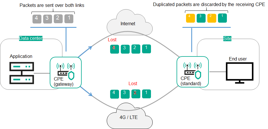
Duplication of traffic packets between CPE devices
Page top
Scenario: Directing application traffic to a transport service
The scenario for directing application traffic to a transport service involves the following steps:
- Creating a transport service
Create a transport service to which you want to direct application traffic. You can use the following instructions to complete this step:
- Creating a traffic classification rule
Create a traffic classification rule to identify the traffic of the application in the overall data stream. When creating a traffic classification rule, you must select the L3 protocol on the L3 fields tab, and select the application whose traffic you want to direct to the transport service on the DPI tab.
If you want to direct traffic of multiple applications to a transport service, you must create create a traffic classification rule for each application.
- Creating a traffic filter
Create a traffic filter to determine if routing the application traffic is allowed. When creating a traffic filter, you must add the traffic classification rules that you created for the application traffic to the traffic filter.
- Creating an ACL interface
Create an ACL interface to apply the traffic filter to traffic that is transmitted through this ACL interface. When creating an ACL interface, you must select a traffic filter that you created for the application traffic.
- Adding the ACL interface to the transport service
Edit the transport service to add the ACL interface that you created for the application traffic. You can use the following instructions to complete this step:
Application traffic is directed to the transport service.
Page top
Managing Point-to-Point (P2P) transport services
To display the table of P2P services, go to the Infrastructure menu section, click Management → Configuration menu next to the controller, and go to the P2P services section. Information about P2P services is displayed in the following columns of the table:
- Name is the name of the P2P service.
- Source contains information about the source service interface of the P2P service:
- Name and DPID of the CPE device on which the service interface was created
- The number of the OpenFlow port which the service interface is mapped to.
- Destination contains information about the destination service interface of the P2P service:
- Name and DPID of the CPE device on which the service interface was created
- The number of the OpenFlow port which the service interface is mapped to.
- QoS is the quality of service rule specified for the source service interface of the P2P service.
- Backup port contains information about the backup service interface of the P2P service:
- Name and DPID of the CPE device on which the service interface was created
- The number of the OpenFlow port which the service interface is mapped to.
- Status is the status of the P2P service:
- Up
- Down
The actions that you can perform with the table are described in the Managing solution component tables instructions.
Creating a P2P service
To create a P2P service:
- In the menu, go to the Infrastructure section.
This opens the resource management page. By default, the Network resources tab is selected, which displays the table of controllers.
- Click Management → Configuration menu next to the controller.
This opens the controller configuration menu. By default, you are taken to the Controller nodes section, which displays a table of controller nodes.
- Go to the P2P services section.
A table of P2P services is displayed.
- In the upper part of the page, click + P2P service.
- This opens a window; in that window, in the Name field, enter the name of the P2P service.
- In the Constraint drop-down list, select the created Manual-TE constraint or threshold constraint that you want to add to the P2P service.
- In the Balancing mode drop-down list, select the balancing mode for distributing traffic among the links:
- Per-flow means the traffic streams (5-Tuple) are distributed among the links in accordance with the link cost. Default value.
- Per-packet means the traffic packets are distributed among the links in accordance with the link cost.
- Broadcast means the traffic packets are duplicated and transmitted simultaneously through all links to avoid loss.
You can manually specify link cost.
- If necessary, in the Description field, enter a brief description of the P2P service.
- In the Switch and Port drop-down lists on the left, select the CPE device and the created service interface that you want to use as the source service interface of the P2P service.
- In the Switch and Port drop-down lists on the right, select the CPE device and the created service interface that you want to use as the destination service interface of the P2P service.
- If you want to display service interfaces that were added to transport services in the Port drop-down lists, select the Show used interfaces check box. This check box is cleared by default.
- If you want to swap the values selected in the Port drop-down lists, select the Switch interfaces check box. This check box is cleared by default.
- If you want to add a reserve service interface of the P2P service source through which traffic is transmitted if the primary service interface fails:
- Select the Use backup interface check box. This check box is cleared by default.
- In the Backup switch and Backup port drop-down lists, select the CPE device and the created service interface that you want to use as the reserve service interface.
- If you want to display service interfaces that were added to transport services in the Backup port drop-down list, select the Show used interfaces check box. This check box is cleared by default.
If the primary source service interface of the P2P service goes up again, the P2P service keeps using the backup source service interface.
- In the Inbound filter drop-down lists on the left and right, select the created traffic filter for the source and destination interfaces of the P2P service.
- In the QoS drop-down list, select the created quality of service rule for the service interface of the P2P service source.
- If you want to track the status of the source and destination service interfaces of the P2P service and when one of the interfaces goes down, automatically disable the other, select the Propagate interface status check box. This check box is cleared by default. This check box cannot be selected when the Use backup interface check box is selected.
When the service interface that was disabled first goes back online, the second service interface that was automatically disabled also resumes operation. This functionality works only on service interfaces with Access traffic classification. You can select the type of traffic classification when creating a service interface.
- Click Create.
The P2P service is created and displayed in the table.
Viewing statistics of a P2P service
To view the statistics of a P2P service:
- In the menu, go to the Infrastructure section.
This opens the resource management page. By default, the Network resources tab is selected, which displays the table of controllers.
- Click Management → Configuration menu next to the controller.
- Go to the P2P services section.
A table of P2P services is displayed.
- Click Management → Statistics next to the P2P service whose statistics you want to view.
This opens a window with statistics of the P2P service.
Page top
Viewing and configuring the display of a P2P service topology
To view and configure the display of a P2P service topology:
- In the menu, go to the Infrastructure section.
This opens the resource management page. By default, the Network resources tab is selected, which displays the table of controllers.
- Click Management → Configuration menu next to the controller.
This opens the controller configuration menu. By default, you are taken to the Controller nodes section, which displays a table of controller nodes.
- Go to the P2P services section.
A table of P2P services is displayed.
- Click Management → Service topology next to the P2P service whose topology you want to view.
This opens a window with the P2P service topology.
- If you need to move CPE devices, do one of the following:
- If you want to manually change the position of CPE devices, click Manual and adjust the position of CPE devices.
- If you want to automatically arrange CPE devices, click Automatically and select one of the following values from the displayed drop-down list:
- Physical simulation — CPE devices are arranged approximately in accordance with their actual location relative to each other, for example:
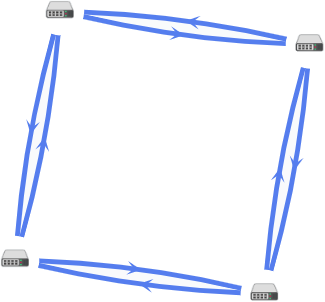
- Random — The arrangement of CPE devices is randomized, for example:
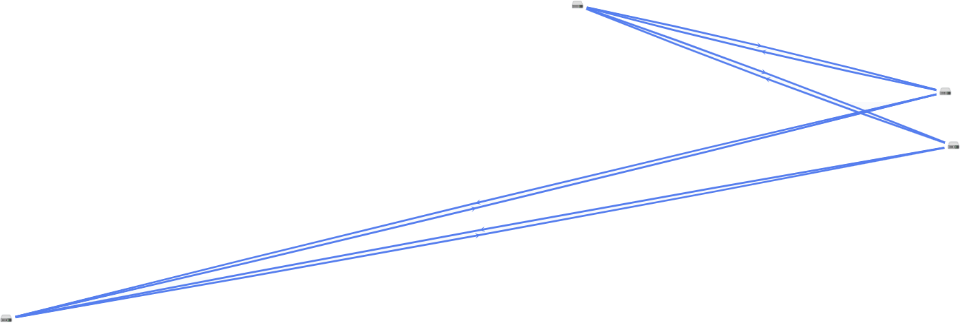
- Circle — CPE devices are arranged in accordance with a ring topology, for example:

- Breadthfirst — CPE devices are arranged horizontally, for example:

- Concentric — CPE devices are arranged concentrically, for example:
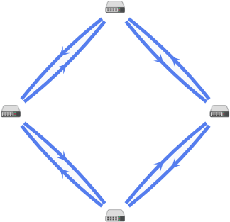
- Grid — CPE devices are arranged in accordance with a grid topology, for example:

- Physical simulation — CPE devices are arranged approximately in accordance with their actual location relative to each other, for example:
- If you want to display information about CPE devices, select the following check boxes:
- Name displays the names of CPE devices.
- IP address displays the IP addresses of CPE devices.
These check boxes are cleared by default.
- If you want to display a segment between two CPE devices:
- Select the Segments check box. This check box is cleared by default.
- In the displayed drop-down lists, select the source and destination CPE devices of the segment.
The segment between the CPE devices is displayed.
Editing a P2P service
To edit a P2P service:
- In the menu, go to the Infrastructure section.
This opens the resource management page. By default, the Network resources tab is selected, which displays the table of controllers.
- Click Management → Configuration menu next to the controller.
This opens the controller configuration menu. By default, you are taken to the Controller nodes section, which displays a table of controller nodes.
- Go to the P2P services section.
A table of P2P services is displayed.
- Click Management → Edit next to the P2P service that you want to edit.
- This opens a window; in that window, if necessary, edit the P2P service settings. For a description of the settings, see the instructions for creating a P2P service.
- Click Save.
The P2P service is modified and updated in the table.
Restarting a P2P service
You can restart a P2P service to restore it in case of malfunctions. When you restart a P2P service, the controller automatically deletes and re-creates the rules associated with this P2P service in the OpenFlow tables of CPE devices. This affects CPE devices whose service interfaces are added to the P2P service.
To restart a P2P service:
- In the menu, go to the Infrastructure section.
This opens the resource management page. By default, the Network resources tab is selected, which displays the table of controllers.
- Click Management → Configuration menu next to the controller.
- Go to the P2P services section.
A table of P2P services is displayed.
- Click Management → Reprovision next to the P2P service that you want to reprovision.
- In the confirmation window, click Reprovision.
The P2P service is restarted.
Page top
Deleting a P2P service
Deleted P2P services cannot be restored
To delete a P2P service:
- In the menu, go to the Infrastructure section.
This opens the resource management page. By default, the Network resources tab is selected, which displays the table of controllers.
- Click Management → Configuration menu next to the controller.
- Go to the P2P services section.
A table of P2P services is displayed.
- Click Management → Delete next to the P2P service that you want to delete.
- To delete the service interfaces added to the P2P service, select the Delete associated service interfaces check box in the confirmation window. This check box is cleared by default.
- Click Delete.
The P2P service is deleted and is no longer displayed in the table.
Page top
Managing Point-to-Multipoint (P2M) transport services
To display the table of P2M services, go to the Infrastructure menu section, click Management → Configuration menu next to the controller, and go to the P2M services section. Information about P2M services is displayed in the following columns of the table:
- Name is the name of the P2M service.
- Mode indicates whether a DFI (Default Forwarding Interface) is used in the P2M service, to which unknown unicast traffic is sent:
- Classic if you do not want to use DFI. Default value.
- DFI with FIB on root and leafs if you want to use DFI on the service interface with the root role.
- DFI with FIB on leaf if you want to use DFI on the service interface with the root role. Service interfaces with the leaf role must be created on the same CPE device. Backup service interfaces with the leaf role must be created on the same CPE device, which must be different from the CPE device on which the primary service interfaces are created.
- MAC age (sec.) is the time period in seconds during which entries are kept in the MAC table of the controller.
- MAC learn mode is the action applied to a series of frames when the first frame is sent to the controller to learn the source MAC address:
- Learn and flood means the controller remembers the MAC address of the source and checks for the presence of the destination MAC address in the MAC table. If the destination MAC address is not in the MAC table, the series of frames is sent to all service interfaces added to the P2M service, except for the service interface on which the series of frames originally arrived.
- Learn and drop means the controller remembers the MAC address of the source and checks for the presence of the destination MAC address in the MAC table. If the destination MAC address is not in the MAC table, the series of frames is dropped.
If the destination MAC address is present in the MAC table, the series of frames is sent to the destination service interface.
- MAC table size is the maximum number of entries in the MAC table on the controller.
- MAC table overload is the policy for processing new MAC addresses when the MAC table of the controller is full:
- Flood means traffic with destination MAC addresses that have not been learned is transmitted as BUM traffic (Broadcast, unknown-unicast, and multicast).
- Drop means that traffic with destination MAC addresses that have not been learned is dropped.
- Endpoints is the information about service interfaces that have been added to the P2M service:
- Names and DPIDs of the CPE devices on which the service interfaces were created
- Numbers of OpenFlow ports which the service interfaces are mapped to
- Roles of the service interfaces:
- Root means the service interface can send traffic to service interfaces with any role.
- Leaf means the service interface can send traffic only to service interfaces with the Root role.
- Status is the status of the P2M service:
- Up
- Down
- Description is a brief description of the P2M service.
The actions you can perform with the table are described in the Managing solution component tables instructions.
Creating a P2M service
To create a P2M service:
- In the menu, go to the Infrastructure section.
This opens the resource management page. By default, the Network resources tab is selected, which displays the table of controllers.
- Click Management → Configuration menu next to the controller.
This opens the controller configuration menu. By default, you are taken to the Controller nodes section, which displays a table of controller nodes.
- Go to the P2M services section.
A table of P2M services is displayed.
- In the upper part of the page, click + P2M service.
- This opens a window; in that window, in the Name field, enter the name of the P2M service.
- In the Constraint drop-down list, select the created Manual-TE constraint or threshold constraint that you want to add to the P2M service.
- In the Balancing mode drop-down list, select the balancing mode for distributing traffic among the links:
- Per-flow means the traffic streams (5-Tuple) are distributed among the links in accordance with the link cost. Default value.
- Per-packet means the traffic packets are distributed among the links in accordance with the link cost.
- Broadcast means the traffic packets are duplicated and transmitted simultaneously through all links to avoid loss.
You can manually specify link cost.
- In the MAC learn mode drop-down list, select the action that you want to apply to a series of frames when the first frame is sent to the controller to learn the source MAC address:
- Learn and flood means the controller remembers the MAC address of the source and checks for the presence of the destination MAC address in the MAC table. If the destination MAC address is not in the MAC table, the series of frames is sent to all service interfaces added to the P2M service, except for the service interface on which the series of frames originally arrived. Default value.
- Learn and drop means the controller remembers the MAC address of the source and checks for the presence of the destination MAC address in the MAC table. If the destination MAC address is not in the MAC table, the series of frames is dropped.
If the destination MAC address is present in the MAC table, the series of frames is sent to the destination service interface.
- In the MAC age (sec.) field, enter the time period in seconds during which entries are kept in the MAC table of the controller. Range of values: 10 to 65,535. Default value:
300. - In the MAC table overload drop-down list, select the policy for processing new MAC addresses when the MAC table of the controller is full:
- Flood means traffic with destination MAC addresses that have not been learned is transmitted as BUM traffic (Broadcast, unknown-unicast, and multicast). Default value.
- Drop means that traffic with destination MAC addresses that have not been learned is dropped.
- In the MAC table size field, enter the maximum number of entries in the MAC table on the controller. Range of values: 0 to 65,535.
0means the number of records in the MAC table of the controller is not limited. Default value:100. - In the Mode drop-down list, select whether the P2M service uses a DFI (Default Forwarding Interface), to which unknown unicast traffic is sent:
- Classic if you do not want to use DFI. Default value.
- DFI with FIB on root and leafs if you want to use DFI on the service interface with the root role.
- DFI with FIB on leaf if you want to use DFI on the service interface with the root role. Service interfaces with the leaf role must be created on the same CPE device. Backup service interfaces with the leaf role must be created on the same CPE device, which must be different from the CPE device on which the primary service interfaces are created.
- If necessary, in the Description field, enter a brief description of the P2M service.
- Click Next to proceed to the next group of settings.
- Add the service interface to the P2M service:
- In the Switch and Port drop-down lists on the right, select the CPE device and the created service interface that you want to add to the P2M service.
- If you want to display service interfaces that were added to transport services in the Port drop-down list, select the Show used interfaces check box. This check box is cleared by default.
- In the QoS drop-down list, select the created quality of service rule for the service interface.
- In the Inbound filter drop-down list, select the created traffic filter for the service interface.
- In the Role drop-down list, select the role of the service interface:
- Root means the service interface can send traffic to service interfaces with any role.
- Leaf means the service interface can send traffic only to service interfaces with the Root role.
- If you want to add a reserve service interface through which traffic is transmitted if the primary service interface fails:
- Select the Use backup interface check box. This check box is cleared by default.
- In the Backup switch and Backup port drop-down lists, select the CPE device and the created service interface that you want to use as the reserve service interface.
- If you want to display service interfaces that were added to transport services in the Backup port drop-down list, select the Show used interfaces check box. This check box is cleared by default.
If the primary service interface goes back online, the P2M service continues to use the backup service interface.
- If you want to assign the DFI role to the service interface, select the Default Forwarding Interface check box. This check box cannot be selected if in the Role drop-down list, you selected Leaf. This check box is cleared by default.
- Click + Add.
The service interface is added and displayed in the lower part of the window. You can add multiple service interfaces or delete a service interface. To delete a service interface, click Delete next to it.
- Click Next to proceed to the next group of settings.
- If you want to add multiple service interfaces to the P2M service at the same time:
- In the Group drop-down list, select the created OpenFlow port group that you want to add to the P2M service. When you save the settings of the P2M service, service interfaces are automatically created that are mapped to OpenFlow ports in the OpenFlow port group, and then these service interfaces are automatically added to the P2M service.
- In the QoS drop-down list, select the created quality of service rule for automatically created service interfaces mapped to OpenFlow ports.
- In the VLAN ID field, enter the outer VLAN tag value for automatically created service interfaces mapped to OpenFlow ports. Service interfaces with the VLAN traffic classification type can only be created automatically. The same outer VLAN tag is assigned to each service interface.
- In the Role drop-down list, select the role for automatically created service interfaces mapped to OpenFlow ports:
- Root means the service interface can send traffic to service interfaces with any role.
- Leaf means the service interface can send traffic only to service interfaces with the Root role.
- Click + Add.
The OpenFlow group is added and displayed in the lower part of the window. You can add multiple OpenFlow port groups or delete an OpenFlow port group. To delete a group of OpenFlow ports, click Delete next to it.
- Click Create.
The P2M service is created and displayed in the table.
Viewing statistics of a P2M service
To view the statistics of a P2M service:
- In the menu, go to the Infrastructure section.
This opens the resource management page. By default, the Network resources tab is selected, which displays the table of controllers.
- Click Management → Configuration menu next to the controller.
- Go to the P2M services section.
A table of P2M services is displayed.
- Click Management → Statistics next to the P2M service whose statistics you want to view.
This opens a window with statistics of the P2M service.
Page top
Viewing the MAC table of a P2M service
To view the MAC table of a P2M service:
- In the menu, go to the Infrastructure section.
This opens the resource management page. By default, the Network resources tab is selected, which displays the table of controllers.
- Click Management → Configuration menu next to the controller.
- Go to the P2M services section.
A table of P2M services is displayed.
- Click Management → MAC table next to the P2M service whose MAC table you want to view.
This opens a window with the MAC table of the P2M service.
- If you want to find a specific MAC address, enter it in the field and click Find by MAC.
- If you want to clear the MAC table, click Clear.
Viewing and configuring the display of a P2M service topology
To view and configure the display of a P2M service topology:
- In the menu, go to the Infrastructure section.
This opens the resource management page. By default, the Network resources tab is selected, which displays the table of controllers.
- Click Management → Configuration menu next to the controller.
This opens the controller configuration menu. By default, you are taken to the Controller nodes section, which displays a table of controller nodes.
- Go to the P2M services section.
A table of P2M services is displayed.
- Click Management → Service topology next to the P2M service whose topology you want to view.
This opens a window with the P2M service topology.
- If you need to move CPE devices, do one of the following:
- If you want to manually change the position of CPE devices, click Manual and adjust the position of CPE devices.
- If you want to automatically arrange CPE devices, click Automatically and select one of the following values from the displayed drop-down list:
- Physical simulation — CPE devices are arranged approximately in accordance with their actual location relative to each other, for example:
- Random — The arrangement of CPE devices is randomized, for example:
- Circle — CPE devices are arranged in accordance with a ring topology, for example:
- Breadthfirst — CPE devices are arranged horizontally, for example:
- Concentric — CPE devices are arranged concentrically, for example:
- Grid — CPE devices are arranged in accordance with a grid topology, for example:
- Physical simulation — CPE devices are arranged approximately in accordance with their actual location relative to each other, for example:
- If you want to display information about CPE devices, select the following check boxes:
- Name displays the names of CPE devices.
- IP address displays the IP addresses of CPE devices.
These check boxes are cleared by default.
- If you want to display a segment between two CPE devices:
- Select the Segments check box. This check box is cleared by default.
- In the displayed drop-down lists, select the source and destination CPE devices of the segment.
The segment between the CPE devices is displayed.
Editing a P2M service
To edit a P2M service:
- In the menu, go to the Infrastructure section.
This opens the resource management page. By default, the Network resources tab is selected, which displays the table of controllers.
- Click Management → Configuration menu next to the controller.
This opens the controller configuration menu. By default, you are taken to the Controller nodes section, which displays a table of controller nodes.
- Go to the P2M services section.
A table of P2M services is displayed.
- Click Management → Edit next to the P2M service that you want to edit.
- This opens a window; in that window, if necessary, edit the P2M service settings. For a description of the settings, see the instructions for creating a P2M service.
- Click Save.
The P2M service is modified and updated in the table.
Restarting a P2M service
You can restart a P2M service to restore it in case of malfunctions. When you restart a P2M service, the controller automatically deletes and re-creates the rules associated with this P2M service in the OpenFlow tables of CPE devices. This affects CPE devices whose service interfaces are added to the P2M service.
To restart a P2M service:
- In the menu, go to the Infrastructure section.
This opens the resource management page. By default, the Network resources tab is selected, which displays the table of controllers.
- Click Management → Configuration menu next to the controller.
- Go to the P2M services section.
A table of P2M services is displayed.
- Click Management → Reprovision next to the P2M service that you want to reprovision.
- In the confirmation window, click Confirm.
The P2M service is restarted.
Page top
Deleting a P2M service
Deleted P2M services cannot be restored.
To delete a P2M service:
- In the menu, go to the Infrastructure section.
This opens the resource management page. By default, the Network resources tab is selected, which displays the table of controllers.
- Click Management → Configuration menu next to the controller.
- Go to the P2M services section.
A table of P2M services is displayed.
- Click Management → Delete next to the P2M service that you want to delete.
- If you want to delete the service interfaces added to the P2M service, select the Delete associated service interfaces check box in the confirmation window. This check box is cleared by default.
- Click Delete.
The P2M service is deleted and is no longer displayed in the table.
Page top
Managing Multipoint-to-Multipoint (M2M) transport services
To display the table of M2M services, go to the Infrastructure menu section, click Management → Configuration menu next to the controller, and go to the M2M services section. Information about M2M services is displayed in the following columns of the table:
- Name is the name of the M2M service.
- MAC age (sec.) is the time period in seconds during which entries are kept in the MAC table of the controller.
- MAC learn mode is the action applied to a series of frames when the first frame is sent to the controller to learn the source MAC address:
- MAC table size is the maximum number of entries in the MAC table on the controller.
- MAC table overload is the policy for processing new MAC addresses when the MAC table of the controller is full:
- Flood means traffic with destination MAC addresses that have not been learned is transmitted as BUM traffic (Broadcast, unknown-unicast, and multicast). Default value.
- Drop means that traffic with destination MAC addresses that have not been learned is dropped.
- Endpoints is the information about service interfaces that have been added to the M2M service:
- Names and DPIDs of the CPE devices on which the service interfaces were created
- Numbers of OpenFlow ports which the service interfaces are mapped to
- Roles of the service interfaces.
- Status is the status of the M2M service:
- Up
- Down
- Description is a brief description of the M2M service.
The actions you can perform with the table are described in the Managing solution component tables instructions.
Creating an M2M service
To create an M2M service:
- In the menu, go to the Infrastructure section.
This opens the resource management page. By default, the Network resources tab is selected, which displays the table of controllers.
- Click Management → Configuration menu next to the controller.
This opens the controller configuration menu. By default, you are taken to the Controller nodes section, which displays a table of controller nodes.
- Go to the M2M services section.
A table of M2M services is displayed.
- In the upper part of the page, click + M2M service.
- This opens a window; in that window, in the Name field, enter the name of the M2M service.
- In the Constraint drop-down list, select the created Manual-TE constraint or threshold constraint that you want to add to the M2M service.
- In the Balancing mode drop-down list, select the balancing mode for balancing traffic across links:
- Per-flow means the traffic streams (5-Tuple) are distributed among the links in accordance with the link cost. Default value.
- Per-packet means the traffic packets are distributed among the links in accordance with the link cost.
- Broadcast means the traffic packets are duplicated and transmitted simultaneously through all links to avoid loss.
You can manually specify link cost.
- In the MAC learn mode drop-down list, select the action that you want to apply to a series of frames when the first frame is sent to the controller to learn the source MAC address:
- Learn and flood means the controller remembers the MAC address of the source and checks for the presence of the destination MAC address in the MAC table. If the destination MAC address is not in the MAC table, the series of frames is sent to all service interfaces added to the M2M service, except for the service interface on which the series of frames originally arrived. Default value.
- Learn and drop means the controller remembers the MAC address of the source and checks for the presence of the destination MAC address in the MAC table. If the destination MAC address is not in the MAC table, the series of frames is dropped.
If the destination MAC address is present in the MAC table, the series of frames is sent to the destination service interface.
- In the MAC age (sec.) field, enter the time period in seconds during which entries are kept in the MAC table of the controller. Range of values: 10 to 65,535. Default value:
300. - In the MAC table overload drop-down list, select the policy for processing new MAC addresses when the MAC table of the controller is full:
- Flood means traffic with destination MAC addresses that have not been learned is transmitted as BUM traffic (Broadcast, unknown-unicast, and multicast). Default value.
- Drop means that traffic with destination MAC addresses that have not been learned is dropped.
- In the MAC table size field, enter the maximum number of entries in the MAC table on the controller. Range of values: 0 to 65,535.
0means the number of records in the MAC table of the controller is not limited. Default value:100. - If necessary, in the Description field, enter a brief description of the M2M service.
- Click Next to proceed to the next group of settings.
- Add the service interface to the M2M service:
- In the Switch and Port drop-down lists on the right, select the CPE device and the created service interface that you want to add to the M2M service.
- If you want to display service interfaces that were added to transport services in the Port drop-down list, select the Show used interfaces check box. This check box is cleared by default.
- In the QoS drop-down list, select the created quality of service rule for the service interface.
- In the Inbound filter drop-down list, select the created traffic filter for the service interface.
- If you want to add a reserve service interface through which traffic is transmitted if the primary service interface fails:
- Select the Use backup interface check box. This check box is cleared by default.
- In the Backup switch and Backup port drop-down lists, select the CPE device and the created service interface that you want to use as the reserve service interface.
- If you want to display service interfaces that were added to transport services in the Backup port drop-down list, select the Show used interfaces check box. This check box is cleared by default.
If the primary service interface goes back online, the M2M service continues to use the backup service interface.
- Click + Add.
The service interface is added and displayed in the lower part of the window. You can add multiple service interfaces or delete a service interface. To delete a service interface, click Delete next to it.
- Click Next to proceed to the next group of settings.
- If you want to add multiple service interfaces to the M2M service at the same time:
- In the Group drop-down list, select the created OpenFlow port group that you want to add to the M2M service. When you save the settings of the M2M service, service interfaces are automatically created that are mapped to OpenFlow ports in the OpenFlow port group, and then these service interfaces are automatically added to the M2M service.
- In the QoS drop-down list, select the created quality of service rule for automatically created service interfaces mapped to OpenFlow ports.
- In the VLAN ID field, enter the outer VLAN tag value for automatically created service interfaces mapped to OpenFlow ports. Service interfaces with the VLAN classification type can only be created automatically. The same outer VLAN tag is assigned to each service interface.
- Click + Add.
The OpenFlow group is added and displayed in the lower part of the window. You can add multiple OpenFlow port groups or delete an OpenFlow port group. To delete a group of OpenFlow ports, click Delete next to it.
- Click Create.
The M2M service is created and displayed in the table.
Viewing statistics of an M2M service
To view the statistics of an M2M service:
- In the menu, go to the Infrastructure section.
This opens the resource management page. By default, the Network resources tab is selected, which displays the table of controllers.
- Click Management → Configuration menu next to the controller.
- Go to the M2M services section.
A table of M2M services is displayed.
- Click Management → Statistics next to the M2M service whose statistics you want to view.
This opens a window with statistics of the M2M service.
Page top
Viewing the MAC table of an M2M service
To view the MAC table of an M2M service:
- In the menu, go to the Infrastructure section.
This opens the resource management page. By default, the Network resources tab is selected, which displays the table of controllers.
- Click Management → Configuration menu next to the controller.
- Go to the M2M services section.
A table of M2M services is displayed.
- Click Management → MAC table next to the M2M service whose MAC table you want to view.
This opens a window with the MAC table of the M2M service.
- If you want to find a specific MAC address, enter it in the field and click Find by MAC.
- If you want to clear the MAC table, click Clear.
Viewing and configuring the display of an M2M service topology
To view and configure the display of an M2M service topology:
- In the menu, go to the Infrastructure section.
This opens the resource management page. By default, the Network resources tab is selected, which displays the table of controllers.
- Click Management → Configuration menu next to the controller.
This opens the controller configuration menu. By default, you are taken to the Controller nodes section, which displays a table of controller nodes.
- Go to the M2M services section.
A table of M2M services is displayed.
- Click Management → Service topology next to the M2M service whose topology you want to view.
This opens a window with the M2M service topology.
- If you need to move CPE devices, do one of the following:
- If you want to manually change the position of CPE devices, click Manual and adjust the position of CPE devices.
- If you want to automatically arrange CPE devices, click Automatically and select one of the following values from the displayed drop-down list:
- Physical simulation — CPE devices are arranged approximately in accordance with their actual location relative to each other, for example:
- Random — The arrangement of CPE devices is randomized, for example:
- Circle — CPE devices are arranged in accordance with a ring topology, for example:
- Breadthfirst — CPE devices are arranged horizontally, for example:
- Concentric — CPE devices are arranged concentrically, for example:
- Grid — CPE devices are arranged in accordance with a grid topology, for example:
- Physical simulation — CPE devices are arranged approximately in accordance with their actual location relative to each other, for example:
- If you want to display information about CPE devices, select the following check boxes:
- Name displays the names of CPE devices.
- IP address displays the IP addresses of CPE devices.
These check boxes are cleared by default.
- If you want to display a segment between two CPE devices:
- Select the Segments check box. This check box is cleared by default.
- In the displayed drop-down lists, select the source and destination CPE devices of the segment.
The segment between the CPE devices is displayed.
Editing an M2M service
To edit an M2M service:
- In the menu, go to the Infrastructure section.
This opens the resource management page. By default, the Network resources tab is selected, which displays the table of controllers.
- Click Management → Configuration menu next to the controller.
This opens the controller configuration menu. By default, you are taken to the Controller nodes section, which displays a table of controller nodes.
- Go to the M2M services section.
A table of M2M services is displayed.
- Click Management → Edit next to the M2M service that you want to edit.
- This opens a window; in that window, if necessary, edit the M2M service settings. For a description of the settings, see the instructions for creating an M2M service.
- Click Save.
The M2M service is modified and updated in the table.
Restarting an M2M service
You can restart an M2M service to restore it in case of malfunctions. When you restart an M2M service, the controller automatically deletes and re-creates the rules associated with this M2M service in the OpenFlow tables of CPE devices. This affects CPE devices whose service interfaces are added to the M2M service.
To restart an M2M service:
- In the menu, go to the Infrastructure section.
This opens the resource management page. By default, the Network resources tab is selected, which displays the table of controllers.
- Click Management → Configuration menu next to the controller.
- Go to the M2M services section.
A table of M2M services is displayed.
- Click Management → Reprovision next to the M2M service that you want to reprovision.
- In the confirmation window, click Confirm.
The M2M service is restarted.
Page top
Deleting an M2M service
Deleted M2M services cannot be restored.
To delete an M2M service:
- In the menu, go to the Infrastructure section.
This opens the resource management page. By default, the Network resources tab is selected, which displays the table of controllers.
- Click Management → Configuration menu next to the controller.
- Go to the M2M services section.
A table of M2M services is displayed.
- Click Management → Delete next to the M2M service that you want to delete.
- If you want to delete the service interfaces added to the M2M service, select the Delete associated service interfaces check box in the confirmation window. This check box is cleared by default.
- Click Delete.
The M2M service is deleted and is no longer displayed in the table.
Page top
Managing L3 VPN transport services
To display the table of L3 VPN services, go to the Infrastructure menu section, click Management → Configuration menu next to the controller, and go to the L3 VPN services section. Information about L3 VPN services is displayed in the following columns of the table:
- Name is the of the L3 VPN service.
- Type is the topology type of the L3 VPN service.
- Inter-spoke through hub indicates whether communication is possible between spoke sites through the hub site:
- Yes
- No
- Endpoints is the information about the L3 interfaces that have been added to the L3 VPN service:
- If the L3 interfaces are mapped to M2M services, the M2M service names are displayed.
- If the L3 interfaces are mapped to service interfaces, the following information is displayed:
- Names and DPIDs of the CPE devices on which the service interfaces were created
- Numbers of OpenFlow ports which the service interfaces are mapped to
- Quality of service rules specified for the service interfaces
- Traffic filters specified for the service interfaces
- IP prefixes of the L3 interfaces
- MAC addresses of the L3 interfaces
- Time period in seconds during which entries are kept in the ARP table on the controller
- Routes is the information about static routes that have been added to the L3 VPN service:
- Destination IPv4 prefixes of static routes
- Gateway IPv4 addresses for routing traffic packets to destination IPv4 prefixes of static routes
- L3 interfaces behind which the destination IPv4 prefixes of static routes are
- Metrics of the static routes
- DHCP servers are IPv4 addresses of DHCP servers specified for the L3 VPN service.
- Status is the status of the L3 VPN service:
- Up
- Down
- Errors are errors that occurred while the L3 VPN service was running.
The actions you can perform with the table are described in the Managing solution component tables instructions.
Creating an L3 VPN service
To create an L3 VPN service:
- In the menu, go to the Infrastructure section.
This opens the resource management page. By default, the Network resources tab is selected, which displays the table of controllers.
- Click Management → Configuration menu next to the controller.
This opens the controller configuration menu. By default, you are taken to the Controller nodes section, which displays a table of controller nodes.
- Go to the L3 VPN services section.
A table of L3 VPN services is displayed.
- In the upper part of the page, click + L3 VPN service.
- This opens a window; in that window, in the Name field, enter the name of the L3 VPN service.
- In the Constraint drop-down list, select the created Manual-TE constraint or threshold constraint that you want to add to the L3 VPN service.
- In the Balancing mode drop-down list, select the balancing mode for balancing traffic across links:
- Per-flow means the traffic streams (5-Tuple) are distributed among the links in accordance with the link cost. Default value.
- Per-packet means the traffic packets are distributed among the links in accordance with the link cost.
- Broadcast means the traffic packets are duplicated and transmitted simultaneously through all links to avoid loss.
You can manually specify link cost.
- Click Next to proceed to the next group of settings.
- Add the L3 interface to the L3 VPN service:
- In the Mode drop-down list, select the type of the L3 interface:
- M2M service means the L3 interface is mapped to an M2M service.
- Service interface means the L3 interface is mapped to a service interface.
- If in the Mode drop-down list, you selected M2M service, in the M2M service drop-down list, select the created M2M service mapped to the L3 interface.
- If in the Mode drop-down list, you selectedService interface, configure the service interface:
- In the Switch and Port drop-down lists, select the CPE device and the created service interface to which the L3 interface is mapped.
- In the QoS drop-down list, select the created quality of service rule for the L3 interface.
- In the Inbound filter drop-down list, select the created traffic filter for the L3 interface.
- If you want to display service interfaces that were added to transport services in the Port drop-down list, select the Show used interfaces check box. This check box is cleared by default.
- In the IP field, enter the IP address of the L3 interface.
- In the Prefix length field, enter the length of the L3 interface prefix. Range of values: 0 to 32.
- In the MAC address field, enter the MAC address of the L3 interface. You can generate a MAC address by clicking Generate.
- In the ARP age (sec.) field, enter the time period in seconds during which entries are kept in the ARP table on the L3 VPN service. Range of values: 1 to 65,535. Default value:
200. - Click + Add.
The L3 interface is added and displayed in the lower part of the window. You can add multiple L3 interfaces or delete an L3 interface. To delete an L3 interface, click Delete next to it.
- In the Mode drop-down list, select the type of the L3 interface:
- Click Next to proceed to the next group of settings.
- If you want to add a static route to the L3 VPN service:
- In the IP field, enter the destination IPv4 address of the static route.
- In the Prefix length field, enter the length of the IPv4 prefix of the static route. Range of values: 0 to 32.
- In the SVI drop-down list, select the added L3 interface followed by the IPv4 prefix of the static route destination. You added an L3 interface at step 9 of these instructions.
- In the Gateway field, enter the IPv4 address of the gateway for routing traffic packets to the IPv4 prefix of the static route destination.
- In the Metric field, enter a metric for the static route. Default value:
0. - Click + Add.
The static route is added and displayed in the lower part of the window. You can add multiple static routes or delete a static route. To delete a static route, click Delete next to it.
- Click Next to proceed to the next group of settings.
- Click Create.
The L3 VPN service is created and displayed in the table.
Managing the ARP table of an L3 VPN service
To display the ARP table of the L3 VPN service, go to the Infrastructure section, click Management → Configuration menu next to the controller, go to the L3 VPN services section, and click Management → ARP table next to the L3 VPN service. Information about records is displayed in the following columns of the table:
- IP is the IP address of the service interface.
- MAC is the MAC address of the service interface.
- Service interface is the information about the service interface:
- Name and DPID of the CPE device on which the service interface was created
- Number of the OpenFlow port which the service interface is mapped to
- Timeout maximum life (sec.) is the time in seconds that has elapsed since the record was created.
The actions you can perform with the table are described in the Managing solution component tables instructions.
Creating a static record in the ARP table of an L3 VPN service
To create a static record in the ARP table of an L3 VPN service:
- In the menu, go to the Infrastructure section.
This opens the resource management page. By default, the Network resources tab is selected, which displays the table of controllers.
- Click Management → Configuration menu next to the controller.
- Go to the L3 VPN services section.
A table of L3 VPN services is displayed.
- Click Management → ARP table next to the L3 VPN service in whose ARP table you want to create a static record.
The page with the ARP table of the L3 VPN service is displayed.
- In the upper part of the page, click + Static ARP record.
- This opens a window; in that window, in the Switch and Port drop-down lists, select the CPE device and the created service interface for which you want to specify an IP address and a MAC address.
- In the IP address field, enter the IP address of the service interface.
- In the MAC field, enter the MAC address of the service interface.
- Click Create.
The static record is created and displayed in the ARP table of the L3 VPN service.
Page top
Editing a static record in the ARP table of an L3 VPN service
To edit a static record in the ARP table of an L3 VPN service:
- In the menu, go to the Infrastructure section.
This opens the resource management page. By default, the Network resources tab is selected, which displays the table of controllers.
- Click Management → Configuration menu next to the controller.
- Go to the L3 VPN services section.
A table of L3 VPN services is displayed.
- Click Management → ARP table next to the L3 VPN service in whose ARP table you want to edit a static record.
The page with the ARP table of the L3 VPN service is displayed.
- Click Management → Edit next to the static record that you want to edit.
- This opens a window; in that window, if necessary, edit the IP address and/or MAC address of the service interface.
- Click Save.
The static record is modified and updated in the table.
Page top
Deleting a static record in the ARP table of an L3 VPN service
Deleted static records in the ARP table of an L3 VPN service cannot be restored.
To delete a static record in the ARP table of an L3 VPN service:
- In the menu, go to the Infrastructure section.
This opens the resource management page. By default, the Network resources tab is selected, which displays the table of controllers.
- Click Management → Configuration menu next to the controller.
This opens the controller configuration menu. By default, you are taken to the Controller nodes section, which displays a table of controller nodes.
- Go to the L3 VPN services section.
A table of L3 VPN services is displayed.
- Click Management → ARP table next to the L3 VPN service in whose ARP table you want to delete a static record.
The page with the ARP table of the L3 VPN service is displayed.
- Click Management → Delete next to the static record that you want to delete.
- In the confirmation window, click Delete.
The static record is deleted and no longer displayed in the table.
Page top
Viewing the routing and forwarding table of an L3 VPN service
To view the routing and forwarding table of an L3 VPN service:
- In the menu, go to the Infrastructure section.
This opens the resource management page. By default, the Network resources tab is selected, which displays the table of controllers.
- Click Management → Configuration menu next to the controller.
- Go to the L3 VPN services section.
A table of L3 VPN services is displayed.
- Click Management → Routing table next to the L3 VPN service whose routing table you want to view.
This opens a window with the routing and forwarding table of the L3 VPN service.
Page top
Editing an L3 VPN service
To edit an L3 VPN service:
- In the menu, go to the Infrastructure section.
This opens the resource management page. By default, the Network resources tab is selected, which displays the table of controllers.
- Click Management → Configuration menu next to the controller.
This opens the controller configuration menu. By default, you are taken to the Controller nodes section, which displays a table of controller nodes.
- Go to the L3 VPN services section.
A table of L3 VPN services is displayed.
- Click Management → Edit next to the L3 VPN service that you want to edit.
- This opens a window; in that window, if necessary, edit the L3 VPN service settings. For a description of the settings, see the instructions for creating an L3 VPN service.
- Click Save.
The L3 VPN service is modified and updated in the table.
Restarting an L3 VPN service
You can restart an L3 VPN service to restore it in case of malfunctions. When you restart an L3 VPN service, the controller automatically deletes and re-creates the rules associated with this L3 VPN service in the OpenFlow tables of CPE devices. This affects CPE devices whose service interfaces are added to the L3 VPN service.
To restart an L3 VPN service:
- In the menu, go to the Infrastructure section.
This opens the resource management page. By default, the Network resources tab is selected, which displays the table of controllers.
- Click Management → Configuration menu next to the controller.
- Go to the L3 VPN services section.
A table of L3 VPN services is displayed.
- Click Management → Reprovision next to the L3 VPN service that you want to reprovision.
- In the confirmation window, click Confirm.
The L3 VPN service is restarted.
Page top
Deleting an L3 VPN service
Deleted L3 VPN services cannot be restored.
To delete an L3 VPN service:
- In the menu, go to the Infrastructure section.
This opens the resource management page. By default, the Network resources tab is selected, which displays the table of controllers.
- Click Management → Configuration menu next to the controller.
- Go to the L3 VPN services section.
A table of L3 VPN services is displayed.
- Click Management → Delete next to the L3 VPN service that you want to delete.
- If you want to delete the service interfaces added to the L3 VPN service, select the Delete associated service interfaces check box in the confirmation window. This check box is cleared by default.
- Click Delete.
The L3 VPN service is deleted and is no longer displayed in the table.
Page top
Managing IP multicast transport services
To display the table of IP multicast services, go to the Infrastructure menu section, click Management → Configuration menu next to the controller, and go to the IP multicast services section. Information about IP multicast services is displayed in the following columns of the table:
- Name is the name of the IP multicast service.
- Source port contains information about the source service interface of the IP multicast service:
- Name and DPID of the CPE device on which the service interface was created
- The number of the OpenFlow port which the service interface is mapped to.
- Backup source port contains information about the backup source service interface of the IP multicast service:
- Name and DPID of the CPE device on which the service interface was created
- The number of the OpenFlow port which the service interface is mapped to.
- Querier IP is the IP address of the source service interface of the IP multicast service.
- Consumer ports contains information about the destination service interfaces of the IP multicast service:
- Names and DPIDs of the CPE devices on which the service interfaces were created
- Numbers of OpenFlow ports which the service interfaces are mapped to
- Groups contains information about multicast groups that have been added to the IP multicast service:
- IP addresses of multicast groups
- Prefix lengths of multicast groups
- Guaranteed bandwidth for multicast groups
- Status is the status of the IP multicast service:
- Up
- Down
- Errors are errors that occurred while the IP multicast service was running.
The actions you can perform with the table are described in the Managing solution component tables instructions.
Creating an IP multicast service
To create an IP multicast service:
- In the menu, go to the Infrastructure section.
This opens the resource management page. By default, the Network resources tab is selected, which displays the table of controllers.
- Click Management → Configuration menu next to the controller.
This opens the controller configuration menu. By default, you are taken to the Controller nodes section, which displays a table of controller nodes.
- Go to the IP multicast services section.
A table of IP multicast services is displayed.
- In the upper part of the page, click + IP multicast service.
- This opens a window; in that window, in the Name field, enter the name of the IP multicast service.
- In the Switch and Port drop-down lists, select the CPE device and the created service interface that you want to use as the source service interface of the IP multicast service.
- If you want to display service interfaces that were added to transport services in the Source port drop-down list, select the Show used interfaces check box. This check box is cleared by default.
- In the Querier IP field, enter the IP address of the source service interface of the IP multicast service.
- If you want to add a reserve service interface of the IP multicast service source through which traffic is transmitted if the primary service interface fails:
- Select the Use backup interface check box. This check box is cleared by default.
- In the Backup switch and Backup port drop-down lists, select the CPE device and the created service interface that you want to use as the reserve service interface.
- If you want to display service interfaces that were added to transport services in the Backup port drop-down list, select the Show used interfaces check box. This check box is cleared by default.
- If you want the IP multicast service to use the primary source service interface again when that service interface goes up again, select the Recovery auto-return check box. This check box is cleared by default.
- If you want the multicast traffic distribution tree to be built on the backup service interface, select the Backup multicast tree check box. As long as the primary service interface remains active, traffic packets on the backup service interface are dropped. This check box is selected by default.
- Select the IGMP proxy check box to use an IGMP proxy server. This allows you to maintain traffic transmission to active multicast groups to which at least one destination service interface of the IP multicast service is connected. This check box is cleared by default.
- In the QoS drop-down list, select the created quality of service rule for the service interface of the IP multicast service source.
- Click Next to proceed to the next group of settings.
- Add the destination service interface to the IP multicast service:
- In the Switch and Port drop-down lists, select the CPE device and the created service interface that you want to use as the destination service interface of the IP multicast service.
- If you want to display service interfaces that were added to transport services in the Port drop-down list, select the Show used interfaces check box. This check box is cleared by default.
- Click + Add.
The service interface is added and displayed in the lower part of the window. You can add multiple service interfaces or delete a service interface. To delete a service interface, click Delete next to it.
- Click Next to proceed to the next group of settings.
- Add the multicast group to the IP multicast service:
- In the IP address field, enter the IP address of the multicast group. Range of values: 224.0.0.0 to 239.255.255.255.
- In the Mask drop-down list, select the length of the multicast group prefix. Range of values: 24 to 32.
- In the GBR drop-down list, select the guaranteed bit rate (GBR) for the multicast group.
- Click + Add.
The multicast group is added and displayed in the lower part of the window. You can add multiple multicast groups or delete a multicast group. To delete a multicast group, click Delete next to it.
- Click Create.
The IP multicast service is created and displayed in the table.
Viewing statistics of an IP multicast service
To view the statistics of an IP multicast service:
- In the menu, go to the Infrastructure section.
This opens the resource management page. By default, the Network resources tab is selected, which displays the table of controllers.
- Click Management → Configuration menu next to the controller.
- Go to the IP multicast services section.
A table of IP multicast services is displayed.
- Click Management → Statistics next to the IP multicast service whose statistics you want to view.
This opens a window with statistics of the IP multicast service.
Page top
Editing an IP multicast service
To edit an IP multicast service:
- In the menu, go to the Infrastructure section.
This opens the resource management page. By default, the Network resources tab is selected, which displays the table of controllers.
- Click Management → Configuration menu next to the controller.
This opens the controller configuration menu. By default, you are taken to the Controller nodes section, which displays a table of controller nodes.
- Go to the IP multicast services section.
A table of IP multicast services is displayed.
- Click Management → Edit source interfaces, Edit consumer interfaces, or Edit multicast groups next to the IP multicast service that you want to edit.
- This opens a window; in that window, if necessary, edit the IP multicast service settings. For a description of the settings, see the instructions for creating an IP multicast service.
- Click Save.
The IP multicast service is modified and updated in the table.
Deleting an IP multicast service
Deleted IP multicast services cannot be restored.
To delete an IP multicast service:
- In the menu, go to the Infrastructure section.
This opens the resource management page. By default, the Network resources tab is selected, which displays the table of controllers.
- Click Management → Configuration menu next to the controller.
- Go to the IP multicast services section.
A table of IP multicast services is displayed.
- Click Management → Delete next to the IP multicast service that you want to delete.
- If you want to delete the service interfaces added to the IP multicast service, select the Delete associated service interfaces check box in the confirmation window. This check box is cleared by default.
- Click Delete.
The IP multicast service is deleted and is no longer displayed in the table.
Page top
Managing transport services in an SD-WAN instance template
To display the table of P2M services and M2M services in an SD-WAN instance template, go to the SD-WAN → SD-WAN instance templates section, click the SD-WAN instance template, and select the Transport services tab. Information about P2M services and M2M services is displayed in the following columns of the table:
- Name is the name of the P2M service or M2M service.
- Type is the type of transport service:
- P2M
- M2M
- Management tunnel indicates whether the P2M service or M2M service is a management service:
- Yes
- No
- Mode indicates whether a DFI (Default Forwarding Interface) is used in the P2M service, to which unknown unicast traffic is sent:
- Classic if you do not want to use DFI. Default value.
- DFI with FIB on root and leafs if you want to use DFI on the service interface with the root role.
- DFI with FIB on leaf if you want to use DFI on the service interface with the root role. Service interfaces with the leaf role must be created on the same CPE device. Backup service interfaces with the leaf role must be created on the same CPE device, which must be different from the CPE device on which the primary service interfaces are created.
The value in this column is displayed only if the value in the Type column is P2M.
- MAC age (sec.) is the time period in seconds during which entries are kept in the MAC table of the controller.
- MAC learn mode is the action applied to a series of frames when the first frame is sent to the controller to learn the source MAC address:
- Learn and flood means the controller remembers the MAC address of the source and checks for the presence of the destination MAC address in the MAC table. If the destination MAC address is not in the MAC table, the series of frames is sent to all service interfaces added to the M2M service, except for the service interface on which the series of frames originally arrived.
- Learn and drop means the controller remembers the MAC address of the source and checks for the presence of the destination MAC address in the MAC table. If the destination MAC address is not in the MAC table, the series of frames is dropped.
If the destination MAC address is present in the MAC table, the series of frames is sent to the destination service interface.
- MAC table size is the maximum number of entries in the MAC table on the controller.
- MAC table overload is the policy for processing new MAC addresses when the MAC table of the controller is full:
- Flood means traffic with destination MAC addresses that have not been learned is transmitted as BUM traffic (Broadcast, unknown-unicast, and multicast). Default value.
- Drop means that traffic with destination MAC addresses that have not been learned is dropped.
To display a list of L3 VPN services, select the L3 services tab.
Creating a P2M service or an M2M service in an SD-WAN instance template
To create a P2M service or an M2M service in an SD-WAN instance template:
- In the menu, go to the SD-WAN → SD-WAN instance templates section.
A table of SD-WAN instance templates is displayed.
- Click the SD-WAN instance template in which you want to create a P2M service or an M2M service.
The settings area is displayed in the lower part of the page. You can expand the settings area to fill the entire page by clicking the expand icon
. By default, the Information tab is selected, which displays the name of the SD-WAN instance template. - Select the Transport services tab.
The X2M services tab with the table of P2M services and M2M services is selected by default.
- Click + Transport service.
- This opens a window; in that window, in the Name field, enter the name of the P2M or M2M service.
- In the Type drop-down list, select the type of the transport service:
- P2M If you select this option in the Mode drop-down list, select whether the P2M service uses a DFI (Default Forwarding Interface), to which unknown unicast traffic is sent:
- Classic if you do not want to use DFI. Default value.
- DFI with FIB on root and leafs if you want to use DFI on the service interface with the root role.
- DFI with FIB on leaf if you want to use DFI on the service interface with the root role. Service interfaces with the leaf role must be created on the same CPE device. Backup service interfaces with the leaf role must be created on the same CPE device, which must be different from the CPE device on which the primary service interfaces are created.
- M2M
- P2M If you select this option in the Mode drop-down list, select whether the P2M service uses a DFI (Default Forwarding Interface), to which unknown unicast traffic is sent:
- If you want to make a P2M or M2M service the management service, select the Management tunnel check box. This check box is cleared by default. Only one transport service can be the management service.
- In the MAC learn mode drop-down list, select the action that you want to apply to a series of frames when the first frame is sent to the controller to learn the source MAC address:
- Learn and flood means the controller remembers the MAC address of the source and checks for the presence of the destination MAC address in the MAC table. If the destination MAC address is not in the MAC table, the series of frames is sent to all service interfaces added to the P2M service, except for the service interface on which the series of frames originally arrived. Default value.
- Learn and drop means the controller remembers the MAC address of the source and checks for the presence of the destination MAC address in the MAC table. If the destination MAC address is not in the MAC table, the series of frames is dropped.
If the destination MAC address is present in the MAC table, the series of frames is sent to the destination service interface.
- In the MAC table size field, enter the maximum number of entries in the MAC table on the controller. Range of values: 0 to 65,535.
0means the number of records in the MAC table of the controller is not limited. Default value:100. - In the MAC age (sec.) field, enter the time period in seconds during which entries are kept in the MAC table of the controller. Range of values: 10 to 65,535. Default value:
300. - In the MAC table overload drop-down list, select the policy for processing new MAC addresses when the MAC table of the controller is full:
- Flood means traffic with destination MAC addresses that have not been learned is transmitted as BUM traffic (Broadcast, unknown-unicast, and multicast). Default value.
- Drop means that traffic with destination MAC addresses that have not been learned is dropped.
- Click Create.
A P2M service or an M2M service is created and displayed in the table.
- In the upper part of the settings area, click Save to save the settings of the SD-WAN instance template.
Creating an L3 VPN service in an SD-WAN instance template
To create an L3 VPN service in an SD-WAN instance template:
- In the menu, go to the SD-WAN → SD-WAN instance templates section.
A table of SD-WAN instance templates is displayed.
- Click the SD-WAN instance template in which you want to create an L3 VPN service.
The settings area is displayed in the lower part of the page. You can expand the settings area to fill the entire page by clicking the expand icon
. By default, the Information tab is selected, which displays the name of the SD-WAN instance template. - Select the Transport services → L3 services tab.
A list of L3 VPN services is displayed.
- Click + Transport service.
- This opens a window; in that window, enter the name of the L3 VPN service.
- Click Create.
The L3 VPN service is created and displayed in the table.
- In the upper part of the settings area, click Save to save the settings of the SD-WAN instance template.
Editing a transport service in an SD-WAN instance template
To edit a transport service in an SD-WAN instance template:
- In the menu, go to the SD-WAN → SD-WAN instance templates section.
A table of SD-WAN instance templates is displayed.
- Click the SD-WAN instance template in which you want to edit a transport service.
The settings area is displayed in the lower part of the page. You can expand the settings area to fill the entire page by clicking the expand icon
. By default, the Information tab is selected, which displays the name of the SD-WAN instance template. - If you want to edit a P2M service or M2M service:
- Select the Transport services tab.
The X2M services tab with the table of P2M services and M2M services is selected by default.
- Click Edit next to the P2M service or M2M service that you want to edit.
- This opens a window; in that window, if necessary, edit the P2M service or M2M service settings. For a description of the settings, see the instructions for creating a P2M service or M2M service in an SD-WAN instance template.
- Select the Transport services tab.
- If you want to edit an L3 VPN service:
- Select the Transport services → L3 services tab.
A list of L3 VPN services is displayed.
- Click Edit next to the L3 VPN service that you want to edit.
- This opens a window; in that window, if necessary, edit the L3 VPN service name.
- Select the Transport services → L3 services tab.
- Click Save.
The transport service is modified and updated in the table.
- In the upper part of the settings area, click Save to save the settings of the SD-WAN instance template.
Deleting a transport service in an SD-WAN instance template
Transport services that are deleted in the SD-WAN instance template cannot be restored.
To delete a transport service in an SD-WAN instance template:
- In the menu, go to the SD-WAN → SD-WAN instance templates section.
A table of SD-WAN instance templates is displayed.
- Click the SD-WAN instance template in which you want to delete a transport service.
The settings area is displayed in the lower part of the page. You can expand the settings area to fill the entire page by clicking the expand icon
. By default, the Information tab is selected, which displays the name of the SD-WAN instance template. - If you want to delete a P2M service or M2M service:
- Select the Transport services tab.
The X2M services tab with the table of P2M services and M2M services is selected by default.
- Click Delete next to the P2M service or M2M service that you want to delete.
The P2M service or M2M service is deleted and no longer displayed in the table.
- Select the Transport services tab.
- If you want to delete an L3 VPN service:
- Select the Transport services → L3 services tab.
A list of L3 VPN services is displayed.
- Click Delete next to the L3 VPN service that you want to delete.
The L3 VPN service is deleted and is no longer displayed in the table.
- Select the Transport services → L3 services tab.
- In the upper part of the settings area, click Save to save the settings of the SD-WAN instance template.
Managing transport services in a CPE template
To display the table of transport services in a CPE template, go to the SD-WAN → CPE templates menu section, click the CPE template, and select the Transport services tab. Information about transport services is displayed in the following columns of the table:
- Name is the name of the transport service.
- QoS name is the name of the quality of service rule for the service interface, which is automatically created for connecting the CPE device to the transport service.
- Stage is the state in which the CPE device connects to the transport service:
- Before activation means that the CPE device connects to the transport service before this CPE device is enabled.
- After activation means that the CPE device connects to the transport service after this CPE device is enabled.
You can select which state the CPE device is in after registration when adding a CPE device.
- Type is the type of the transport service:
- P2M
- M2M
- L3 VPN
- Connection settings contains information about the service interface that is automatically created for connecting a CPE device to the transport service:
- Role of the service interface:
- Leaf
- Root
Displayed only if the value in the Type column is P2M.
- Traffic classification type on the service interface:
- Access
- VLAN
- Q-in-Q
- Outer VLAN tag of the service interface. Displayed only if the traffic classification type on the service interface is VLAN or Q-in-Q.
- Inner VLAN tag of the service interface. Displayed only if the traffic classification type on the service interface is Q-in-Q.
- Role of the service interface:
Adding a transport service to a CPE template
To add a transport service to a CPE template:
- In the menu, go to the SD-WAN → CPE templates subsection.
A table of CPE templates is displayed.
- Click the CPE template to which you want to add a transport service.
The settings area is displayed in the lower part of the page. You can expand the settings area to fill the entire page by clicking the expand icon
. By default, the Information tab is selected, which displays general information about the CPE template. - Select the Transport services tab.
A table of transport services is displayed.
- Click + Transport service.
- This opens a window; in that window, in the Name field, enter the name of the created transport service. If the actual name of the transport service does not match the name specified in the CPE template, the CPE device does not connect to the transport service.
- In the QoS name field, enter the name of the created quality of service rule for the service interface, which is automatically created for connecting the CPE device to the transport service. If the actual name of the quality of service rule does not match the name specified in the CPE template, the quality of service rule is not applied to the service interface.
- In the Stage drop-down list, select the state in which the CPE device connects to the transport service:
- Before activation means that the CPE device connects to the transport service before this CPE device is enabled.
- After activation means that the CPE device connects to the transport service after this CPE device is enabled.
You can select which state the CPE device is in after registration when adding or manually registering a CPE device.
- In the Type drop-down list, select the type of the transport service:
- P2M If you select this option in the Role drop-down list, select the role of the service interface that is automatically created for connecting the CPE device to the transport service:
- Leaf
- Root
- M2M
- L3 VPN If you select this option, do the following:
- In the IP address field, enter the IP address of the L3 interface.
- In the Mask field, enter the length of the L3 interface prefix. Range of values: 0 to 32.
If the actual type of the transport service does not match the type specified in the CPE template, the CPE device does not connect to the transport service.
- P2M If you select this option in the Role drop-down list, select the role of the service interface that is automatically created for connecting the CPE device to the transport service:
- In the Encapsulation drop-down list, select the traffic classification type on the service interface that is automatically created for connecting the CPE device to the transport service:
- Access Default value.
- VLAN If you select this option, in the VLAN ID field, enter the outer VLAN tag of the service interface. Range of values: 1 to 4094.
- Q-in-Q If you select this value, configure the L3 interface that is automatically created and mapped to the service interface:
- In the VLAN ID field, enter the outer VLAN tag of the service interface. Range of values: 1 to 4094.
- In the Inner VLAN ID field, enter the inner VLAN tag of the service interface. Range of values: 1 to 4094.
- Click Create.
The transport service is created and displayed in the table.
- In the upper part of the settings area, click Save to save CPE template settings.
Editing a transport service in a CPE template
To edit a transport service in a CPE template:
- In the menu, go to the SD-WAN → CPE templates subsection.
A table of CPE templates is displayed.
- Click the CPE template in which you want to edit a transport service.
The settings area is displayed in the lower part of the page. You can expand the settings area to fill the entire page by clicking the expand icon
. By default, the Information tab is selected, which displays general information about the CPE template. - Select the Transport services tab.
A table of transport services is displayed.
- Click Edit next to the transport service that you want to edit.
- This opens a window; in that window, if necessary, edit the transport service settings. For a description of the settings, see the instructions for adding a transport service to a CPE template.
- Click Save.
The transport service is modified and updated in the table.
- In the upper part of the settings area, click Save to save CPE template settings.
Deleting a transport service from a CPE template
Transport services that are deleted in the CPE template cannot be restored.
To delete a transport service in a CPE template:
- In the menu, go to the SD-WAN → CPE templates subsection.
A table of CPE templates is displayed.
- Click the CPE template in which you want to delete a transport service.
The settings area is displayed in the lower part of the page. You can expand the settings area to fill the entire page by clicking the expand icon
. By default, the Information tab is selected, which displays general information about the CPE template. - Select the Transport services tab.
A table of transport services is displayed.
- Click Delete next to the transport service that you want to delete.
The transport service is deleted and is no longer displayed in the table.
- In the upper part of the settings area, click Save to save CPE template settings.
Traffic mirroring and forwarding between CPE devices
Kaspersky SD-WAN supports traffic forwarding and mirroring between CPE devices. You can redirect or mirror traffic from traffic collection points to traffic destination using TAP services. Forwarding means sending traffic that arrives to traffic collection points to the traffic destination point, and mirroring means sending a copy of the traffic.
Service interfaces are used as collection points and destinations of traffic. Both individual service interfaces and service interfaces added to a transport service can be traffic collection points.
You need to create a traffic destination and then specify this traffic destination and traffic collection points when creating or editing a TAP service. You do not need to create traffic collection points in advance.
Managing traffic destinations
To display the list of traffic destinations, go to the Infrastructure menu section, click Management → Configuration menu next to the controller, and go to the TAP services section.
The actions you can perform with the list are described in the Managing solution component tables instructions.
Creating a traffic destination
To create a traffic destination:
- In the menu, go to the Infrastructure section.
This opens the resource management page. By default, the Network resources tab is selected, which displays the table of controllers.
- Click Management → Configuration menu next to the controller.
- Go to the TAP services section.
By default, the Mirroring destinations tab is selected, which displays the table of traffic destinations.
- In the upper part of the page, click + Mirroring destination.
- This opens a window; in that window, in the Switch and Port drop-down lists, select the CPE device and the created service interface that you want to use as the traffic destination.
- Click Create.
The traffic destination is created and displayed in the table.
Page top
Deleting a traffic destination
Deleted traffic destinations cannot be restored.
To delete a traffic destination:
- In the menu, go to the Infrastructure section.
This opens the resource management page. By default, the Network resources tab is selected, which displays the table of controllers.
- Click Management → Configuration menu next to the controller.
- Go to the TAP services section.
By default, the Mirroring destinations tab is selected, which displays the table of traffic destinations.
- Click Delete next to the traffic destination that you want to delete.
- In the confirmation window, click Delete.
The traffic destination is deleted and is no longer displayed in the table.
Page top
Managing TAP services
To display the table of TAP services, go to the Infrastructure menu section, click Management → Configuration menu next to the controller, go to the TAP services section, and select the TAP services tab. Information about TAP services is displayed in the following columns of the table:
- Mirroring destination contains information about the service interface used as the traffic destination:
- Name and DPID of the CPE device on which the service interface was created
- Number of the OpenFlow port which the service interface is mapped to
- Mirror traffic indicates whether the TAP service mirrors traffic from traffic collection points to the traffic destination:
- Yes
- No
- Type is the type of traffic collection points:
- SI means individual service interfaces are used as traffic collection points.
- If the service interfaces used as traffic collection points are added to a transport service, the type of the transport service is displayed:
- P2P
- IP multicast
- L3 VPN
- P2M
- M2M
- Transport service is the transport service to which the service interfaces being used as traffic collection points have been added. The value in this column is displayed only if the Source point type column is displaying the type of the transport service.
- Source points contains information about service interfaces that are being used as traffic collection points:
- Names and DPIDs of the CPE devices on which the service interfaces were created
- Numbers of OpenFlow ports which the service interfaces are mapped to
- Status is the status of the TAP service:
- Up
- Down
The actions you can perform with the table are described in the Managing solution component tables instructions.
Creating a TAP service
To create a TAP service:
- In the menu, go to the Infrastructure section.
This opens the resource management page. By default, the Network resources tab is selected, which displays the table of controllers.
- Click Management → Configuration menu next to the controller.
This opens the controller configuration menu. By default, you are taken to the Controller nodes section, which displays a table of controller nodes.
- Go to the TAP services section.
By default, the Mirroring destinations tab is selected, which displays the table of traffic destinations.
- Select the TAP services tab.
A table of TAP services is displayed.
- In the upper part of the page, click + TAP service.
- If you want the TAP service to mirror traffic from traffic collection points to the traffic destination, select the Mirror traffic check box. When this check box is selected, a copy of the traffic is sent to the destination; when the check box is cleared, the traffic is forwarded. This check box is cleared by default.
- In the Balancing mode drop-down list, select the balancing mode for balancing traffic across links:
- Per-flow means the traffic streams (5-Tuple) are distributed among the links in accordance with the link cost. Default value.
- Per-packet means the traffic packets are distributed among the links in accordance with the link cost.
- Broadcast means the traffic packets are duplicated and transmitted simultaneously through all links to avoid loss.
You can manually specify link cost.
- In the Mirroring destination drop-down list, select the created traffic destination.
- In the Source point type drop-down list, select the traffic collection point type:
- Service interface means individual service interfaces are used as traffic collection points.
- Transport service means service interfaces that are added to a transport service are used as traffic collection points.
- If in the Source point type drop-down list, you selected Transport service, follow these steps:
- In the Type drop-down list, select the type of the transport service:
- P2P
- IP multicast
- L3 VPN
- P2M
- M2M
- In the Transport service drop-down list, select the transport service.
- In the Type drop-down list, select the type of the transport service:
- In the Source points drop-down list, select the created service interface that you want to use as a traffic collection point.
The traffic collection point is added and displayed in the lower part of the window. You can add multiple traffic collection points or delete a traffic collection point. To delete a traffic collection point, click Delete next to it.
- Click Next and select the created traffic classification rules for traffic collection points.
- Click Create.
The TAP service is created and displayed in the table.
Page top
Viewing statistics of a TAP service
To view the statistics of a TAP service:
- In the menu, go to the Infrastructure section.
This opens the resource management page. By default, the Network resources tab is selected, which displays the table of controllers.
- Click Management → Configuration menu next to the controller.
- Go to the TAP services section.
By default, the Mirroring destinations tab is selected, which displays the table of traffic destinations.
- Select the TAP services tab.
A table of TAP services is displayed.
- Click Management → Statistics next to the TAP service whose statistics you want to view.
This opens a window with statistics of the TAP service.
Page top
Editing a TAP service
To edit a TAP service:
- In the menu, go to the Infrastructure section.
This opens the resource management page. By default, the Network resources tab is selected, which displays the table of controllers.
- Click Management → Configuration menu next to the controller.
- Go to the TAP services section.
By default, the Mirroring destinations tab is selected, which displays the table of traffic destinations.
- Select the TAP services tab.
A table of TAP services is displayed.
- Click Management → Edit next to the TAP service that you want to edit.
- This opens a window; in that window, edit the TAP service settings, if necessary. For a description of the settings, see the instructions for creating a TAP service.
- Click Save.
The TAP service is modified and updated in the table.
Page top
Deleting a TAP service
Deleted TAP services cannot be restored.
To delete a TAP service:
- In the menu, go to the Infrastructure section.
This opens the resource management page. By default, the Network resources tab is selected, which displays the table of controllers.
- Click Management → Configuration menu next to the controller.
- Go to the TAP services section.
By default, the Mirroring destinations tab is selected, which displays the table of traffic destinations.
- Select the TAP services tab.
A table of TAP services is displayed.
- Click Management → Delete next to the TAP service that you want to delete.
- To delete the service interfaces added to the TAP service, select the Delete associated service interfaces check box in the confirmation window. This check box is cleared by default.
- Click Delete.
The TAP service is deleted and is no longer displayed in the table.
Page top
Appendices
You can get additional information about Kaspersky SD-WAN from the following guides:
- Kaspersky SD-WAN deployment guide for VMware environments, part 1.
- Kaspersky SD-WAN deployment guide for VMware environments, part 2.
Glossary
Control plane
The control part of the network that controls the transmission of traffic packets through CPE devices. Performs functions such as network discovery, route calculation, traffic prioritisation, and security policy enforcement. The control plane allows centrally managing the network by providing a full-scale view of all performed operations. Consists of an orchestrator and an SD-WAN controller.
Controller
Centrally manages the overlay network:
- Builds the network topology.
- Creates transport services.
- Manages CPE devices using the OpenFlow protocol.
- Balances traffic between links.
- Monitors links and automatically switches traffic to a backup link if the primary link fails.
To deploy the controller, you need to deploy the physical network function of the controller, which is contained in the installation archive. The controller is managed by the orchestrator.
Customer Premise Equipment (CPE)
Telecommunication equipment, including virtual machines, located at the client premises. Used to connect the client location to the SD-WAN network, establish links, and transfer traffic between client locations. Traffic can be sent to a data center to provide network functions such as routing protocols, intrusion prevention, or anti-virus protection.
Data plane
The part of the network that processes and transmits traffic between different locations and devices. The data plane uses network protocols and algorithms to efficiently route and deliver traffic over the network. Consists of CPE devices.
Orchestrator
Controls the solution infrastructure, functions as an NFV orchestrator (NFVO), and manages network services and distributed VNFMs. You can manage the orchestrator via the web interface or REST API when using external northbound systems.
Physical Network Function (PNF)
Pre-deployed ready-to-use network functions that are uploaded to the orchestrator web interface. The orchestrator can then handle additional configuration of the PNF.
PNF package
A package, in TAR or ZIP format, that contains the data necessary for deploying and managing the PNF.
Port security
This function improves network security at the level of Ethernet ports of switches and prevents unauthorized access to the network by limiting the number of MAC addresses that can be associated with a single physical port. When enabled, only trusted devices with predefined MAC addresses can connect to the network.
SD-WAN Gateway
CPE device that has the SD-WAN gateway role. SD-WAN gateways establish links with all devices on the network, including other SD-WAN gateways, thus providing connectivity between all CPE devices and the controller. You can install multiple SD-WAN gateways for fault tolerance.
SD-WAN instance
A deployed Kaspersky SD-WAN solution for one of the tenants of your organization. It is an isolated entity and has its own network services, CPE devices, and quality of service parameters.
Software-Defined Networking (SDN)
Technology for building communication networks in which the control plane is separated from the data plane and is implemented in software using a centralized SDN controller.
Software-Defined Wide Area Network (SD-WAN)
Approach to building software-defined networks using a global computer network. SD-WAN networks allow connecting local area networks and users in geographically dispersed locations.
Tenant
A logical entity within which an individual SD-WAN instance is deployed. Solution components such as network service components, users, and CPE devices are assigned to a tenant, and subsequently, tenant administrators can manage the assigned components. For example, you can create a separate tenant for a customer of your organization.
Transport strategy
A transport service encapsulation mechanism that includes the algorithm for adding a stack of traffic packet header tags and the type of these tags. Kaspersky SD-WAN temporarily supports one transport strategy, Generic VNI Swapping Transport.
Universal CPE (uCPE)
CPEs with additional support for Virtual Network Function deployment. Note that the device must have sufficient hardware resources to avoid involving the data center or the cloud when providing the VNF.
Virtual Deployment Unit (VDU)
A virtual machine that acts as a VNF host and aggregates virtual computing resources, such as CPU and memory, required to run the VNF software, and also contains certain implementations of the network function, such as routing algorithms or load balancing logic.
Multiple VDUs can be combined into a single VNF to provide scalability and/or high availability. VDUs can be distributed across multiple physical servers; you can still manage them as a single VNF. VDUs interact with each other and other VNFs to perform their functions within a network service.
Virtual Infrastructure Manager (VIM)
Manages computational, networking, and storage resources within the NFV infrastructure. Serves to connect network functions with virtual links, subnets, and ports.
Can be deployed in the data center or on a uCPE device. Deploying the VIM in the data center implies centralized management of the VNF lifecycle, while a VIM deployed on a uCPE device allows delivering VNFs to remote locations and managing these VNFs locally. The deployed VIM must be added in the orchestrator web interface.
The OpenStack cloud platform is used as the VIM.
Virtual Network Function Manager (VNFM)
Manages the lifecycle of virtual network functions using SSH, Ansible playbooks, scripts, and Cloud-init attributes.
VNF Package
A package, in TAR or ZIP format, that contains the data necessary for deploying and managing a VNF.
Page top
Contacting Technical Support
This section describes the ways to get technical support and the terms on which it is available.
How to obtain Technical Support
If you cannot find a solution to your problem in the documentation, we recommend that you contact Technical Support. Technical Support staff will answer your questions about deploying and using Kaspersky SD-WAN.
Kaspersky provides support for Kaspersky SD-WAN throughout its life cycle (see application life cycle page). Before contacting Technical Support, please read the support rules.
You can contact Technical Support in one of the following ways:
- By sending a request to Kaspersky SD-WAN Technical Support at sdwan-support@kaspersky.com
- By visiting the Technical Support website
- By sending a request to Technical Support through the Kaspersky CompanyAccount portal.
Technical Support via Kaspersky CompanyAccount
Kaspersky CompanyAccount is a portal for organizations that use Kaspersky applications. The Kaspersky CompanyAccount portal is designed to facilitate interaction of users with Kaspersky staff via online requests. The Kaspersky CompanyAccount portal lets you monitor the progress of online requests as they are processed by Kaspersky staff, and keep a history of online requests.
You can register all of your organization's employees under a single account on Kaspersky CompanyAccount. A single account lets you centrally manage online requests to Kaspersky issued by registered employees and also manage the permissions of these employees using Kaspersky CompanyAccount.
The Kaspersky CompanyAccount portal is available in the following languages:
- English
- Spanish
- Italian
- German
- Polish
- Portuguese
- Russian
- French
- Japanese
You can learn more about Kaspersky CompanyAccount on the Technical Support website.
Page top
Information about third-party code
Information about third-party code is contained in the legal_notices.txt file in the application installation folder.
Page top
Trademark notices
Registered trademarks and service marks are the property of their respective owners.
Active Directory is a trademark of the Microsoft group of companies.
Ansible, CentOS, Red Hat are trademarks or registered trademarks in the United States and other countries of Red Hat, Inc. or its subsidiaries.
Arm is a registered trademark of Arm Limited (or its subsidiaries) in the USA and/or other countries.
Atom, Celeron, Intel, and Xeon are trademarks of Intel Corporation registered in the United States of America and elsewhere.
Debian is a registered trademark of Software in the Public Interest, Inc.
Docker and the Docker logo are trademarks or registered trademarks of Docker, Inc. in the USA and/or other countries. Docker, Inc. and other parties may have rights to trademarks described with other terms used in this document.
Firefox is a trademark of the Mozilla Foundation in the USA and other countries.
Google Chrome is a trademark of Google LLC.
IBM is a trademark of International Business Machines Corporation registered in many jurisdictions around the world.
Intel and Xeon are trademarks of Intel Corporation registered in the United States of America and elsewhere.
Kraftway is a registered trademark of AO Kraftway Corporation PLC.
Linux, LTS are registered trademarks of Linus Torvalds in the USA and other countries.
Microsoft Edge and Windows are trademarks of the Microsoft group of companies.
MIPS is a trademark or registered trademark of MIPS Technologies in the USA and other countries.
OpenStack is a registered trademark of the OpenStack Foundation in the USA and other countries.
OpenStreetMap is a trademark of the OpenStreetMap Foundation. This product is not affiliated with or endorsed by the OpenStreetMap Foundation.
Python is a trademark or registered trademark of the Python Software Foundation.
Safari is a trademark of Apple Inc.
SUSE is a trademark of SUSE LLC registered in the United States and elsewhere.
Ubuntu is a registered trademark of Canonical Ltd.
VMware is a trademark of VMware, Inc or a registered trademark of VMware, Inc. in the United States or other jurisdictions.
Zabbix is a registered trademark of Zabbix SIA.